Abstract
Sample preparation is often the most tedious and demanding step in an assay, but it also plays an essential role in determining the quality of results. As biological questions and analytical methods become increasingly sophisticated, there is a rapidly growing need for systems that can reliably and reproducibly separate cells and particles with high purity, throughput and recovery. Microfluidics technology represents a compelling approach in this regard, allowing precise control of separation forces for high performance separation in inexpensive, or even disposable, devices. In addition, microfluidics technology enables the fabrication of arrayed and integrated systems that operate either in parallel or in tandem, in a capacity that would be difficult to achieve in macro-scale systems. In this report, we use recent examples from our work to illustrate the potential of microfluidic cell- and particle-sorting devices. We demonstrate the potential of chip-based high-gradient magnetophoresis that enable high-purity separation through reversible trapping of target particles paired with high-stringency washing with minimal loss. We also describe our work in the development of devices that perform simultaneous multi-target sorting, either through precise control of magnetic and fluidic forces or through the integration of multiple actuation forces into a single monolithic device. We believe that such devices may serve as a powerful “front-end” module of highly integrated analytical platforms capable of providing actionable diagnostic information directly from crude, unprocessed samples - the success of such systems may hold the key to advancing point-of-care diagnostics and personalized medicine.
Keywords: Sample preparation, Cell sorting, Magnetophoresis, Microfluidics
Introduction
Over the past decade, microfluidics technology has come to play an important role in many areas of life sciences and biotechnology1 ranging from surface plasmon resonance spectroscopy (SPR)2 to high-throughput DNA sequencing3. Because of the well-established advantages offered by microfluidics as a basis for analytical and diagnostic platforms—including minimal use of reagents, low cost fabrication, functional integration and disposability—there has been an explosive growth in its use for such applications4. However, microfluidics technology is also proving to be an important asset for particle and cell sorting as a means for sample preparation, a step that is often the most tedious, time-consuming, and perhaps least reproducible component of the assay process, yet one which has a critical impact on results.
In general, cell sorting performance can be benchmarked by three key metrics: purity (the fraction of target cells among collected cells), recovery (the fraction of input target cells successfully collected after sorting) and throughput (number of cells sorted per unit time). Currently, the most widely used methods of cell sorting are magnetically-activated cell sorting (MACS) and fluorescence-activated cell sorting (FACS). MACS is a selection technique wherein a magnetically-tagged affinity reagent (e.g., antibody) is used to label target cells via a specific surface receptor5–7, enabling labeled cells to be purified from a heterogeneous cell mixture through the application of an external magnetic field gradient. Magnetic selection is thus well-suited for capturing large numbers of target cells in batch mode8, but does not provide analytical information about the purity and recovery of target cells, and this selection method only allows binary selection based on a single parameter (i.e., magnetization). FACS, on the other hand, is a screening method in which optical signals (e.g., forward/side scatter and fluorescence) detected from a rapidly-moving stream of fluorescently-labeled cells are measured individually in a cell-by-cell manner, allowing multi-parameter separation9. However, due to the serial nature of its operation, FACS offers comparatively low throughput10.
As biological questions become more complex and cell-based biotechnology applications continue to expand, there is an urgent demand for novel technologies that provide low-cost cell sorting with high purity, recovery and throughput. For example, some applications of particular interest include purification of scarce populations of stem cells11 and detection of circulating tumor cells12. Unfortunately, traditional methods of cell sorting remain limited by the inherent coupling between the competing performance parameters of throughput, purity and cell recovery. Conceptually, microfluidics provides an alternate strategy for decoupling these parameters through the use of arrayed and integrated devices that can operate both in parallel and in tandem. In addition, microfluidics technology offers unprecedented control over the fluidic and actuation forces that govern the separation process. Finally, chip-based platforms can potentially be made at low cost in a disposable format, reducing the cost per test over complex technologies such as FACS and eliminating the risk of cross-contamination between samples. In this report, we will highlight a few examples from our own work that demonstrate how these characteristics can be exploited to achieve novel functionalities and superior cell-sorting performance.
Forces in Microfluidic channels
Microfluidic devices generally operate within a fluidic regime in which viscous effects are dominant over inertial effects, as characterized by low Reynolds numbers
| (1) |
TnQTable1where ρ is the fluid density, v is the mean fluid speed, L is a characteristic length and η is the fluid dynamic viscosity. Thus, fluidic effects on particles are predictable and controllable, and the hydrodynamic drag F⃗d on a particle may be typically described by Stokes’ law
| (2) |
TnQTable2where a is a characteristic length of the particle, vf the velocity of the fluid, and vp the velocity of the particle. For spherical particles, a is equal to the radius of the particle; for non-spherical particles, a depends upon the particle orientation and must be determined empirically13. The capability to control hydrodynamic forces in microfluidic systems has enabled the development of a number of innovative label-free methods for sorting cells based on inherent physical characteristics such as size, density and compressibility, including deterministic lateral displacement14, pinched flow fractionation15 and hydrophoretic filtration16.
Microfabrication technology has also provided the means for effectively generating a wide variety of force fields within a microchannel, which can be paired with the above-mentioned fluidic forces to perform sophisticated sorting operations that would be difficult to achieve in conventional macro-scale systems. Examples include the use of electric fields17–19, magnetic fields20–23, optical fields24–26 and acoustic fields27–30.
Magnetic separation is particularly attractive for biological separations because magnetophoretic forces have minimal effects on cell viability31–34 and remain constant over a wide range of environmental conditions (e.g., pH, salinity and temperature)22. Typically, target cells are magnetically labeled with affinity reagents (e.g., monoclonal antibodies) conjugated to superparamagnetic micro- or nanoparticles. If superparamagnetic particles are used below saturation, the magnetic force F⃗m may be expressed as
| (3) |
TnQTable3where Vp is the particle volume, Δχ is the magnetic susceptibility difference between the particle and the suspension medium, μ0 is the permeability of free space and B⃗ is the magnetic field. For saturated superparamagnetic particles with magnetization msat oriented along B⃗, the magnetic force reduces to a simpler form
| (4) |
TnQTable4Thus, in both cases, accurate generation of magnetophoretic forces requires reproducible generation of magnetic field gradients.
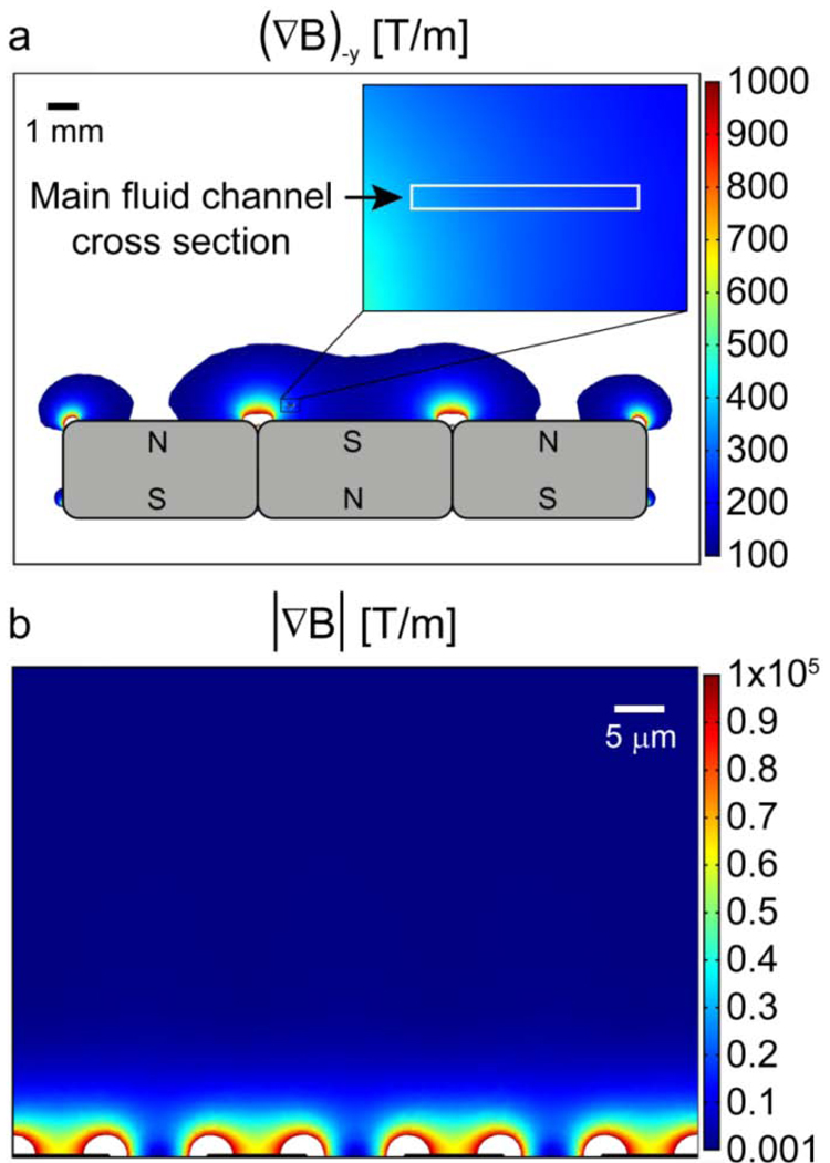
In conventional, large-scale magnetic systems, precision control of magnetic field gradients often requires accurate machining of pole pieces and mechanical alignment8. In contrast, microfabrication technology enables simpler approaches for generating large magnetic field gradients reproducibly, automatically and inexpensively. For example, recent work by Adams et al.35 demonstrated accurate control over magnetic field gradients within a microfluidic channel over two length scales. Long-range gradients were controlled with a series of external rare-earth (neodymium iron boron) permanent magnets in an alternating configuration (Fig 1A). These magnets generate ~ 0.5 T at their surface and, a gradient of ~200 T/m in the negative y-direction can be generated over the entire cross-sectional area of the microfluidic channel in this configuration. On the other hand, short-range gradients were generated by microfabricated ferromagnetic structures (nickel) within the microchannel, as initially described by Inglis and coworkers20 (Fig 1B). Here, due to the large difference in relative magnetic permeability between the nickel structures and the biological sample (μr,nickel = 200, μr,sample ~ 1), the external field reproducibly and accurately induces extremely large short-range gradients (~ 104 T/m) within ~ 8 μm of the pattern.
Figure 1.
Numerical simulation of long-range and short-range magnetic field gradients in a microfluidic device designed for magnetophoretic separation. a) Long-range gradients are produced by a series of external permanent magnets, with the magnitude of the -y direction gradient exceeding 200 T/m over the cross-section of a microfluidic channel located 0.5 mm above the surface of the magnets. b) An abrupt change in relative permittivity (μr) between microfabricated nickel features (μr ~200) and the biological sample (μr ~1) creates an extremely large short-range magnetic field gradient. The magnitude of this gradient is > 104 T/m within 8 μm of the microfabricated features. Image adapted from Adams et al.35 with permission. ©PNAS 2008.
Magnetic trapping enables stringent washing and high purity separation
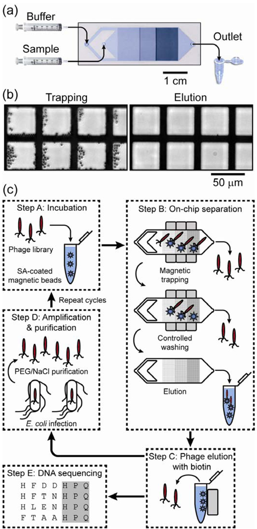
The capability to reproducibly generate large magnetophoretic forces can be combined with stringent, continuous washing within the microchannel to achieve very high purities. To illustrate this point, Liu et al.36 described the Micro-Magnetic Separation (MMS) device for highly efficient screening of phage libraries (Fig. 2A). In this application, a large, diverse library of phage particles displaying unique peptide sequences is screened to specifically isolate clones that bind tightly to a target protein. For assays such as this, high purity separation is essential37, 38.
Figure 2.
Overview of the Micro-Magnetic Separation (MMS) device and its application for high-purity phage library screening. a) Micrograph of the MMS device showing the channel design, nickel pattern and flow path. The device dimensions are 64 mm ×15.7 mm × 1.5 mm (L × W × H), and the height and width of the microfluidic channel are 30 μm and 12 mm, respectively. b) Bright field optical micrographs of the nickel pattern in the microchannel. When an external field is applied (left), the large magnetic field gradients at the edges of the nickel pattern effectively trap the beads, but when the external field is removed (right), the nickel pattern is de-magnetized and the beads are efficiently eluted. c) Selection of the phage display library using the MMS device. Step A: The phage library is mixed and incubated with target molecule-conjugated magnetic beads. Step B: NeFeB permanent magnets are applied to the MMS device to specifically trap phage particles bound to the magnetic beads, which are subsequently held in place and washed under controlled conditions to eliminate nonspecific interactions. The nickel patterns are then de-magnetized, and the phage-carrying beads are eluted. Step C: The phage are dissociated from the protein-conjugated beads by competitive elution with biotin. Step D: Isolated phage are amplified via infection of E. coli cells, and subsequently purified with PEG/NaCl solution for additional rounds of selection or analysis. Step E: Clones from each round of selection are randomly picked and their DNA is sequenced. Figure reprinted from Liu et al.36 with permission of the authors.
In the MMS device, target protein-conjugated magnetic beads are trapped by a series of microfabricated ferromagnetic structures embedded within the channel. As described above, the difference in magnetic permeabilities between the sample and the ferromagnetic structures creates high spatial variation in the magnetic field, resulting in a magnetophoretic force of tens of nanonewtons at the edges of the ferromagnetic structures where the gradient is the largest (Fig. 2B, left). Importantly, this trapping is reversible; upon removal of the external field, the ferromagnetic structures demagnetize and the trapped particles are efficiently eluted (Fig 2B, right). Under experimental conditions, the authors found that 99.5% of the beads that entered the device were successfully trapped, allowing for the use of a small number of beads without significant loss.
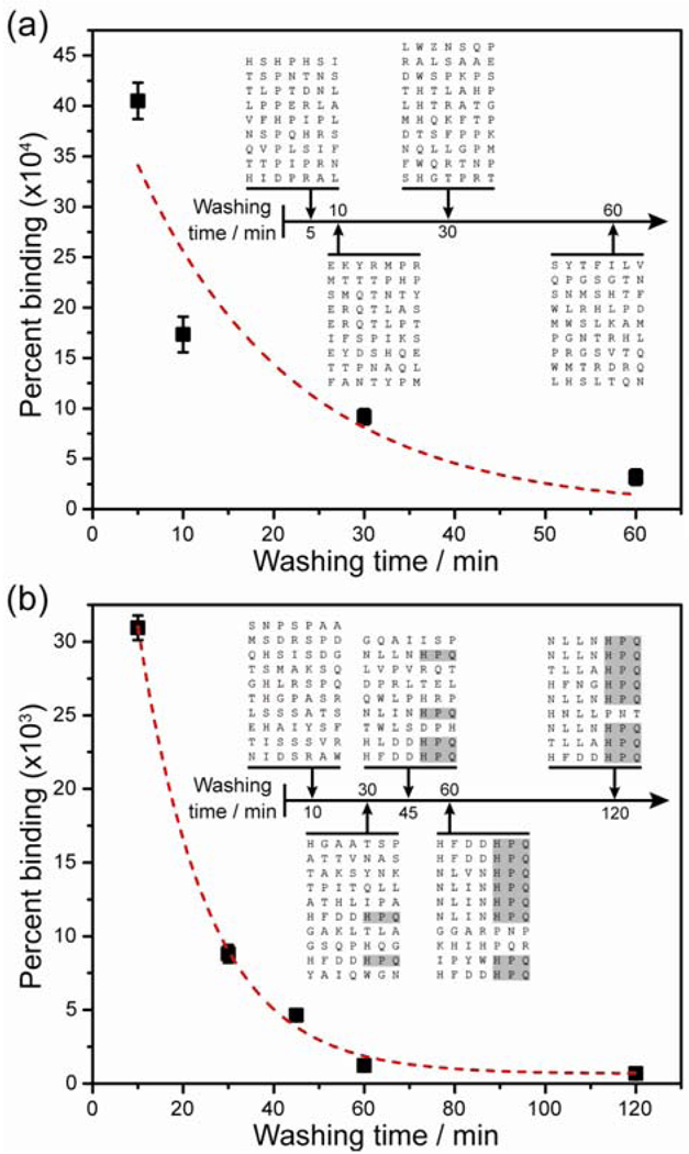
The MMS device enables precise control over washing stringency during the phage selection process, as illustrated in figure 2C. The effects of washing time on the pool of selected peptide sequences were analyzed after two rounds of selection, with the washing flow rate within the chip fixed at 10 ml/hr. At this flow rate, the maximum Stokes drag force experienced by the beads was ~10 pN, which was significantly lower than the magnetic trapping force (~ 10 nN) and ensured that targets were not eluted inadvertently. The authors observed a non-linear, inversely proportional relationship between the percentage of bound phage and the washing time, as weakly- or non-binding phages were progressively removed by longer wash times (Fig 3A, B). Phage removal over time was modeled as a first order process, which can be described by simple exponential decay
| (5) |
TnQTable5where S is the density function at time t for the phage subpopulation remaining bound to the target, S0 is the amplitude constant and kd is the dissociation rate constant.
Figure 3.
The importance of controlling the washing conditions during phage selection. a) In the first round of selection, the percentage of recovered phage as a function of washing time decays non-linearly, as non-specifically bound and weak binding phage are removed. When modeled as a first order exponential (dashed line), the dissociation rate constant was kd1 = 1.0±0.1∙10−3 s−1. (Inset) The canonical target-binding peptide motif (HPQ) was not found in clones isolated after the first round. b) In the second round, the percentage of bound phage also showed an exponential decay as stringency (washing time) increased, with a remarkably similar dissociation rate constant of kd2 = 1.07±0.04∙10−3 s−1. (Inset) The percentage of clones with the HPQ motif increased monotonically as a function of washing time; after 120 minutes of washing, 8 out of 9 clones contained this motif. Figure reprinted from Liu et al.36 with permission of the authors.
In this platform, independent and precise control over magnetic trapping forces and washing stringency during phage selection had a direct impact on the effectiveness of the peptide screening process—as washing duration increased, the probability of obtaining consensus peptide sequences increased monotonically (Fig 3B). After 120 min of washing in the second round, 8 of 9 randomly sequenced clones exhibited the consensus binding sequence histidine-proline-glutamine (HPQ), compared with only 2 of 10 clones after 30 min of washing. This is one example of how microfluidics technology can enable extremely high purity separation in a small sample volume.
Accurate control of forces permits multi-target separation
In conventional magnetic selection approaches (e.g., tubes and columns), only binary selection is possible because the mechanism of separation is based a single parameter—the presence or absence of magnetization—and isolation of multiple targets requires multiple stages of purification. However, this is not a fundamental limitation of magnetic separation, and more sophisticated multi-target separation is possible through precise control of magnetic forces. The ability to simultaneously separate multiple target cells via magnetophoresis could reduce both labor time and associated cost per assay compared with conventional magnetic separation, and enable the development of novel purification strategies such as separation of target cells based on the degree of surface marker expression39, 40 or magnetic particle uptake41.
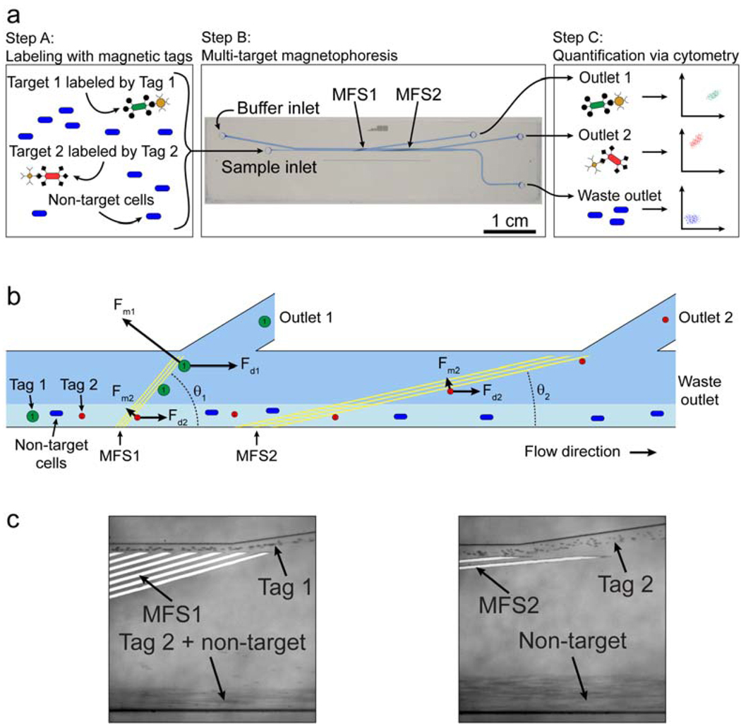
Multi-target magnetic separation has been previously described at the macro-scale8; however, the generation of large magnetic field gradients in this context is cumbersome, requiring precise positioning of magnets. The generation of such field gradients is greatly simplified in microfluidic systems, however, and we have recently exploited the benefits of working at this scale in the development of their Multi-Target Magnetic Activated Cell Sorter (MT-MACS) chip (Fig 4)35. The MT-MACS device incorporates multi-stream laminar flow architecture and micro-scale magnetic field control for continuous sorting of multiple target cells into independent outlets with high purity and throughput. Here, labeling is performed with two types of affinity reagent-coupled superparamagnetic tags, each with distinct properties of magnetization (M) and radius (r), which specifically bind surface markers expressed by different target cells (Fig 4A). The labeled sample mixture and running buffer enter the device through separate inlets; within the device, the balance of the fluidic (Fd) and magnetophoretic (Fm) forces has a non-linear dependence on the radius, and MT-MACS uses this as a basis to deflect the two types of target cells into two spatially segregated, independent outlets. Briefly, as the cells travel through the device, they encounter two consecutive sets of microfabricated ferromagnetic strips (MFS), each arranged at different angles (Fig 4B). Labeled cells are deflected along the MFS if the magnetic force retaining the particle near the MFS edge is greater than the component of the fluidic drag force pulling the labeled cell away from the MFS (i.e., Fm > Fd sin(θ)). At MFS 1 (θ1 =15°), cells labeled with tag 1 (larger in M and r) are deflected because Fm > Fd sin(θ1), whereas cells labeled with tag 2 (smaller in M and r) do not meet this condition and are not deflected. These are instead deflected at MFS 2 (θ2 =5°), where Fm > Fdsin(θ2). Unlabeled, non-target cells are not deflected by either MFS array, and elute through the waste outlet.
Figure 4.
MT-MACS separation architecture. a) The separation process. Step A: The sample contains an excess of non-target cells and two different target cell types, which are labeled with two different magnetic tags via specific surface markers. Step B: The sample is continuously pumped into the device, where the two target cell types are sorted into spatially segregated, independent outlets at regions of high magnetic field gradient generated by two sets of microfabricated ferromagnetic strips (MFS1 and MFS2). Step C: The eluted fractions from each outlet are analyzed via flow cytometry. b) A free-body diagram showing the balance of forces at the MFS structures. At MFS 1 (θ1 =15°), tag 1-labeled cells are deflected and elute through outlet 1 because Fm1>Fd1sin(θ1) . This is not the case for tag 2-labeled target 2 cells, which are instead deflected at MFS 2 (θ2 =5°), where Fm2 >Fd2 sin(θ2) and elute through outlet 2. Non-target cells are not deflected by either MFS and elute through the waste outlet. c) Optical micrographs (100X magnification) of tags being separated at the two MFS structures at a total flow rate of 47 ml/hr (sample = 5 ml/hr, buffer = 42 ml/hr). Tag 1 is deflected at MFS 1 (left), while tag 2 is deflected by MFS2 (right). Figure taken from Adams et al.35 with permission of the authors. © PNAS 2008
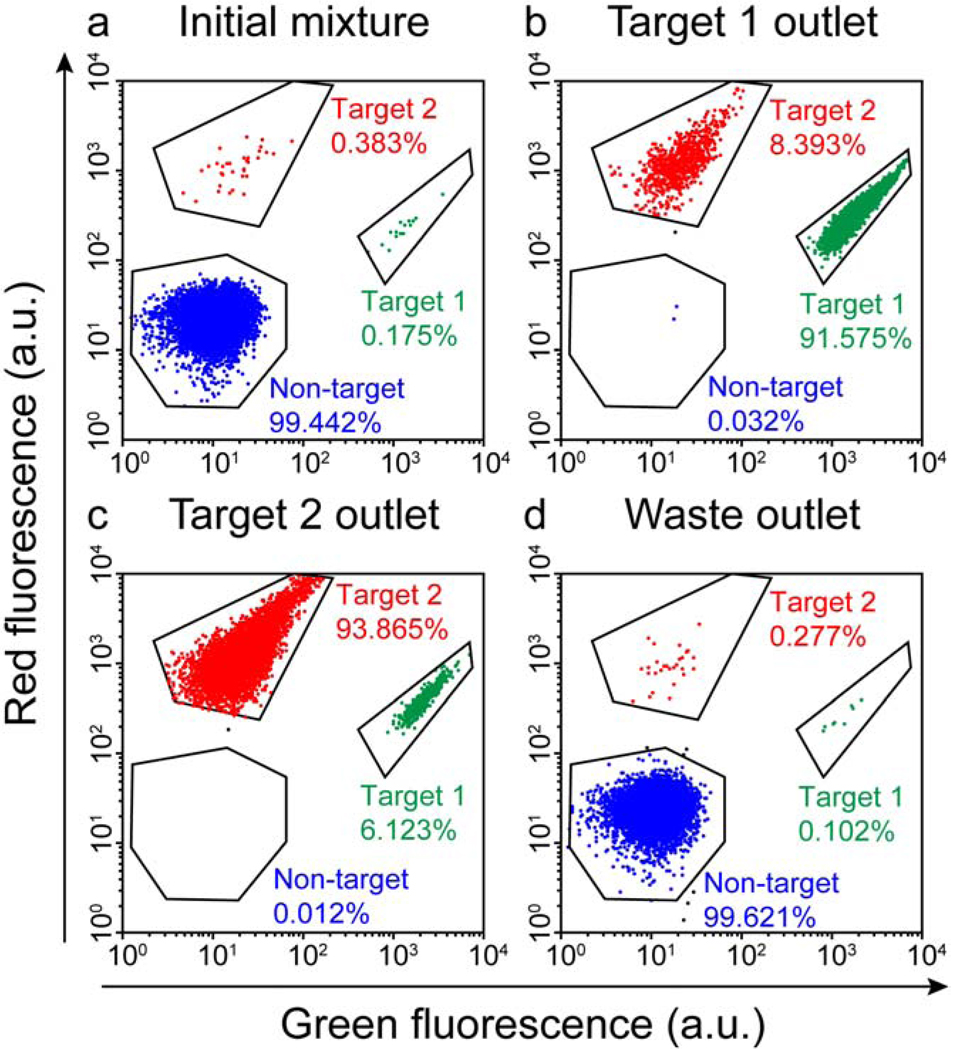
The MT-MACS device achieves remarkable enrichment of multiple target cells; working with a mixture of tagged bacterial cells, even low concentrations of labeled target cells (< 0.4%) can be simultaneously enriched into highly purified fractions for each target cell type (> 90%) in a single pass through the device at a throughput of ~109 cells/h (Fig 5). This capability to simultaneously separate multiple targets with high purity and throughput could reduce dependence on costly and complex separation procedures such as FACS. However, the MT-MACS chip is still not capable of true multi-parameter separation (i.e., separation based on the presence of two surface markers), and we will review our recent progress towards addressing this technological challenge in the next section.
Figure 5.
Cytometric analysis of simultaneous,high-purity enrichment of multiple bacterial target cell types in the MT-MACS device. a) The initial sample mixture consists of 99.442% non-target cells (expressing BFP) doped with 0.175% target 1 cells and 0.383% target 2 cells. b) The cell mixture recovered at the target 1 outlet consisted of 91.575% target 1 cells, 8.393% target 2 cells, and 0.032% non-target cells. c) The output at the target 2 outlet was comprised of 93.865% target 2 cells, 6.123% target 1 cells, and 0.012% non-target cells. d) Waste outlet output consisted of 99.621% non-target cells, 0.102% target 1 cells and 0.277% target 2 cells. Figure taken from Adams et al.35 with permission of the authors. © PNAS 2008
Integration of multiple separation forces
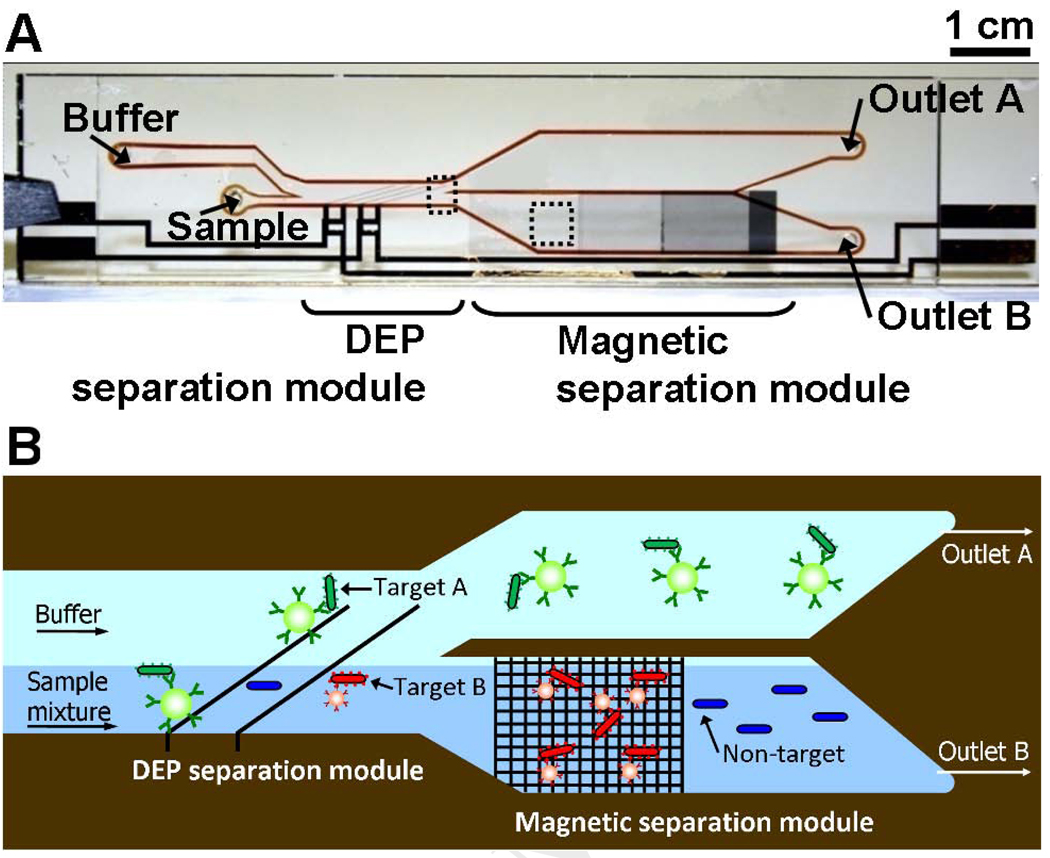
As a first step towards the goal of integrated multi-parameter selection, Kim et al.42 combined multiple separation mechanisms within a monolithic microfluidic device. The integrated Dielectrophoretic-Magnetic Activated Cell Sorter (iDMACS) is a two-input, multiple-output device wherein two types of target cells, labeled with either dielectrophoretic tags (polystyrene microparticles) or magnetic tags (iron oxide-based nanoparticles), are sorted in the presence of an excess background of non-target cells using two independent force fields (Fig 6A).
Figure 6.
Multi-target bacterial cell sorting via iDMACS. a) Photograph of the fabricated idMACS device. Overall device size is 7 cm × 1.5 cm, including both DEP and magnetic separation modules. b) The physics of multi-target separation via iDMACS. Target A cells, labeled with DEP tags, are deflected at a set of angled electrodes to elute through outlet A. Subsequently, an array of ferromagnetic strips captures magnetically-tagged target B cells, which are then eluted through outlet B after washing. Unlabeled non-target cells are neither deflected by the electrodes nor captured by the strips. Figure reprinted from Kim et al.42 with permission of the authors.
iDMACS separation is performed in two stages. First, cells are subjected to dielectrophoretic forces (FDEP) created by a non-uniform electric field generated by a set of titanium/gold electrodes (Fig. 6B). In this electrode configuration, the FDEP can be described by
| (6) |
TnQTable6where εm is the permittivity of the medium, r is the distance from the electrode, a is the particle radius and U is the applied RMS voltage 18. fcm(ω) is the Clausius-Mosotti factor that describes the competitive polarization between the particle and the suspension medium, given by
| (7) |
where εp is the permittivity of the particle and ω is the applied frequency. iDMACS operates in a low-conductivity buffer (0.1 × PBS, 1 % BSA, 20 % glycerol), which sets fcm(ω) negative; therefore, the overall force is negative and objects are repelled from the electrodes. Here, if the sorting criterion FDEP > Fd sinθ is satisfied43–45, the particle is deflected along the electrodes, re-directed into a new flowstream, and eluted through outlet A. Only DEP tag-labeled cells are deflected by the angled electrodes, because they experience FDEP (~ 2 nN) that exceeds FHD (~0.4 nN) in the direction perpendicular to the electrodes. On the other hand, magnetically-labeled or unlabeled cells do not meet the DEP sorting criterion, and continue undeflected along the microchannel.
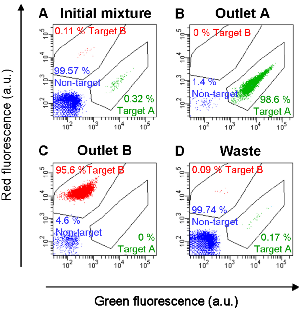
The second stage of interrogation occurs at an array of microfabricated nickel strips (Fig. 6B) that generate high magnetic field gradients as described above. Under standard operating conditions, the magnetic force on labeled cells is estimated to be ~0.3 nN, significantly greater than the fluidic drag force (~0.07 nN), such that magnetically labeled cells are effectively trapped at the nickel strips. As the magnetic separation component is robust to a wide range of environmental conditions, the same low-conductivity buffer is used throughout the device. Following washing, the external magnets are removed and target cells are eluted. A single pass through the iDMACS device yielded up to ~3,000-fold enrichment of tags and ~900-fold enrichment of bacterial cells at a throughput of ~2.5 × 10⁷ cells/h (Fig 7). Notably, because of the use of two distinct separation forces, there is no crossover contamination between the two target types (i.e., no target A cells in outlet B, and no target B cells in outlet A) in the two enriched populations. Though not shown here, it is certainly possible to combine other separation forces that do not interact with each other (e.g. acoustic, optical, etc.) and such approaches may yield a viable path towards multi-parameter selection.
Figure 7.
Multi-target bacterial cell sorting performance using the iDMACS device. a) Two-color flow cytometry measurement of the initial sample, which consisted of an excess of non-target cells (99.57%) with low concentrations of labeled target A (0.32%) and target B (0.11% ) cells. b) After a single round of separation, the outlet A fraction contained almost exclusively target A cells (98.6%, a 310-fold enrichment), and no target B cells (0%). c) Conversely, the outlet B fraction contained primarily target B cells (95.6%, a 870-fold enrichment) and no target A cells (0%). d) The fraction collected at the waste outlet consisted of small quantities of target A (0.17%) and target B (0.09%) cells and mostly non-target cells (99.74%). Figure reprinted from Kim et al.42 with permission of the authors.
Conclusion
In this report, we have highlighted a number of platforms for particle and cell separation that exploit the distinctive features and advantages of microfluidics technology. Using high-gradient magnetophoresis as an example, we have shown that the accurate and reproducible methods of reversibly trapping particles and controlling washing conditions that can be achieved within microchannels enable high purity separation. We have also shown that the capability to accurately control both fluidic and magnetic forces enables novel sorting functions such as simultaneous multi-target selection. Finally, we have noted the benefits of integrating multiple actuation forces into a monolithic device to enable new separation functionalities that would be difficult to implement in conventional macroscale systems. Besides the iDMACS device described here, there are several other examples of platforms that successfully combine forces for multi-target separation. For example, Wiklund et al. effectively combined dielectrophoresis and acoustophoresis46, while Liu et al. demonstrated dielectrophoresis with travelling magnetic fields47. In principle, such devices may be operated in parallel to increase throughput48, 49, or in series to improve purity50.
We believe that an important future challenge may lie in the integration of such “front-end” sample preparation techniques with “back-end” analytical methods, and we are beginning to see such integrated systems. For example, Liu et al. have demonstrated a self-contained chip that integrates magnetic capture, PCR amplification and DNA microarray detection of bacteria51, and more recently, Nagrath et al. combined antibody capture of rare circulating tumor cells in a micropillar array with subsequent on-chip fluorescent detection52. We anticipate that the advent of such highly integrated “sample in-result out” systems53 that can process crude biological samples and yield quantitative, molecular diagnostic information in a disposable format will have a significant impact on many areas of analytical biotechnology, and may hold the key for personalized medicine and point-of-care diagnostics.
Acknowledgments
We thank the ONR, NIH, ARO Institute for Collaborative Biotechnologies (ICB), and Armed Forces Institute for Regenerative Medicine (AFIRM) for their financial support. We thank Unyoung Kim and Yanli Liu for helpful discussions.
Biography

Footnotes
Publisher's Disclaimer: This is a PDF file of an unedited manuscript that has been accepted for publication. As a service to our customers we are providing this early version of the manuscript. The manuscript will undergo copyediting, typesetting, and review of the resulting proof before it is published in its final citable form. Please note that during the production process errors may be discovered which could affect the content, and all legal disclaimers that apply to the journal pertain.
References
- 1.West J, Becker M, Tombrink S, Manz A. Micro total analysis systems: latest aachievements. Anal. Chem. 2008;80(12):4403–4419. doi: 10.1021/ac800680j. [DOI] [PubMed] [Google Scholar]
- 2.Lee HJ, Goodrich TT, Corn RM. SPR imaging measurements of 1-D and 2-D DNA microarrays created from microfluidic channels on gold thin films. Anal. Chem. 2001;73(22):5525–5531. doi: 10.1021/ac010762s. [DOI] [PubMed] [Google Scholar]
- 3.Margu1ies M, Egholm M, Altman WE, Attiya S, Bader JS, Bemben LA, Berka J, Braverman MS, Chen YJ, Chen ZT, Dewell SB, Du L, Fierro JM, Gomes KV, Godwin BC, He W, Helgesen S, Ho CH, Irzyk GP, Jando SC, Alenquer MLI, Jarvie TP, Jirage KB, Kim JB, Knight JR, Lanza JR, Leamon JH, Lefkowitz SM, Lei M, Li J, Lohman KL, Lu H, Makhijani VB, McDade KE, McKenna MP, Myers EW, Nickerson E, Nobile JR, Plant R, Puc BP, Ronan MT, Roth GT, Sarkis GJ, Simons JF, Simpson JW, Srinivasan M, Tartaro KR, Tomasz A, Vogt KA, Volkmer GA, Wang SH, Wang Y, Weiner MP, Yu PG, Begley RF, Rothberg JM. Genome sequencing in microfabricated high-density picolitre reactors. Nature. 2005;437(7057):376–380. doi: 10.1038/nature03959. [DOI] [PMC free article] [PubMed] [Google Scholar]
- 4.Yager P, Edwards T, Fu E, Helton K, Nelson K, Tam MR, Weigl BH. Microfluidic diagnostic technologies for global public health. Nature. 2006;442(7101):412–418. doi: 10.1038/nature05064. [DOI] [PubMed] [Google Scholar]
- 5.Hansel TT, Devries IJM, Iff T, Rihs S, Wandzilak M, Betz S, Blaser K, Walker C. An Improved Immunomagnetic Procedure for the isolation of highly purified human blood eosinophils. J. Immunol. Meth. 1991;145(1–2):105–110. doi: 10.1016/0022-1759(91)90315-7. [DOI] [PubMed] [Google Scholar]
- 6.Miltenyi S, Muller W, Weichel W, Radbruch A. High-gradient magnetic cell-separation with MACS. Cytometry. 1990;11(2):231–238. doi: 10.1002/cyto.990110203. [DOI] [PubMed] [Google Scholar]
- 7.Safarik I, Safarikova M. Use of magnetic techniques for the isolation of cells. J. Chromatogr. B. 1999;722(1–2):33–53. [PubMed] [Google Scholar]
- 8.Chalmers JJ, Zborowski M, Sun LP, Moore L. Flow through, immunomagnetic cell separation. Biotechnol. Progr. 1998;14(1):141–148. doi: 10.1021/bp970140l. [DOI] [PubMed] [Google Scholar]
- 9.Ashcroft RG, Lopez PA. Commercial high speed machines open new opportunities in high throughput flow cytometry (HTFC) J. Immunol. Meth. 2000;243(1–2):13–24. doi: 10.1016/s0022-1759(00)00219-2. [DOI] [PubMed] [Google Scholar]
- 10.Ibrahim SF, van den Engh G. High-speed cell sorting: fundamentals and recent advances. Curr. Opin. Biotech. 2003;14(1):5–12. doi: 10.1016/s0958-1669(02)00009-5. [DOI] [PubMed] [Google Scholar]
- 11.Shizuru JA, Negrin RS, Weissman IL. Hematopoietic stem and progenitor cells: Clinical and preclinical regeneration of the hematolymphoid system. Annu. Rev. Med. 2005;56:509–538. doi: 10.1146/annurev.med.54.101601.152334. [DOI] [PubMed] [Google Scholar]
- 12.Pantel K, Brakenhoff RH, Brandt B. Detection, clinical relevance and specific biological properties of disseminating tumour cells. Nat Rev. Cancer. 2008;8(5):329–340. doi: 10.1038/nrc2375. [DOI] [PubMed] [Google Scholar]
- 13.Leith D. Drag on nonspherical objects. Aerosol Sci. Tech. 1987;6(2):153–161. [Google Scholar]
- 14.Huang LR, Cox EC, Austin RH, Sturm JC. Continuous particle separation through deterministic lateral displacement. Science. 2004;304(5673):987–990. doi: 10.1126/science.1094567. [DOI] [PubMed] [Google Scholar]
- 15.Yamada M, Nakashima M, Seki M. Pinched flow fractionation: Continuous size separation of particles utilizing a laminar flow profile in a pinched microchannel. Anal Chem. 2004;76(18):5465–5471. doi: 10.1021/ac049863r. [DOI] [PubMed] [Google Scholar]
- 16.Choi S, Song S, Choi C, Park J-K. Continuous blood cell separation by hydrophoretic filtration. Lab Chip. 2007;7(11):1532–1538. doi: 10.1039/b705203k. [DOI] [PubMed] [Google Scholar]
- 17.Gascoyne PRC, Vykoukal J. Particle separation by dielectrophoresis. Electrophoresis. 2002;23(13):1973–1983. doi: 10.1002/1522-2683(200207)23:13<1973::AID-ELPS1973>3.0.CO;2-1. [DOI] [PMC free article] [PubMed] [Google Scholar]
- 18.Durr M, Kentsch J, Muller T, Schnelle T, Stelzle M. Microdevices for manipulation and accumulation of micro- and nanoparticles by dielectrophoresis. Electrophoresis. 2003;24(4):722–731. doi: 10.1002/elps.200390087. [DOI] [PubMed] [Google Scholar]
- 19.Voldman J. Electrical forces for microscale cell manipulation. Annu. Rev. Biomed. Eng. 2006;8(1):425–454. doi: 10.1146/annurev.bioeng.8.061505.095739. [DOI] [PubMed] [Google Scholar]
- 20.Inglis DW, Riehn R, Austin RH, Sturm JC. Continuous microfluidic immunomagnetic cell separation. Appl. Phys. Lett. 2004;85(21):5093–5095. [Google Scholar]
- 21.Pamme N, Manz A. On-chip free-flow magnetophoresis: continuous flow separation of magnetic particles and agglomerates. Anal Chem. 2004;76(24):7250–7256. doi: 10.1021/ac049183o. [DOI] [PubMed] [Google Scholar]
- 22.Pamme N. Magnetism and microfluidics. Lab Chip. 2006;6(1):24–38. doi: 10.1039/b513005k. [DOI] [PubMed] [Google Scholar]
- 23.Yellen BB, Erb RM, Son HS, Hewlin R, Jr, Shang H, Lee GU. Traveling wave magnetophoresis for high resolution chip based separations. Lab Chip. 2007;7(12):1681–1688. doi: 10.1039/b713547e. [DOI] [PubMed] [Google Scholar]
- 24.Mac Donald MP, Spalding GC, Dholakia K. Microfluidic sorting in an optical lattice. Nature. 2003;426(6965):421–424. doi: 10.1038/nature02144. [DOI] [PubMed] [Google Scholar]
- 25.MacDonald MD, Neale S, Paterson L, Richies A, Dholakia K, Spalding GC. Cell cytometry with a light touch: Sorting microscopic matter with an optical lattice. J Biol. Regul. Homeost Agents. 2004;18(2):200–205. [PubMed] [Google Scholar]
- 26.Chiou PY, Ohta AT, Wu MC. Massively parallel manipulation of single cells and microparticles using optical images. Nature. 2005;436(7049):370–372. doi: 10.1038/nature03831. [DOI] [PubMed] [Google Scholar]
- 27.Petersson F, Aberg L, Sward-Nilsson A-M, Laurell T. Free flow acoustophoresis: microfluidic-based mode of particle and cell separation. Anal. Chem. 2007;79(14):5117–5123. doi: 10.1021/ac070444e. [DOI] [PubMed] [Google Scholar]
- 28.Nilsson A, Petersson F, Jonsson H, Laurell T. Acoustic control of suspended particles in micro fluidic chips. Lab Chip. 2004;4(2):131–135. doi: 10.1039/b313493h. [DOI] [PubMed] [Google Scholar]
- 29.Petersson F, Nilsson A, Holm C, Jonsson H, Laurell T. Separation of lipids from blood utilizing ultrasonic standing waves in microfluidic channels. Analyst. 2004;129(10):938–943. doi: 10.1039/b409139f. [DOI] [PubMed] [Google Scholar]
- 30.Hawkes JJ, Barber RW, Emerson DR, Coakley WT. Continuous cell washing and mixing driven by an ultrasound standing wave within a microfluidic channel. Lab Chip. 2004;4(5):446–452. doi: 10.1039/b408045a. [DOI] [PubMed] [Google Scholar]
- 31.Gijs MAM. Magnetic bead handling on-chip: new opportunities for analytical applications. Microfluid. Nanofluid. 2004;1(1):22–40. [Google Scholar]
- 32.Schenck JF. Physical interactions of static magnetic fields with living tissues. Prog. Biophys. Mol Bio. 2005;87(2–3):185–204. doi: 10.1016/j.pbiomolbio.2004.08.009. [DOI] [PubMed] [Google Scholar]
- 33.Riviere C, Boudghene FP, Gazeau F, Roger J, Pons JN, Laissy JP, Allaire E, Michel JB, Letourneur D, Deux JF. Iron oxide nanoparticle-labeled rat smooth muscle cells: Cardiac MR imaging for cell graft monitoring and quantitation. Radiology. 2005;235(3):959–967. doi: 10.1148/radiol.2353032057. [DOI] [PubMed] [Google Scholar]
- 34.Perea H, Aigner J, Hopfner U, Wintermantel E. Direct magnetic tubular cell seeding: A novel approach for vascular tissue engineering. Cells Tissues Organs. 2006;183(3):156–165. doi: 10.1159/000095989. [DOI] [PubMed] [Google Scholar]
- 35.Adams JD, Kim U, Soh HT. Multitarget magnetic activated cell sorter. P. Natl. Acad. Sci. USA. 2008;105(47):18165–18170. doi: 10.1073/pnas.0809795105. [DOI] [PMC free article] [PubMed] [Google Scholar]
- 36.Liu Y, Adams JD, Turner K, Cochran FV, Gambhir SS, Soh HT. Controlling the selection stringency of phage display using a microfluidic device. Lab Chip. 2009;9(8):1033–1036. doi: 10.1039/b820985e. [DOI] [PubMed] [Google Scholar]
- 37.Lu D, Shen JQ, Vil MD, Zhang HF, Jimenez X, Bohlen P, Witte L, Zhu ZP. Tailoring in vitro selection for a picomolar affinity human antibody directed against vascular endothelial growth factor receptor 2 for enhanced neutralizing activity. J. Biol. Chem. 2003;278(44):43496–43507. doi: 10.1074/jbc.M307742200. [DOI] [PubMed] [Google Scholar]
- 38.Zhuang GQ, Katakura Y, Furuta T, Omasa T, Kishimoto M, Suga K. A kinetic model for a biopanning process considering antigen desorption and effective antigen concentration on a solid phase. J. Biosci. Bioeng. 2001;91(5):474–481. doi: 10.1263/jbb.91.474. [DOI] [PubMed] [Google Scholar]
- 39.McCloskey KE, Moore LR, Hoyos M, Rodriguez A, Chalmers JJ, Zborowski M. Magnetophoretic cell sorting is a function of antibody binding capacity. Biotechnol. Progr. 2003;19(3):899–907. doi: 10.1021/bp020285e. [DOI] [PubMed] [Google Scholar]
- 40.Schneider T, Moore LR, Jing Y, Haam S, Williams PS, Fleischman AJ, Roy S, Chalmers JJ, Zborowski M. Continuous flow magnetic cell fractionation based on antigen expression level. J. Biochem. Bioph. Meth. 2006;68(1):1–21. doi: 10.1016/j.jbbm.2006.02.011. [DOI] [PubMed] [Google Scholar]
- 41.Pamme N, Wilhelm C. Continuous sorting of magnetic cells via on-chip free-flow magnetophoresis. Lab Chip. 2006;6(8):974–980. doi: 10.1039/b604542a. [DOI] [PubMed] [Google Scholar]
- 42.Kim U, Soh HT. Simultaneous sorting of multiple bacterial targets using an integrated dielectrophoretic-magnetic activated cell sorter. Lab Chip. 2009 doi: 10.1039/b903950c. In press. [DOI] [PubMed] [Google Scholar]
- 43.Hu KY, Bessette PH, Qian JR, Meinhart CD, Daugherty PS, Soh HT. Marker-specific sorting of rare cells using dielectrophoresis. Proc. Natl. Acad. Sci. USA. 2005;102(44):15757–15761. doi: 10.1073/pnas.0507719102. [DOI] [PMC free article] [PubMed] [Google Scholar]
- 44.Kim U, Qian J, Kenrick SA, Daugherty PS, Soh HT. Multitarget dielectrophoresis activated cell sorter. Anal. Chem. 2008;80(22):8656–8661. doi: 10.1021/ac8015938. [DOI] [PMC free article] [PubMed] [Google Scholar]
- 45.Kim U, Shu CW, Dane KY, Daugherty PS, Wang JYJ, Soh HT. Selection of mammalian cells based on their cell-cycle phase using dielectrophoresis. Proc Natl. Acad. Sci. USA. 2007;104(52):20708–20712. doi: 10.1073/pnas.0708760104. [DOI] [PMC free article] [PubMed] [Google Scholar]
- 46.Wiklund M, Gunther C, Lemor R, Jager M, Fuhr G, Hertz HM. Ultrasonic standing wave manipulation technology integrated into a dielectrophoretic chip. Lab Chip. 2006;6(12):1537–1544. doi: 10.1039/b612064b. [DOI] [PubMed] [Google Scholar]
- 47.Liu CK, Lagae L, Borghs G. Manipulation of magnetic particles on chip by magnetophoretic actuation and dielectrophoretic levitation. Appl Phys. Lett. 2007;90(18):184109. [Google Scholar]
- 48.Laurell T, Petersson F, Nilsson A. Chip integrated strategies for acoustic separation and manipulation of cells and particles. Chem. Soc Rev. 2007;36(3):492–506. doi: 10.1039/b601326k. [DOI] [PubMed] [Google Scholar]
- 49.Tan HD, Yeung ES. Automation and integration of multiplexed on-line sample preparation with capillary electrophoresis for high-throughput DNA sequencing. Anal. Chem. 1998;70(19):4044–4053. doi: 10.1021/ac980406i. [DOI] [PubMed] [Google Scholar]
- 50.Bessette PH, Hu K, Soh HT, Daugherty PS. Microfluidic library screening for mapping antibody epitopes. Anal Chem. 2007;79(5):2174–2178. doi: 10.1021/ac0616916. [DOI] [PubMed] [Google Scholar]
- 51.Liu RH, Yang JN, Lenigk R, Bonanno J, Grodzinski P. Self-contained, fully integrated biochip for sample preparation, polymerase chain reaction amplification, and DNA microarray detection. Anal. Chem. 2004;76(7):1824–1831. doi: 10.1021/ac0353029. [DOI] [PubMed] [Google Scholar]
- 52.Nagrath S, Sequist LV, Maheswaran S, Bell DW, Irimia D, Ulkus L, Smith MR, Kwak EL, Digumarthy S, Muzikansky A, Ryan P, Balis UJ, Tompkins RG, Haber DA, Toner M. Isolation of rare circulating tumour cells in cancer patients by microchip technology. Nature. 2007;450(7173):1235–1239. doi: 10.1038/nature06385. [DOI] [PMC free article] [PubMed] [Google Scholar]
- 53.Easley CJ, Karlinsey JM, Bienvenue JM, Legendre LA, Roper MG, Feldman SH, Hughes MA, Hewlett EL, Merkel TJ, Ferrance JP, Landers JP. A fully integrated microfluidic genetic analysis system with sample-in-answer-out capability. Proc Natl Acad. Sci. USA. 2006;103(51):19272–19277. doi: 10.1073/pnas.0604663103. [DOI] [PMC free article] [PubMed] [Google Scholar]


