

Abstract
The paper describes a protocol to fabricate cell-laden microgel assemblies with pre-defined micro-architecture and complexity by a bottom-up approach, which can be used for tissue engineering applications. The assembly process was driven by the hydrophobic effect in the water/oil interface. By agitating hydrophilic microgels in hydrophobic medium, the shape-controlled microgel units assemble in an organized manner to locally minimize the interaction free energy (the surface area exposed to the oil). The assembly process was shown to be controlled by several parameters, such as external energy input, surface tension, and microgel dimensions. This assembly approach was used to build multi-component cell-laden constructs by assembling microgel building blocks and performing a secondary cross-linking reaction. This bottom-up approach for the directed assembly of cell-laden microgels offers a scalable method to fabricate 3D tissue constructs with biomimetic structure.
Keywords: Bottom-up, Tissue engineering, Assembly, Hydrogel
Introduction
This paper describes in detail the procedure for a bottom-up approach to assemble cell-laden microscale hydrogels (microgels) for fabrication of 3D tissue constructs.3 Bottom-up approaches build larger tissue constructs by the assembly of smaller cell-laden building blocks (i.e. microgels), which mimic the living tissue architecture from repeating functional units (i.e. islet, nephron or lobule).2,4 Thus far, bottom-up assembly of cell-laden microgels has been gaining increasing attention in the tissue engineering research, with numerous approaches developed including random assembly,6 manual manipulation,8 multi-layer photo-patterning,5,7 and microfluidic-directed assembly.1 Random assembly of microgel modules has the advantage of being rapid and simple, but lacks control over the final structure of the microgel assembly; manual manipulations are relatively slow processes and not scalable; multi-layer photo-patterning and microfluidic-directed assembly are able to create highly sophisticated microgel assembly architectures, but requires longer operational time and sophisticated equipments.
The bottom-up assembly process presented here aims to direct the assembly of cell-laden microgels in a simple and highly scalable manner. The assembly process is driven by the ‘hydrophobic effect’—the thermodynamic tendency of multiphase liquid–liquid systems to minimize the surface free energy between the phases (Fig. 1). Cell-laden microgels with defined sizes and shapes that were fabricated by photolithography were transferred into a hydrophobic mineral oil phase, and assembled with tunable micro-architecture upon application of a controlled agitation force. The cell-laden microgel assemblies could be further stabilized and harvested from the mineral oil for culturing in aqueous medium after a secondary cross-linking step. By assembling rectangular-shaped microgels, it was possible to control the overall dimensions and architecture of the assembly. To demonstrate the utility of this approach for generating more complex and ‘directed’ structures, a ‘lock-and-key’ design for the microgel shapes was used to control the relative position of two different types of microgels in the final assembly.
FIGURE 1.

Schematic representation of the microgel assembly process: shape-controlled microgels are synthesized by photolithography; the microgels are then transferred into a petri dish filled with mineral oil; mechanical agitation is applied through manual movement of a pipette-tip to facilitate the microgel assembly formation; microgel assemblies are stabilized by a secondary cross-linking.
This approach requires the use of a hydrophobic phase such as mineral oil, which requires that living cells be encapsulated in microgels to prevent direct exposure to the hydrophobic oil phase during the assembly procedure. In addition, it is still challenging to control the assembly three-dimensionally and achieve assemblies with uniform shapes (i.e. linear, branched and random assemblies were formed from assembling of square-shaped microgels).
The bottom-up approach assembly of microgels with defined 3D structures is a promising approach for engineering tissue constructs, which mimics the complexity of living tissues and opens a paradigm for directing the assembly of other mesoscale materials. By fabricating microgel building blocks with more complex geometries and properties and adoption of the secondary crosslinking, this approach can be potentially used to build biomimetic higher-order tissue construct that may be difficult to fabricate by using traditional tissue engineering methods. This protocol paper is expected to facilitate the application and further improvement of this approach.
Reagents
Poly(ethylene glycol)-dimethacrylate polymer 1000 (Polysciences, Inc., cat. no. 15178)
Dulbecco's Phosphate Buffered Saline (DPBS) (Gibco, cat. no. 14190)
1% photoinitiator (2-hydroxy-1-[4-(hydroxy-ethoxy) phenyl]-2-methyl-1-propanone) (Ciba Chemicals, Irgacure 2959)
Mineral Oil (CVS Pharmacy)
Tween 20 (surfactant) (Sigma, cat. no. P-5927)
FITC-dextran (MW = 2000 kDa) (Sigma, cat. no. FD2000S)
Rhodamine-dextran (MW = 10 kDa) (Sigma, cat. no. R8881)
Nile red (MW = 317 kDa) (Sigma, cat. no. N3013)
Green fluorescent microbeads (1% solid, D = 5 μm) (Duke Scientific, G0500)
NIH 3T3 mouse fibroblasts
Dulbecco's Modified Eagle Medium (Gibco, cat. no. 11965)
10% FBS (to supplement DMEM) (Gibco, cat. no. 26140)
0.5% Trypsin-EDTA 10× (Gibco, cat. no. 15400)
Live/Dead dyes: Calcein AM and Ethidium Homodimer-1 (Molecular Probes, cat. no. L3224)
PKH26 Red Fluorescent Cell Linker (Sigma, cat. no. PKH26GL-1KT)
Equipment
Photomasks with different patterns (i.e. rectangular or lock-and-key) designed using AutoCAD and printed on transparencies with 20,000-dpi resolution (CAD/Art Services)
Micro cover glasses (150 μm thick, 18 × 18 mm) (VWR, cat. no. 48366 045)
UV light (The OmniCure® S2000 UV/Visible Spot Curing System)
60 × 15-mm dish (Fisher Scientific, cat. no. 430589)
10 μL pipette tips
15-mL tubes (BD Biosciences, cat. no. 352096)
Vortexer
Centrifuge
Incubator (5% CO2 at 37 °C)
Microscope (with 4× and 10× objective lenses)
Reagent Setup
Preparation of Prepolymer Solution
Dissolve 20% (wt/wt) poly(ethylene glycol)-dimethacrylate polymer in Dulbecco's Phosphate Buffered Saline. Add 1% (wt/wt) photoinitiator before UV polymerization.
Preparation of Cells for Encapsulation Within Prepolymer Solution
Isolate cells using 1× trypsin and resuspend the cells in the prepolymer solution at a concentration of 1 × 10⁷ cells/mL.
Preparation of Live/Dead Dyes
Add 0.5 μL of Calcein AM and 2 μL of Ethidium homodimer to 1 mL of DPBS.
Procedure
Prepolymer Solution Preparation • Timing 15 min
Mix 20% (wt/wt) of poly(ethylene glycol)-dimethacrylate (PEG-DMA) with 80% (wt/wt) Dulbecco's Phosphate Buffered Saline (DPBS). Vortex until the PEG-DMA fully dissolves.
Add 1% (wt/wt) of photoinitiator (2-hydroxy-1-(4-(hydroxyethoxy) phenyl)-2-methyl-1-propanone) to this solution. Vortex until the photoinitiator fully dissolves.
Note Dissolving the PEG-DMA first is essential, as the photoinitiator is difficult to dissolve otherwise.
Microgel Fabrication • Timing 3 min/Slide
Design photomasks to control the desired shape of the microgels. Masks can be designed using programs such as Macromedia Freehand or AutoCAD and printed using a high resolution printer (with minimum 20,000-dpi resolution).
Place a drop of prepolymer solution (with the volume of 30 μL) in the middle of a base glass slide, then place spacer slides on opposite sides of the base slide to control the height of the gels (the thickness of one spacer slide is 150 μm). To adjust the height of the gels, different numbers of spacer slides can be combined. The size of the drop should be adjusted to ensure prepolymer does not spill over the edge when a cover glass slide is placed above the solution.
Shine UV light on the device to induce gel formation. The exposure time must be adjusted depending on the size of the features in the gel. For a 400 μm × 400 μm × 150 μm microgel, a UV exposure of 12.4 mW cm−2 at 360–480 nm for 30 s was sufficient for inducing gelation.
Separate the top and bottom slides to allow for microgel collection.
Note If the gels will not be used right away, they should be kept under DPBS to avoid adherence to the glass slides.
Microgel Assembly • Timing 10 min
Fill a 60 × 60 × 15 mm Petri dish with 6ml of mineral oil.
Collect the microgels into a small cluster. Dry all excess liquid and then drop a minimal amount of prepolymer solution on the microgels (∼5 μL).
Transfer the microgels to the mineral oil filled dish.
-
Sketch straight lines with a thin pipette tip (1–200 μL) through the cluster of microgels. Continue for 60 s with an agitation speed of 36 cm s−1 (Corresponding to Reynolds number of 3).
Note If lines are sketched too slowly, ordered assembly will not occur.
-
Place the entire dish under UV light again to stabilize the structures. A shorter time can be used for this stabilization (using the previously mentioned conditions, 4 s is sufficient for stabilization).
Note If an excess of hydrophilic liquid remains in the gel cluster, assembly will not occur as effectively. If microgels do not assemble properly, try drying the cluster more.
Cell-Laden Microgel Assembly • Timing 60 min
Isolate a sufficient number of cells for all experiments. Typically, a cell density of 1 × 10⁷ cells/mL of prepolymer solution was used.
Obtain a cell pellet by centrifuging at 800 rpm and remove excess cell medium. Re-suspend the pellet in prepolymer solution.
-
Repeat the ‘Microgel fabrication’ and ‘Microgel assembly’ procedures. Ensure the solution and cells are well mixed by pipetting the mixture up and down several times prior to the fabrication of each slide.
Note If solution is not well mixed, cells will sink to the bottom of the solution and hence not be well distributed in the gels.
Note Avoid making bubbles in the solution by keeping the pipette tip submerged when pipetting up and down.
-
After secondary UV exposure, remove excess mineral oil from the dish with a pipette. Wash the dish 3 times with cell medium to remove excess oil and then submerge the structures in medium.
Note Take caution and avoid microgels when aspirating the mineral oil and culture medium.
Timing
Prepolymer solution preparation (15 min)
Microgel fabrication (3 min/slide)
Microgel assembly (10 min)
Cell-laden microgel assembly (60 min)
| Troubleshooting. | ||
| Problem | Possible reason | Suggested solution |
| Microgels do not form | Mask size is too small | Increase the feature sizes |
| Insufficient UV exposure | Increase UV time | |
| Microgels are broken | Agitation too harsh | Decrease Reynolds number by decreasing agitation rate |
| Pipette tip too sharp | Use a larger pipette tip | |
| Failure of secondary crosslinking | Prepolymer is washed away prior to secondary crosslinking | Add a small amount of prepolymer to the microgel cluster prior to agitation |
| Not enough secondary UV exposure | Increase secondary UV exposure time | |
| Cells in the gel are dead | Excessive UV exposure | Decrease first and/or second UV exposure (though the gels and aggregates must still be formed) |
Anticipated Results
By using the current protocol, microgels with dimensions ranging from 200 to 1000 μm (for rectangular microgels) and different shapes (lock & key) could be assembled. In case of rectangular microgel assemblies made with microgels of different sizes, it was observed that the average length of the linear microgel assemblies has a direct relation with the aspect ratios of the microgels. To be more specific, the obtained aspect ratio of microgel assemblies is in proximity of 1 (Fig. 2a).
FIGURE 2.

Microgel assembly formation and stabilization. (a) Phase images and average chain length of the microgel assemblies of rectangular microgels with different dimensions; (b) fluorescence and phase images of the directed assembly of lock-and-key shaped microgels; (c) secondary crosslinking for stabilizing the microgel assemblies. The stages of secondary crosslinking are as follows: (A) dissociating microgel assemblies by removing mineral oil and adding culture medium (note: secondary crosslinking is not applied); (B) applying secondary crosslinking on microgel assemblies in culture medium for stabilization purposes; (C) removing residual pre-polymer after secondary crosslinking polymer (all scale bars are representing 200 μm). Adapted from Ref. 3 with permission.
In order to show the feasibility of this technique for generation of more sophisticated and ‘directed’ structures, the microgel shape was designed in a ‘lock-and-key’ pattern. The ‘lock-and-key’ design enables us to locate two different types of microgels in a desired location in the final assembly (Fig. 2b).
To stabilize the interaction between assembled microgel structures (Fig. 2c), a secondary crosslinking was applied. This step was performed after the formation of microgel assemblies. It is also noticeable that the residual prepolymer solution surrounding the individual microgels prior to agitation was necessary for the success of the secondary crosslinking. As a demonstration of the use of the micro-scale hydrogel assembly process developed here for biological applications, NIH-3T3 fibroblasts were encapsulated within the individual microgels and assembled into linear structures (Fig. 3a). A high fraction of the cells remained viable (Fig. 3b). We further demonstrated the applications of the lock-and-key directed assembly for generating cellular co-cultures.
FIGURE 3.
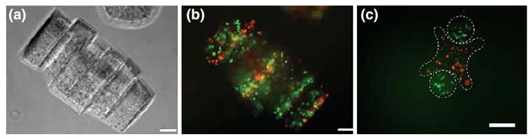
Encapsulated cells in microgel assemblies: (a) cell-laden (NIH-3T3) microgel assemblies are in phase contrast for revealing morphology; (b) fluorescence image of live/dead staining of the cell-laden microgel assemblies; (c) fluorescence image to show the microgel assembly composed of cross-shaped microgel (containing red-stained cells) and rod-shaped microgels (containing green-stained cells), (scale bars are 100 μm). Adapted from Ref. 3 with permission.
Two different cell types stained by red and green cell tracker respectively were encapsulated in cross-shaped or rod-shaped microgels (Fig. 3c) and assembled by this approach. Microscale tissue constructs composed of two cell types were fabricated, which can be readily used as co-culture system.
Acknowledgments
We thank Daniel Paik for his discussion on the introduction part. This research has been funded by the NIH, CIMIT, the Coulter Foundation, and the Institute for Soldier Nanotechnology. Yanan Du was funded by the U.S. Army Construction Engineering Research Laboratory, Engineering Research and Development Center (USACERL/ERDC).
Abbreviations
- 3D
3-Dimensional
- DPBS
Dulbecco's phosphate buffered saline
- MW
Molecular weight
- PEG
Polyethylene glycol
- UV
Ultraviolet
References
- 1.Chung SE, Park W, Shin S, Lee SA, Kwon S. Guided and fluidic self-assembly of microstructures using railed microfluidic channels. Nat Mater. 2008;7:581–587. doi: 10.1038/nmat2208. [DOI] [PubMed] [Google Scholar]
- 2.Costanzo L. Physiology. 3rd. Saunders; 2006. [Google Scholar]
- 3.Du Y, Lo E, Ali S, Khademhosseini A. Directed assembly of cell-laden microgels for fabrication of 3D tissue constructs. Proc Natl Acad Sci USA. 2008;105:9522–9527. doi: 10.1073/pnas.0801866105. [DOI] [PMC free article] [PubMed] [Google Scholar]
- 4.Khademhosseini A, Langer R. Microengineered hydrogels for tissue engineering. Biomaterials. 2007;28:5087–5092. doi: 10.1016/j.biomaterials.2007.07.021. [DOI] [PubMed] [Google Scholar]
- 5.Liu Tsang V, Chen AA, Cho LM, Jadin KD, Sah RL, DeLong S, West JL, Bhatia SN. Fabrication of 3D hepatic tissues by additive photopatterning of cellular hydrogels. FASEB J. 2007;21:790–801. doi: 10.1096/fj.06-7117com. [DOI] [PubMed] [Google Scholar]
- 6.McGuigan AP, Sefton MV. Vascularized organoid engineered by modular assembly enables blood perfusion. Proc Natl Acad Sci USA. 2006;103:11461–11466. doi: 10.1073/pnas.0602740103. [DOI] [PMC free article] [PubMed] [Google Scholar]
- 7.Nahmias Y, Schwartz RE, Verfaillie CM, Odde DJ. Laser-guided direct writing for three-dimensional tissue engineering. Biotechnol Bioeng. 2005;92:129–136. doi: 10.1002/bit.20585. [DOI] [PubMed] [Google Scholar]
- 8.Yeh J, Ling Y, Karp JM, Gantz J, Chandawarkar A, Eng G, Blumling J, 3rd, Langer R, Khademhosseini A. Micromolding of shape-controlled, harvestable cell-laden hydrogels. Biomaterials. 2006;27:5391–5398. doi: 10.1016/j.biomaterials.2006.06.005. [DOI] [PubMed] [Google Scholar]