

Abstract
The application of therapeutic ultrasound for the treatment of atrial fibrillation (AF) is investigated. The results of theoretical and experimental investigation of ultrasound ablation catheter are presented. The major components of the catheter are the high power cylindrical piezoelectric element and parabolic balloon reflector. Thermal elevation in the ostia of pulmonary veins is achieved by focusing the ultrasound beam in shape of a torus that transverses the myocardial tissue. High intensity ultrasound heating in the focal zone results in a lesion surrounding the pulmonary veins that creates an electrical conduction blocks and relief from AF symptoms. The success of the ablation procedure largely depends on the correct choice of reflector geometry and ultrasonic power. We present a theoretical model of the catheter’s acoustic field and bioheat transfer modeling of cardiac lesions. The application of an empirically derived relation between lesion formation and acoustic power is shown to correlate with the experimental data. Developed control methods combine the knowledge of theoretical acoustics and the thermal lesion formation simulations with experiment and thereby establish rigorous dosimetry that contributes to a safe and effective ultrasound ablation procedure.
Keywords: ultrasound therapy, high intensity focused ultrasound, atrial fibrillation
1.INTRODUCTION
Atrial fibrillation (AF) is identified as a leading health risk cardiac arrhythmia. A patient with AF is more likely to have a stroke than the general population. With the aging of the population in industrialized countries the rise in the prevalence of AF becomes a major health concern. The current treatments for AF are either highly invasive or intricate and time consuming, and all are accompanied by a significant risk of morbidity and mortality. This creates a backlog of individuals who would be treated if an effective and simple procedure were developed.
AF has been shown to initiate from triggers within pulmonary veins (PV) [1]. Initially it was treated by the highly invasive surgical maze procedure [2], which was primarily performed only in conjunction with other open-heart surgeries, such as valve replacement. This stimulated the development of less invasive procedures focusing on PV isolation, with catheter based radio frequency (RF) ablation leading the way. Since then catheter ablation to cure AF has developed to be the primary focus of many electrophysiologists around the world, spawning numerous variations ranging from “fire” [3] to “ice” [4]. Pappone et al. [5] developed a technique for the treatment of AF that combines both aspects of the maze and PV isolation approaches, and applied this technique to both paroxysmal and chronic AF.
While catheter-based RF ablation has been proven to be successful, the procedure is very lengthy (4-8 hours), requires a large infrastructure of support, both human and technological, and like any extended procedure in the heart, is potentially dangerous. One of the most feared complications of the RF ablation technique is pulmonary vein stenosis caused by thermal damage within the pulmonary vein, often leading to heart failure and stroke. For these reasons, RF ablation of both paroxysmal and persistent AF is employed in a limited number of the top facilities in the US and worldwide.
The experience with RF ablation has generated an accelerated interest in the exploration of other ablative energy forms. Not until recently has high-intensity focused ultrasound (HIFU) therapy [6] found its application for the treatment of AF. Geometrical focusing produces high intensity ultrasound in the focal zone that over a short time transforms into heat sufficient to denature proteins in biological tissues. Unlike RF, ultrasound propagates through blood with negligible absorption. This enables the creation of thermal tissue coagulation without requiring direct contact between catheter and target tissue, unlike RF where great care must be taken to ensure that contact is maintained between the endocardial surface and the catheter tip to avoid the formation of thrombus. Ultrasound can be focused to create a circumferential lesion around PV, eliminating the need for the time-consuming point-to-point RF ablations [7]. In addition, a judicious ultrasound frequency and power selection ensures rapid, confined heating of the targeted location at various depths without adverse effects, such as steam-pop, charring, stenosis, and thrombus formation [8]. The ability to deliver non-contact, accurate lesions in cardiac tissue makes HIFU a potentially safe and effective ablation modality for cardiac applications.
ProRhythm, Inc. (PRI) has developed an intravascular HIFU treatment for AF. The cylindrical piezoelectric transducer and inflatable balloons are the core elements of the device defining the success of PV ablation [9]. Several animal studies and extensive clinical experience has demonstrated the catheter’s ability to create circumferential lesions in atrial tissue. However, theoretical modeling of the acoustic field and experimental characterization of the catheter acoustic and thermal performance have not been reported anywhere. This work presents the theory and methods of acoustic and thermal field modeling applicable to the catheter’s cylindrical geometry. An empirical relation derived from modeling is applied to predict lesion formation trends in a tissue-mimicking phantom and improve confidence in catheter dosimetry recommendations. This work describes some of the quality control methods developed to ensure consistent circumferential power uniformity and to establish thermo-acoustic dosimetry in tissue-mimicking phantoms to provide recommendations for clinical studies
2. CATHETER DESIGN AND OPERATING PRINCIPLE
The HIFU catheter is inserted into a femoral vein and advanced to the left atrium through a guiding sheath. The location of the therapeutic catheter distal portion is demonstrated in Fig. 1. The treatment consists of the following steps. First, the sheath is advanced through the vena cava into the right atrium. Then a transseptal puncture is performed and the dilator pierces the septal wall, and the distal end of the sheath is advanced into the left atrium. After the removal of the dilator, the HIFU catheter is inserted through the sheath into the left atrium and the distal end of the catheter is inflated to a working size. The physician uses the steering mechanism to align catheter’s balloon axis with the targeted pulmonary vein (PV). Then PV ostium is ablated by applying high-intensity focused ultrasound that causes a rapid, local rise in temperature. The result is a well-defined transmural tissue necrosis that blocks the conduction of the parasitical electrical activity associated with the vein. The procedure is repeated for the rest three pulmonary veins, and the reduction of the problematic PV potentials is verified by a through-lumen spiral mapping catheter. The main advantages of HIFU are: 1) no direct tissue contact is needed for the generation of ablation lesion, and 2) the tissue is coagulated via direct heating, as opposed to energy conduction from the surface, as is the case with RF and other modalities. Coagulative necrosis of the atrial wall (3-15 mm thick) does not affect the overall muscular functioning of the heart. Alignment of the catheter with the PV preserves delicate venous tissue from ablation and reduces the risk of stenosis, commonly observed during radio frequency ablation procedures. Predominantly absorbed in the atrial wall, only a negligible fraction of ultrasound penetrates into the pericardial sack. By using an ultrasound beam, the thermal damage is highly localized. While the capillary system is destroyed in the lesion, all surrounding tissues continue to be well perfused by blood thereby supporting post-procedure tissue regeneration and rehabilitation of normal myocardial activity. Note that the transseptal puncture [10] presents a low risk to the patient, and the hole closes soon after the removal of the catheter and sheath.
Figure 1.
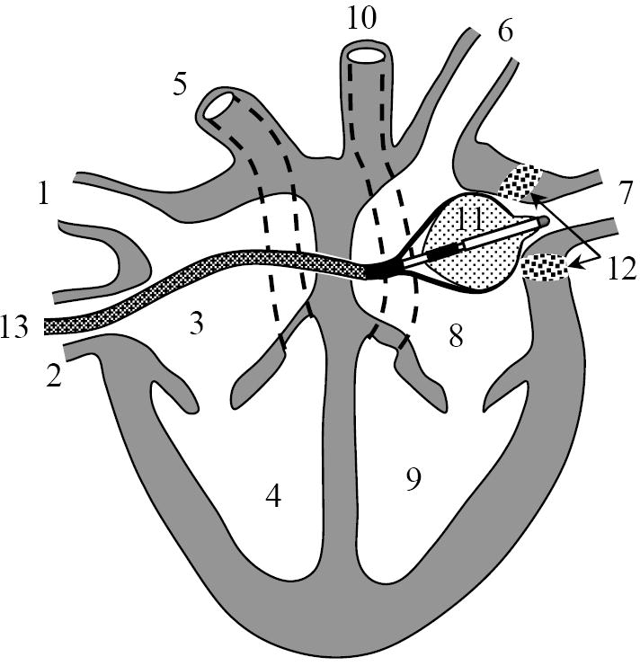
Catheter positioned in the heart. 1 - superior vena cava, 2 – inferior vena cava, 3 – right atrium, 4 – right ventricle, 5 – pulmonary artery, 6 and 7 – pulmonary veins, 8 - left atrium, 9 – left ventricle, 10 - aorta, 11 - catheter, 12 – lesion in pulmonary vein ostium, 13 – transseptal sheath.
To ensure the intravascular access to the heart the working length of the catheter is about 110 cm. The overall design of the HIFU catheter is shown on Fig. 2, where the distal end is prepared for ablation. The catheter is compatible with a 12 French guiding sheath, having an outside diameter less than 4 mm during insertion into the heart. At the same time, an effective ultrasound focusing requires an ultrasound source of dimensions significantly larger than a wavelength. An inflatable double section balloon structure in conjunction with miniature cylindrical piezoelectric transducer has been employed to satisfy these requirements. During introduction or withdrawal through the sheath the balloon is deflated as shown in Figure 3a. When positioned for the ablation of the PV ostia the inner Nylon balloon (wall thickness 8 – 30 microns) is filled with liquid, and outer proximal balloon is filled with carbon dioxide (Fig. 3b). The inflated balloons become 2 - 3 cm in diameter, and 4 cm in length, occupying the volume of 10 - 30 mL. Proximally, the carbon dioxide filled balloon forms a parabolic surface at the base of the inner balloon. When the inner balloon is inflated to a noncompliant shape the emitted cylindrical ultrasound waves are reflected by geometrically rigid parabolic interface in forward direction. The reflected ultrasonic waves propagate though thin distal wall of inner balloon into the blood and reach the atrial tissue. To enable the described functions the catheter shaft has multiple lumens allocated for the electrical power cables to transducer, fluid supply and circulation to the inner Nylon balloon, gas supply to outer balloon, and a through-lumen to deliver auxiliary mapping catheters into atrium. The catheter is also steerable through a pull wire mechanism integrated in its handle (Fig. 2, right).
Figure 2.
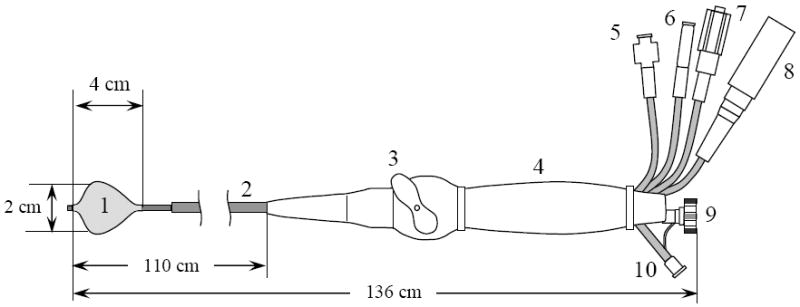
Catheter design. 1 – inner ultrasound focusing balloon with proximal parabolic reflector interface, 2 – multi-lumen catheter shaft, 3 – steering handle, 4 – catheter handle, 5 – gas inlet, 6 – liquid inlet, 7 – liquid outlet used to deflate and flow water through inner balloon, 8 – electrical power connector, 9 – through-lumen port for insertion of an electrode mapping catheter, 10 – auxiliary angiography injection port.
Figure 3.
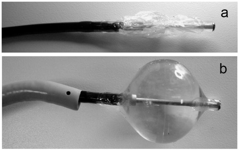
HIFU catheter balloon before and after insertion into a transvascular sheath for minimally invasive atrial access. a) Collapsed, deflated state before introduction into the sheath, b) Inflated, ready to ablate state. The transseptal sheath is shown on the left.
The basic beam-forming principles of the balloon are shown in detail in Fig. 4. The cylindrical transducer 1 radiates high-intensity acoustic waves into a liquid-filled inner balloon 2. For radiographic visualization a mixture of water and small amount of contrast agent is used. The proximal outer balloon 3 is filled with gas, forming a parabolic reflector 4 (shown by dashed line in Fig. 3). The liquid/gas interface creates a large acoustic impedance mismatch and completely reflects the incident ultrasonic waves. In all azimuthal directions the parallel rays 5 reflected from parabolic interface 4 intersect at the parabola’s focus 6. In three dimensions the locations of the foci form a ring of 2 – 3 cm diameter that is coaxial with balloon’s axis of symmetry. This focus geometry is suitable for creating a contiguous, circumferential ablation of a PV ostium with a single ablation. The combination of a cylindrical source with parabolic balloon reflector is the main enabling feature of the HIFU catheter [9]. A similar principle is employed in a construction of electromagnetic lithotripter [11] to break the kidney stones, but because the parabola’s focus coincides with the lithotripter’s axis of symmetry, in the lithotripter the rays converge in a single spot rather than in a ring.
Figure 4.
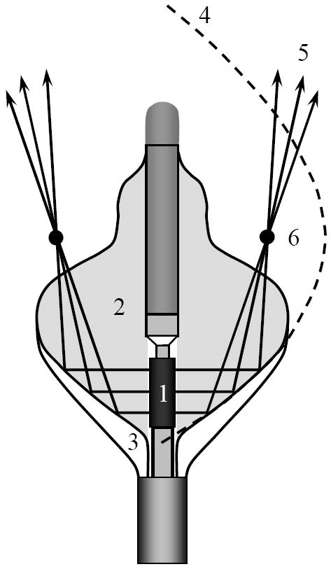
The design of the HIFU catheter: 1 –cylindrical piezoceramic transducer; 2 – liquid-filled balloon; 3 – outer gas-filled balloon section; 4 – parabolic reflective interface «liquid – gas» 5 – acoustic rays; 6 – focal point of parabola.
The ultrasound transducer 1 is made of piezoceramic PZT8 in a form of a tube 6 - 10 mm long, with an outside diameter of 2.70 mm and an inner diameter of 2.43 mm. Excited in wall thickness mode, it radiates cylindrical waves into the surrounding media. The wall thickness of the tube is 270 ± 25 microns, which corresponds to resonance frequency of 9 MHz. Transducer is backed with a coaxial brass cylinder of smaller diameter. The gap between the transducer and brass cylinder is filled with water and serves two objectives. First, the thickness of the water gap is optimized to produce maximum outgoing acoustic power. Based on the KLM [12] modeling the water layer thickness should be between 0.3 and 0.5 wavelengths in water. Second, this water layer serves to cool the piezoceramic transducer during high power operation. The transducer assembly is capable of delivering 40 watts of total acoustic power, as measured by a radiation force method with absorptive target [13]. Effective coagulation of the live muscle tissue was achieved in animal model by radiating several kJ of acoustic energy over 40 – 90 seconds.
Some of the other catheter design features are noteworthy. The liquid inside the inner balloon is degassed and maintained at pressure of 0.3 bar. Under pressure the thin Nylon film is stretched to a predefined, noncompliant, and repeatable shape. Elevated pressure also helps to avoid microbubble formation inside balloon. The outer balloon is inflated to a significantly lower pressure of 0.1 bar with carbon dioxide, which was chosen because it is soluble in blood and thus reduces the risk to the patient if catheter leaks.
3.THEORETICAL DESCRIPTION OF THE ACOUSTIC FIELD
The formation of the focus and its location with respect to balloon is illustrated by acoustic rays traced from transducer to the focal spot as shown in Fig. 4. However, such representation does not account for the effects of diffraction, which define the dimension of the focal zone and the values of the focal intensity of ultrasound. The correct method of calculation must take into account the wave nature of the acoustic field. It is convenient to simplify the calculation by considering it to be two independent problems: the radiation of divergent waves by the cylindrical transducer into an open space, and the acoustic beam formation as a result of reflection from the parabolic balloon interface.
3.1. Calculation of acoustic field radiated by a cylindrical transducer
The catheter’s transducer is a cylinder, and it is convenient to conduct a theoretical analysis in cylindrical coordinates (r, θ, z), where r is the distance from cylindrical axis, θ is the polar angle, and z is the distance along the cylindrical axis. Assume that the transducer is excited in a continuous mode with cyclic frequency ω/2π. At the acoustic power under consideration the effect of nonlinearity is negligible and the vibration of the cylinder is assumed sinusoidal ~e−iωt. For the description of the acoustic field we introduce the wave potential φ, such that vi = ∇φ, pi = −ρ0∂φ/∂t = iωρ0φ, where vi is the vibration velocity, pi is the acoustic pressure, and ρ0 is the media density at equilibrium. The index « i » in notation for acoustic pressure pi and velocity vi indicates that the acoustic wave is an incident wave with respect to balloon reflector. After reflection from the balloon interface, the scattered wave pressure and velocity are denoted by ps and vs, respectively, as described later.
The wave potential is governed by the Helmholtz equation Δφ + k2φ = 0, where k = ω/c0 is the wave number, and c0 is the speed of sound in the liquid medium. If one supposes that the surface vibration velocity distribution is independent of polar coordinate θ, the problem becomes axially symmetrical. Taking into account the axial symmetry of the problem, the Helmholtz equation can be written in the following form:
| (1) |
As a boundary condition, consider the distribution of the velocity component normal to the surface of cylindrical transducer r = a, where a is the outside radius of the cylindrical transducer. The vibration of the transducer is uniform within the transducer dimensions and absent outside the transducer:
| (2) |
where h is transducer height, and v0 is the complex amplitude of transducer surface velocity. Considering Eqs. (1) - (2), we now follow the approach described in paper [14]. If the angular spectrum is defined by the inverse Fourier transform , then equation (1) transforms into the Bessel equation . After accounting for the radiation condition (absent of waves coming from infinity) and the boundary condition, we can write the solution in the following form of the Hankel function: . The constant is found from the boundary condition that follows from Eq. (2). Taking the inverse Fourier transform and neglecting the evanescent waves in the spatial spectrum, the solution for Eqs. (1) - (2) is obtained as an integral representation:
| (3) |
Rewriting Eq. (3) for a complex amplitude of the acoustic pressure pi = iωρ0φ we get:
| (4) |
Here Ω = ωh/(2c0) is a dimensionless frequency characterizing the transducer axial wave dimension. In our case the length of transducer h = 6 mm and its wave dimension is fairly large, Ω ≈ 114, which points to a small divergence of the acoustic field in an axial direction. There is no analytical solution to the integral (4), however its numerical evaluation is straightforward.
In order to calculate the value of acoustic pressure in Eq. (4) it is necessary to know the amplitude of transducer surface velocity v0. Because direct experimental assessment of v0 is not feasible, an estimate from hydrophone measurements or from total acoustic power P should be used. Choosing to use the latter option, it is necessary to find the relation between v0 and P for the considered transducer. Total acoustic power produced by the transducer is defined as an integral over the radiating surface of the normal component of acoustic intensity vector I = 〈pivi〉: P = ∫I dS, where vi is the normal component of surface velocity vi, and the brackets 〈…〉 indicate averaging over a wave period. When using a complex representation for the amplitudes of velocity and pressure the acoustic intensity is written as I = Re(pivi*/2), where the asterisk denotes the complex conjugate. Because the amplitude of the transducer velocity is assumed constant and real within the transducer’s dimensions: vi = v0, then we arrive at the following for a cylindrical source: . Substituting pi from Eq. (4) and integrating over z, we find the relation between surface velocity v0 and total acoustic power P:
| (5) |
Note, that if Ω → ∞ the above equation becomes a table integral , which yields an expected value of total acoustic power in case of planar approximation P = (ρ0c0v02/2)×2πah, i.e. the product of the acoustic intensity and the transducer area. It not difficult to verify that this approximation produces an error of less than 0.1% if Ω ≥ 100 , and therefore it can be reliably used.
3.2. Calculation of acoustic field after reflection from parabolic mirror
Outside the transducer the acoustic field is a superposition of incident and scattered (reflected) waves p = pi + ps. Incident wave pi is given by Eq. (4) and is known. On a soft acoustic reflector the boundary pressure has to go to zero, p∣S = 0 , and the acoustic pressure of the reflected wave is given by simple inversion of the incident pressure: ps∣S = −pi∣S. This can be modeled by placing additional acoustic sources on reflective surface S. By doing so, the problem of reflection is replaced by a problem of radiating wave ps by a reflective surface S. For an exact solution the pressure normal derivative ∂ps/∂n∣S needs to be known in addition to a pressure ps∣S. Following the theorem of Kirchhoff-Helmholtz, the radiated field is given by a convolution surface integral of ps∣S and ∂ps/∂n∣S [15]. The problem is that ∂ps/∂n∣S is not known and calculation of ∂ps/∂n∣S is not a trivial task due to reflector curvature. However, if the curvature radius of the radiating surface is much bigger than the wavelength (as in the present case), then the Kirchhoff approximation [16], describing acoustic field scattered from large scale inhomogeneities, can be used to calculate the reflected pressure field with a very good accuracy. According to this approach, the reflection from a non-planar surface is considered as a reflection from a plane tangential to the surface locally. Then at the free boundary the normal component of the spatial pressure derivative can be easily calculated: ∂ps/∂n∣S = −∂pi/∂n∣S. The same approximation can be written in a different form that is more convenient for numerical calculations. For a quasi-planar source surface the Kirchhoff-Helmholtz integral becomes a Rayleigh integral, that accounts for either ps∣S or ∂ps/∂n∣S. In the present problem, the normal derivative of pressure on the reflector is unknown. For this reason, it is convenient to use the Rayleigh integral that includes ps∣S:
| (6) |
where r is the coordinate of observation point, and R = ∣r − r′∣ is the distance between the observation point and reflector surface element dS′. Because for all points r′ ∈ S it is true that ps(r′) = −pi(r′), the calculation of the reflected wave ps(r) is achieved by a straightforward integration of the incident wave pressure pi(r′) over reflector surface.
3.3. Modeling results
The use of equations (4) and (6) presents a solution of the problem under consideration. The focal acoustic field created by the HIFU catheter can be calculated based on a numeric algorithm derived from these equations. An example of the acoustic field focusing is shown in Fig. 5. The insert shows the distribution of the acoustic field in a 5×10 mm rectangular region in a plane (r, z). It can be seen that focused region is rather small, 0.5 mm in transverse and 2–3 mm in the longitudinal direction. The intensity of the spatial side lobes is negligible compared to the peak focal intensity of 250 W/cm2, obtained for a list of input parameters provided in the caption to Fig. 5. In practice the focal intensity is expected to be lower due to non-ideal variations in the balloon parabolic reflector, the associated field aberrations, and absorption in cardiac tissue. However the modeling results confirm that the HIFU catheter is capable of creating the focal pattern with an ultrasound intensity sufficient to produce thermal coagulation of the tissue.
Figure 5.
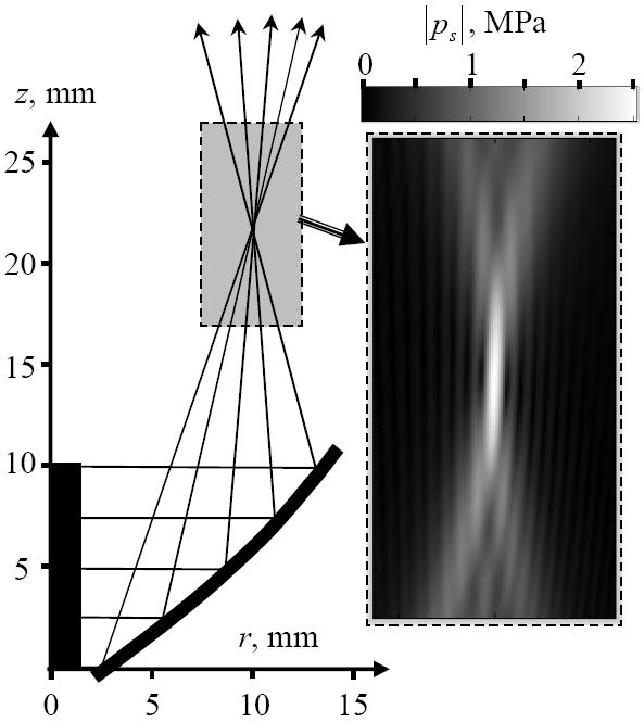
Typical results of the acoustic field modeling. The geometry of the source and a tracing of the acoustic rays are shown on the left. The region of interest is shown by the gray rectangle. The amplitude of the maximum acoustic pressure in the region of interest is magnified on the right. The gradation in gray scale is linear as shown on the colorbar. The source acoustic power is 40 W, transducer height 10 mm, diameter 2.7 mm.
4. STUDY OF THERMAL IMPACT
4.1. Thermal field modeling
The HIFU catheter creates thermal effects when the ultrasound is absorbed by the tissue. The volumetric density of thermal sources Q is defined from energy conservation principle Q = −div I, where I is the acoustic wave energy flux vector (intensity). The latter can be written using the calculated parameters of the acoustic wave, reflected from the parabolic balloon interface: I = Re(psvs*)/2. This implies first calculating the acoustic pressure on the tissue boundary using Eq. (6), and then applying the same Eq. (6) to calculate the pressure distribution inside the tissue. The different speed of sound and attenuation in tissue need to be taken into account, and the wave vector becomes a complex number k = ω/c + iα, where c is the speed of sound, and α is the attenuation coefficient in atrial tissue. A less rigorous method of calculating Q assumes planar wave propagation, for which Q = 2α · I where I = ∣ps∣2/(2ρ0c0) is the absolute value of the acoustic intensity.
The temperature distribution in live tissue in presence of thermal sources can be described by the bio-heat transfer equation [17]:
| (7) |
Here ρ and Cv are the density and specific heat of tissue, respectively, T is the temperature of the tissue, t is time, Δ = r−1 ∂/∂r (r∂/∂r) + ∂2/∂z2 is Laplacian for an axially symmetric problem, wb is the blood perfusion coefficient, Cb is the specific heat of blood, Tb is the temperature of the blood, κ is thermal conductivity, and the heat source Q is approximated to be Q ≈ 2α · I The values for parameters in Eq. (7) are as follows: ρ = 1060 kg/m3, Cv = 3720 J/(kg·°C), Cb = 3770 J/(kg·°C), wb =13.5 kg/(m3·c) [8] , Tb = 37°C, κ = 0.5 W/m·°C), α = 13 Neper/(m·MHz) [18]. Note that at 9 MHz the characteristic length of ultrasound attenuation in tissue is α−1 ≈ 8.5 mm, which roughly corresponds to the thickness of the atrial wall. This was one of the defining factors for the selection of the catheter’s operating frequency. The characteristic times of perfusion and diffusion are: tperf = ρCv/(wbCb) and tdiff = L2 ρCv/κ, where L is the dimension of the heated region. Substituting numeric values we get: tperf ≈ 80s and tdiff ≈ 8 × L2, where L is measured in millimeters. The desired heated region spans from 1 to 4 mm, yielding tdiff in the range of 8 to 130 s, while the typical ablation time tHIFU is from 40 to 90 s. Clearly, tHIFU ≥ tdiff, tperf, indicating that thermal diffusion processes play an important role.
Equation (7) was solved using finite difference method of Crank-Nicolson described elsewhere [19]. The region of thermal coagulation was determined based on thermal dose defined as [17, 21]:
| (8) |
where the temperature T is in Centigrade, and parameter R is piecewise constant: R = 0.25 if T < 43°C and R = 0.5 if T ≥ 43°C . It was assumed that thermal damage occurred when D ≥ Ddamage, where the threshold value is Ddamage= 1.44×10⁴ s [20].
The temperature and corresponding thermal dose D were calculated for a range of acoustic powers from 20 to 50 watts. The area of calculations constituted a rectangle (r, z), located distal to the catheter balloon as shown in Fig. 6. The bottom boundary was assumed to coincide with blood/tissue interface. Tanking into account continuing blood circulation in atria during ablation, the temperature at that boundary was assumed constant 37 °C. At other boundaries the adiabatic condition of zero thermal flux through boundary was assumed. The lesion was positioned at the center of calculated region to minimize the effect of the boundaries. The characteristic event time τ, required to achieve certain thermal damage (where D ≤ Ddamage) or lesion growth to certain depth L, was chosen to quantify the formation process. For example, the time when lesion reaches 4 mm depth could be considered a desired ablation time. The regression analysis of the simulated lesion growth at different acoustic power yield the following approximation:
Figure 6.
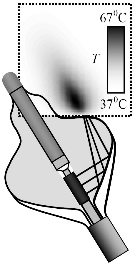
An example of temperature field modeling in square region 20×20 mm (outlined by dashed line). The temperature is shown after 23 s of ablation and acoustic power of P = 40 W. A constant temperature of 37 °C was assumed at the bottom boundary.
| (9) |
where τ0 is the characteristic event time at nominal acoustic power P0 = 37 W. It appeared that τ0 strongly depends on desired L and on the diameter of focal ring created by catheter balloon reflector. At the same time the regression coefficient β was not sensitive to the respective parameters. Using a least-square method in a range of acoustic powers 20 W ≤ P ≤ 50 W we obtained β = 2.35± 0.05, which is higher than β =1 , expected in absence of thermal conduction where thermal coagulation occurs at a critical temperature Tthreshold ~ Pτ that is proportional to the product of applied acoustic power and ablation time. Higher value of obtained regression coefficient β is reconciled by the fact that we used thermal dose (8) instead of temperature to define the boundaries of lesion, and because the outward thermal flux from ablation region is not negligible. Thus, the empirically derived dependence (9) accounts for the effects of thermal perfusion, diffusion, and the specifics of the device design over a range of studied acoustic powers.
4.2. Experimental evaluation of thermo-acoustic dosimetry
The lesion formation experiments were performed in a polyacrylamide tissue-mimicking phantom, which closely approximates soft tissue physical properties [21, 22]. The principal difference between the gel model and tissue is the absence of perfusion. As noted above, the characteristic perfusion time tperf ≈ 80 s is larger than tHIFU for small balloon configurations (40 s) and is comparable for larger balloons (90 s). Therefore the effect of perfusion is important to take into account for longer ablation times, while the effect of thermal conduction tdiff ≈ 4 – 130s affects lesion growth even at relatively short ablation times for all balloon configurations. Because thermal conduction properties of gel are comparable to those of the soft tissue, the dependence (9) enables the comparison of the thermo-acoustic efficacy of different catheters by reducing experimental data over a limited range of power to a single parameter τ0, the characteristic lesion formation event time at nominal power. In contrast with animal studies [23], where lesion parameters are obtained after histological examination and experimental data generally contains a lot of variation, study of lesion growth in gel could be conducted as a function of time with immediate results. The gel remains optically clear at ambient temperature and permanently becomes opaque when the contained proteins denature at about 70°C during high power ultrasound ablation. The transformation in gel first occurs in the spots where intensity of the ultrasound field is the highest. With this method it was possible to conduct in situ observation of the thermal initiation and growth of a lesion, while measuring dimensional parameters as a function of time. An example of lesion obtained using HIFU catheter is shown in Fig. 7.
Figure 7.
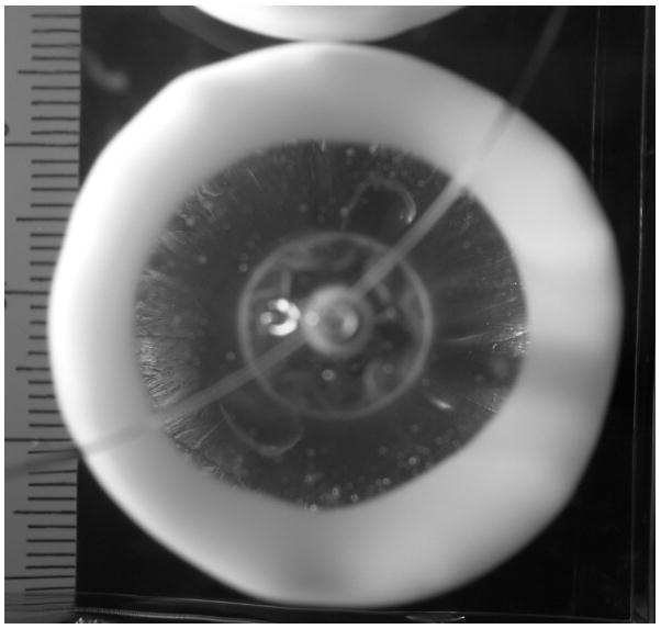
Formation of the 30 mm wide circular lesion in gel by the HIFU catheter (top view; for catheter orientation see Fig. 4).
Lesion formation experiments were conducted in gel using three groups of randomly selected catheters of different sizes. Within a single group all catheters had the same dimensions and any differences in ultrasound focal field patterns are due to manufacturing variations, defects in transducer, and/or deformation of balloon reflector shape. The diameter of the ablation ring was different for each group, being 20, 25, and 30 mm respectively.
The experiments were conducted by placing the gel sample in warm water at 37°C and positioning the catheter in contact with gel surface. A video camera (Sony, TRV 615) was positioned underneath the gel to film the lesion development during ablation. For some catheters the ablation ring was not quite uniform azimuthally (possibly due to a non-uniformity in the cylindrical transducer vibration pattern), which resulted in a spread of the characteristic times for different catheters. Because of intrinsic non-uniformities, the characteristic times τ(1) of lesion nucleation and τ(2) of lesion circumferential closing typically were different. Three lesion formation events were recorded: 1) nucleation time defined as the first visual appearance of the opaqueness in the gel (at t = τ(1)); 2) closed circle time defined as a visual closure of the lesion around the balloon (at t = τ(2)); and 3) the time of lesion growth to L = 4 mm depth. (at t = τ(3)). The applied electrical power was controlled to provide a range of acoustic powers between 10 and 60 watts.
Figure 8 shows the experimental lesion closing time τ0(2) at different acoustic powers. As expected, this characteristic time decreases as power increases. The lines approximating the experimental data use Eq. (9) assuming fixed value of β =2.35, as determined by numerical simulation. There is a decent agreement between the fitted curves and the experimental data. The time of thermal coagulation decreases as the diameter of focal ring decreases.
Figure 8.
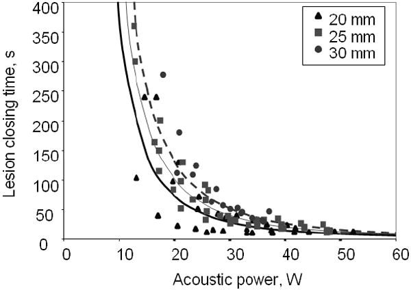
Time of lesion closing τ0(2): as a function of applied acoustic power W for different catheters with balloons of different diameters (labeled above).
The objective of the measurements was to obtain trends between the catheter groups and predict lesion formation time as a function of radiated acoustic power. The nonuniformity of lesions, subjectivity of observers in identification of events, and other experimental errors resulted in relatively large scatter in data. This warranted the use of Eq. (9) with only one variable τ0, the characteristic lesion formation event time at nominal power P = P0, which resulted in an accurate fit to the data with a limited amount of catheters in each group. The results are shown in the Table. It is clear that lesion nucleation requires only a few seconds while it takes several tens of seconds to complete circumferential lesion formation. The lesions of smaller diameter form faster, consistent with the higher acoustic intensity being distributed over a smaller volume. Therefore, by adopting Eq. (9) with β =2.35 to process scattered, heterogeneous experimental data it was possible to determine the characteristic lesion formation time for a group of catheters of similar design and to permit explicit detection of catheter dependent lesion formation differences.
TABLE.
Characteristic time of desired event for a nominal value of acoustic power P0 = 37 W (see description in text).
| Balloon diameter (mm) | Characteristic time (s) | ||
|---|---|---|---|
| τ0(1) Nucleation time | τ0(2) Lesion closing | τ0(3) Lesion thickness L =4 mm | |
| 20 | 5.2 ± 1.1 | 17.6 ± 3.7 | 27.6 ± 6.1 |
| 25 | 5.7 ± 1.8 | 24.7 ± 6.5 | 37.9 ±8.5 |
| 30 | 6.2 ± 1.9 | 31.7 ±10.0 | 49.5 ± 7.2 |
| Average over all catheters | 5.6 ± 1.8 | 23.6 ± 6.3 | 36.4 ± 7.4 |
5. CONCLUDING REMARKS
The HIFU catheter investigated in this paper is designed as an effective medical instrument for treatment of atrial fibrillation. The focused, high-intensity ultrasonic field is created by an inflatable balloon structure at the distal end of an intravascular catheter. The ability to produce a focused ultrasound field with the inflated balloon and to maneuver though the vasculature in a deflated state is one of the important features of the described HIFU catheter. The acoustic field created by HIFU catheter also differs from other therapeutic ultrasonic devices. The source is a miniature cylindrical transducer radiating divergent acoustic wave that is reflected from the parabolic balloon interface to form a forwardly-directed annular focus in tissue. Unlike classical single point focusing, the HIFU catheter balloon focuses ultrasound in a narrow ring of 20 to 30 mm in diameter and an axial length of 6 – 10 mm in the direction of beam propagation (Fig. 5). Consequently, complete circumferential and transmural lesions in PV ostia are achievable with a single application of ultrasound and without direct contact between balloon and atrial tissues. This constitutes an important advantage over other ablative technologies.
The method of ultrasound field calculation and its application to thermal dosimetry has been presented. Numerical models provide a description of the HIFU catheter’s acoustic field features and enables catheter design optimization. An empirical relationship between the characteristic time of lesion formation and the acoustic power has been derived from numerical simulations and was used in experimental data analysis. The ablation in an optically transparent tissue-mimicking polyacrylamide gel phantom was used to experimentally study the geometry of lesion formation as a function of time. The results demonstrate the HIFU catheter’s ability to produce concentric lesions, applicable to the PV isolation procedure. The diameter of circular lesions and characteristic lesion-formation time are defined by the shape of catheter balloon and the delivered acoustic power. These dependencies enable the establishment of practical recommendations for the choice of acoustic power and total ablation time required in tissue using HIFU catheter of different balloon configurations and sizes to create complete circular lesions. These recommendations will help to improve the efficacy and safety of the therapeutic ultrasound ablation procedure.
Experiments conducted in the tissue-mimicking gel phantom brought to light some characteristic features of lesion formation, not otherwise predicted by the axially symmetric numerical model. It appears that the circular lesions are not uniform in number of cases, with certain sections growing faster and other sections experiencing a delay in nucleation and growing more slowly, often resulting in non-uniform circumferential lesions. These variations are caused by a non-uniform ultrasound focus intensity distribution over the circumference. The deformation of the balloon reflector and imperfection in transducer surface vibration can be the major cause of such variations. Theoretical analysis of these features can be conducted within the scope of the proposed acoustic and temperature field modeling.
Acknowledgments
This research was funded by ProRhythm, Inc. One of the authors (OAS) was supported by grants RFBR 08-02-00368, ISTC 3691 and NIH R01EB007643. Authors extend their gratitude to Dr. Peter Kaczkowski for his help with polyacrylamide gel identification and processes, and to Dr. Vera Khokhlova for a useful discussion of nonlinear effects.
Contributor Information
Y.D. Sinelnikov, Email: yegor@prorhythm.com.
T. Fjield, Email: tfjield@alum.mit.edu.
O.A. Sapozhnikov, Email: oleg@acs366.phys.msu.ru.
References
- 1.Haissaguerre M, Jais P, Shah DC, et al. Spontaneous initiation of atrial fibrillation by ectopic beats originating in the pulmonary veins. N Engl J Med. 1998;339:659–666. doi: 10.1056/NEJM199809033391003. [DOI] [PubMed] [Google Scholar]
- 2.Cox J, Canavan T, Schusasler R. The surgical treatment of atrial fibrillation II: Intraoperative electrophysiologic mapping and description of the electrophysiologic basis of atrial flutter and atrial fibrillation. Thorac Cardiovascular Surg. 1991;101:406–426. [PubMed] [Google Scholar]
- 3.Keane D, Reddy V, Ruskin J. Emerging concepts on catheter ablation of atrial fibrillation from the Tenth Annual Boston atrial fibrillation symposium. J of Cardiovascular Electrophysiology. 2005;16(9):1025–1028. doi: 10.1111/j.1540-8167.2005.00270.x. [DOI] [PubMed] [Google Scholar]
- 4.Tse H-F, Sin P-Y, Siu C-W, Tsang V, Lam CLK, Lau C-P. Successful pulmonary vein isolation using transvenous catheter cryoablation improves quality-of-life in patients with atrial fibrillation. PACE. 2005;28:421–424. doi: 10.1111/j.1540-8159.2005.50001.x. [DOI] [PubMed] [Google Scholar]
- 5.Pappone C, Oreto G, Rosanio S, et al. Atrial electroanatomic remodeling after circumferential radiofrequency pulmonary vein ablation: efficacy of an anatomic approach in a large cohort of patients with atrial fibrillation. Circulation. 2001;104:2539–2544. doi: 10.1161/hc4601.098517. [DOI] [PubMed] [Google Scholar]
- 6.Bailey MR, Khokhlova VA, Sapozhnikov OA, Kargl SG, Crum LA. Physical mechanisms of the therapeutic effect of ultrasound (A review) Acoustical Physics. 2003;49(4):369–388. [Google Scholar]
- 7.Diederich CJ, Nau WH, Taylor K, Maguire MA, Picazo G, Gangu M, Lesh MD. Ultrasound catheters for circumferential cardiac ablation. Proc SPIE Conf Thermal Treatment of Tissue with Image Guidance (SPIE, San Jose, CA) 1999;3594:26. [Google Scholar]
- 8.Zimmer JE, Hynynen K, He S, Marcus F. The feasibility of using ultrasound for cardiac ablation. IEEE Transactions on Biomedical Engineering. 1995;42(9):891–897. doi: 10.1109/10.412655. [DOI] [PubMed] [Google Scholar]
- 9.Fjield T, Harhen EP, Acker DE, Lopath PD. Thermal treatment methods and apparatus with focused energy application. 7326201. United States Patent. 2008 Feb 5;
- 10.Brockenbrough E, Braunwald E. A new technique for left ventricular angiography and transseptal left heart catheterization. Am J Cardiol. 1960;6:219–231. [Google Scholar]
- 11.Lingeman JE, Zafar FS. Lithotripsy systems. In: Smith AD, Badlani GH, Bagley DH, et al., editors. Smith’s Textbook of Endourology. St Louis, Mo: Quality Medical Publishing; 1996. pp. 553–589. [Google Scholar]
- 12.Krimholtz R, Leedom DA, Matthaei GL. New equivalent circuits for elementary piezoelectric transducers. Electronics Letters. 1970;6(12):398–399. [Google Scholar]
- 13.Beissner K. Ultrasonic power measurement using sound radiation force. Acustica. 1985;58(1):17–26. [Google Scholar]
- 14.Alekseev VK, Lependin LF. Acoustic field of a pulsating ring on a cylinder. Akusticheskii Zhurnal. 1967;14(4):126. in Russian. [Google Scholar]
- 15.Pierce AD. Acoustics: An introduction to its physical principles and applications. NY: Acoust. Soc. Amer; 1991. [Google Scholar]
- 16.Brekhovskikh LM. Diffraction of waves at an uneven surface. J Exptl -Theoret Phys (USSR) 1952;23(3):275–288. [Google Scholar]
- 17.Pennes HH. Analysis of tissue and arterial blood temperatures in the resting human forearm. J Appl Physiol. 1948;1:93–122. doi: 10.1152/jappl.1948.1.2.93. [DOI] [PubMed] [Google Scholar]
- 18.Goss SA, Johnson RL, Dunn F. Comprehensive compilation of empirical ultrasonic properties of mammalian tissues. J Acoust Soc Am. 1978;64(2):423–458. doi: 10.1121/1.382016. [DOI] [PubMed] [Google Scholar]
- 19.Crank J, Nicolson P. A practical method for numerical evaluation of solutions of partial differential equations of the heat conduction type. Proc Camb Phil Soc. 1947;43:50–67. [Google Scholar]
- 20.Sapareto SA, Dewey WC. Thermal dose determination in cancer therapy. Int J Radiat Oncol Biol Phys. 1984;10(6):787–800. doi: 10.1016/0360-3016(84)90379-1. [DOI] [PubMed] [Google Scholar]
- 21.Howard S, Yuen J, Wegner P, Zanelli CI. Characterization and FEA simulation for a HIFU phantom material. Proc of IEEE Ultrasonic Symposium. 2003:1270–1273. [Google Scholar]
- 22.Lafon C, Zderic V, Noble ML, Yuen JC, Kaczkowski PG, Sapozhnikov OA, Chavrier F, Crum LA, Vaezy S. Gel phantom for use in high-intensity focused ultrasound dosimetry. Ultrasound in Medicine and Biology. 2005;31(10):1383–1389. doi: 10.1016/j.ultrasmedbio.2005.06.004. [DOI] [PubMed] [Google Scholar]
- 23.Nakagawa H, Yamanashi WS, Pitha JV, Arruda M, Wang X, Otomo K, Beckman KJ, McClelland JH, Lazzara R, Jackman WM. Comparison of in vivo tissue temperature profile and lesion geometry for radiofrequency ablation with a saline-irrigated electrode versus temperature control in a canine thigh muscle preparation. Circulation. 1995;91:2264–2273. doi: 10.1161/01.cir.91.8.2264. [DOI] [PubMed] [Google Scholar]