Abstract
The design and initial test results of a new passively suspended Tesla type LAVD blood pump are described. CFD analysis was used in the design of the pump. Overall size of the prototype device is 50 mm in diameter and 75 mm in length. The pump rotor has a density lower than that of blood and when spinning inside the stator in blood it creates a buoyant centering force that suspends the rotor in the radial direction. The axial magnetic force between the rotor and stator restrain the rotor in the axial direction. The pump is capable of pumping up to 10 liters/min at a 70 mmHg head rise at 8000 RPM. The pump has demonstrated a normalized index of hemolysis level below .02 mg/dL for flows between 2 and 9.7 L/min. An inlet pressure sensor has also been incorporated into the inlet cannula wall and will be used for control purposes. One initial in vivo study showed an encouraging result. Further CFD modeling refinements are planned as well as endurance testing of the device.
Keywords: TESLA Pump, LAD, Blood Pump
Introduction
Nikola Tesla is perhaps best known for his contributions to the field of electricity and magnetism; however, on October 21st, 1909, Nikola Tesla filed a patent (U. S. patent #1,061,142, May 6th, 1913) for a pump that used smooth rotating disks inside a volute housing.1 Although there have been many attempts to utilize the pump in commercial applications, it has never found wide spread use. There are several features of the basic design that make it attractive for a blood pump application. Our research group is not the first to use the Tesla type pump as a blood pump, but we have developed a pump with a unique passive suspension system that has several desirable features and potential advantages over a bladed design:2-5 1) Reduced cost due to the simplicity of manufacturing and assembly - For the bladed design it is a challenge to build a closed type bladed impeller with two shrouds on both sides while maintaining smooth surfaces and connections in the blade/shroud areas. 2) Reduced turbulent flow stresses compared to the tip of the blade where the flow enters and exits the bladed impeller. 3) Absence of cavitation conditions in the Tesla impeller. 4) More gentle handling of blood due to the slow momentum change in the fluid (similar to moving along a very long blade). 5) More uniform force - there is no force generated by a blade passing the pump outlet. In general, all of these features are due to the fact that the useful work of the Tesla pump is spread over a larger surface area, thus reducing peak low-pressure (and cavitation), and mean-shear and turbulence generation.
Materials and Methods
Pump Description and Operating Principle
The pump consists of a uniquely suspended rotor that employs multiple disks to form the Tesla impeller.1, 6-8 The Tesla impeller is a form of centrifugal impeller that uses fluid viscous shear to affect energy/momentum transfer between the fluid and parallel disks. Tesla described this principle as adhesion and propulsion utilizing viscosity.1 The flow is limited to the boundary layer conditions created between two parallel disks.9 This concept is also utilized on the Biomedicus Bio-Pump® (Medtronic, Minneapolis, MN).10
The most unique feature of our design is the rotor suspension method. The rotor is passively suspended in the axial direction by the rotor and stator axial magnetic force. Referring to Figures 1, 2 and 3, in the radial direction, the primary centering force is a buoyant force6-8 that acts in addition to the conventional hydrodynamic, magnetic, gravitational, and frictional forces. The rotor buoyant force is created by the centrifugal force of the rotating blood. When a rotor (impeller) of density ρ1, rotates in an infinite liquid of density ρ2, and ρ1 < ρ2, the rotor and liquid interaction develops a rotor body force, Fc, that is inwardly directed. This force is equal to
| (Eqn 1) |
where Fc is the positive inward acting force for the rotor suspension in two degrees of freedom (x and y) acting on the rotor in the direction perpendicular to the axis of rotation, Δρ =ρ2 - ρ1, ω is the angular velocity of the rotor about its axis of rotation, Rc is the radius of displacement of the rotor from the central axis, and V is the volume of the rotor. Since Fc is directly proportional to the difference between the rotor and blood density it is advantageous to minimize the rotor density. For this reason the rotor body is constructed from PEEK (polyetheretherketone). It has an excellent strength to weight ratio and has demonstrated good biocompatibility. Neodymium-iron magnets are used to minimize magnet mass. The current system uses titanium discs but future rotors will use all PEEK construction.
Figure 1.
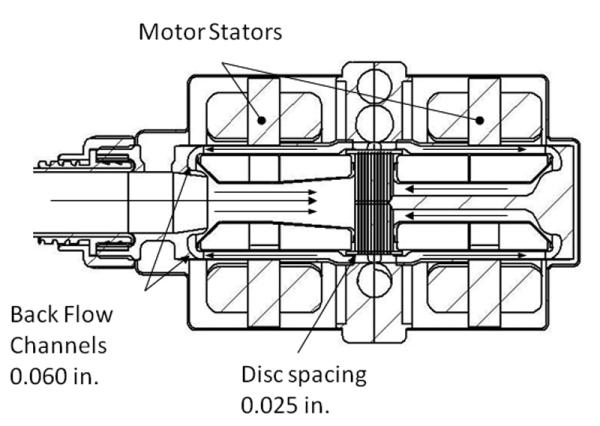
Cross sectional schematic drawing of the motor and pump design. Critical internal dimensions are shown, arrows indicate flow direction. The overall outside diameter of the prototype pump is 2 in. and the housing length is 3 in.
Figure 2.
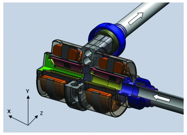
Solid model of the complete pump assembly. The inlet and outlet cannula are flexible wire wound grafts (not shown).
Figure 3.
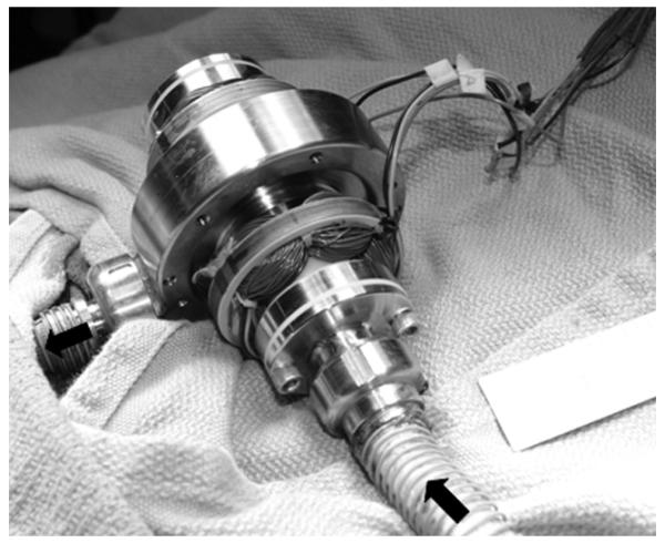
Picture showing extracorporeal placement of device in animal model.
The attraction of the rotor magnets to the stator iron creates a negative stiffness which opposes the buoyant centering stiffness. Finite element analysis of the motor magnetics was used to estimate the magnetic radial stiffness as 2.59 N/mm and a custom fixture was constructed to measure the rotor stator magnetic radial force. This force was found to be a linear function of radial displacement and independent of rotor speed. The stiffness value was 2.17 N/mm.
A simplified analysis using only the buoyant and radial magnetic body forces shows that, if rotor speed remains above 6000 RPM, it results in a buoyant force radial stiffness of 3.03 N/mm thus achieving a net positive stiffness allowing the rotor to levitate. Angular stiffness about the x and y axes can be treated as independent radial stiffness in the two stators and rotor magnet sets.
The pump impeller is a closed type with shrouds on both sides. Each shroud is a shell structure with sealed air pockets containing the motor magnets. The flow from the pump inlet is drawn through the impeller center bore to the impeller entrance and exits the impeller at a higher pressure. The majority of the flow from the impeller goes to the pump outlet. The remainder is directed to the front and backflow channels and back to the center bore where the pressure is lower. Clearances in the backflow channels are such that during startup, contact between the impeller and the housing can occur only in the restrictor (end) regions where the tangential velocity of the contact is lower, reducing the tribological and hemolytic damage. The rotor radial displacement is thereby limited to 1 mm.
The rotor is restrained in the axial (z) direction by the magnetic attractive force of the stator iron and rotor magnets. Finite element analysis predicts an axial magnetic stiffness of 11.5 N/mm. Thus when the rotor and stator are properly aligned there should be no contact under operating conditions.
Once the impeller is rotating above a minimum speed, Fc becomes larger than the radial magnetic force and the system has positive stiffness in all directions and all degrees of freedom, and becomes passively suspended.
Hydrodynamic forces due to inlet blood flow and the momentum change from the axial to the radial direction creates a reaction force in the rotor in the axial direction away from the inlet port. The force causes a flow-dependent axial displacement which is partially offset by placement of the stators. Other internal destabilizing forces are the result of deviations from symmetry conditions around the impeller in terms of pressures, flows and mechanical imbalance or asymmetry.
CFD Design Analysis
Computational fluid dynamics (CFD) was used to evaluate several design iterations of the pump before the first prototype was manufactured. The volute geometry was explored and a double volute appeared to be the most efficient design while providing symmetrical loading on the rotor. Other fundamental properties such as disc diameter, number of discs and disc spacing were also explored. The CFD analyses were performed using an in-house CFD solver primarily developed for turbomachinery analysis. The design analyses used structured overset meshes containing approximately four-million grid points. Steady simulations were performed on several pump design variants over a wide range of operating conditions likely to be encountered after implantation, using a Newtonian approximation for blood. Calculations were performed at rotation rates of 6500, 6750 and 7000 RPM and a range of flow rates from 2 to 7 L/min.
Simulation results were primarily confined to the inlet annulus and rotor plates. Figure 4 shows a mesh slice through the device center for the original and optimized designs as well as the CFD results for the area.
Figure 4.
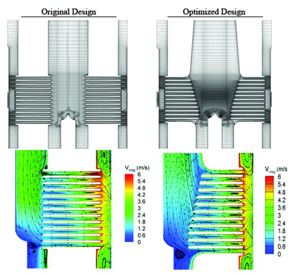
The top illustration is the CFD meshes showing a slice through the pump centerline for the original design and the CFD optimized design. The lower illustrations show the circumferentially averaged velocity magnitude contours and in-plane streamlines for the initial design and the CFD optimized design.
The plate inlet region was modified based on observation of flow separations occurring at the leading edges of the upper plates. Figure 5 shows circumferentially averaged velocity magnitude contours and 2D in-plane streamlines for the two design variants at the nominal design condition of 6 L/min at 6750 RPM. It was observed that large flow separations occurred on the underside of the upper plates in the original design, effectively altering the plate leading edge shape and blocking the upper gap flow. The tapered leading edges of the optimized design alleviated these separations by reducing the angle which the fluid must traverse to enter the upper gaps.
Figure 5.
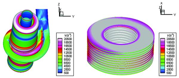
Contours of scalar wall-shear rate occurring on the outer housing and on the plates of the optimized design.
Further hydrodynamic improvement was accomplished through the diffuser added to the upper inlet annulus. The diffusive section resulted in a reduction in the peak fluid velocity entering the plate region of the annulus. The peak through-flow velocity was reduced from 2.8 m/s down to 2.3 m/s as observed in Figure 4. This reduction in annulus velocity allowed the fluid to transition from the axial annulus flow to the radial plate gap flow without encountering significant leading edge separation.
Reshaping the leading edge region resulted in a more uniform flow rate through the gaps. The reshaping process ensured that all of the gaps would contribute to the pumping process as opposed to the original design where the upper gaps suffered from substantial blockage.
Reshaping the plate inlet region increased the pump head rise by 18%. However, this increased head rise came at the cost of an additional 7% power requirement for the motor. Overall, the net pump efficiency was improved by 11% to a value of 15% at a flow rate of 5 L/min and 80 mmHg. Finally, it was observed that the optimized design resulted in a doubling of the backflow. This had the desirable effect of reducing the potential for flow stagnation induced thrombus formation in the backflow region.
Figure 5 shows the scalar wall-shear rates occurring on the outer housing and on the plates for the optimized design. The peak shear rates observed in the simulation data were approximately 30,000 s−1. The regions of high wall-shear occurred primarily within the plate gaps, at the volute entrances and in the curved regions of the backflow paths.
The CFD predicted pump performance curve in nondimensional variables head coefficient ,Ch = [(ΔP/ ρ)/(ω2D2)], vs. capacity coefficient, Cq =[(Q)/(ωD3)], where ΔP is the pressure rise, Q is the volumetric flow rate, and D is the inlet diameter as shown in Figure 6. It shows that the curves for each RPM value collapse to a single nondimensional curve, which leads to the following conclusions: 1) the CFD model predicts that Ch is a function of only Cq, which means that second effects, e.g., due to Reynolds number and surface roughness, are either not important or are not resolved by the model; and 2) scaling to other RPM values can be directly computed from the results at RPM = 6500, 6750, or 7000.
Figure 6.
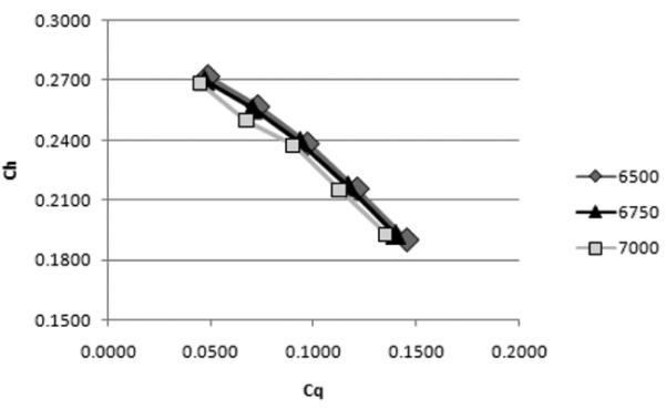
Pump performance curves, a-dimensional H vs Q. (top) and b-non-dimensional CH vs. CQ curve (bottom, from CFD simulations.
Control
The pump rotor is driven by a three-phase brushless DC motor. The control unit was designed and manufactured by Minnetronix (St. Paul, MN). Sinusoidal commutation with sensorless field oriented control is used to reduce torque ripple.
A pressure sensor has been developed using a strain gage bonded to an area of the pump inlet port that is machined to .038 mm thick.11 This sensor is designed to detect potential ventricular suction events. Finite element modeling (FEA) of the sensing region was used to estimate a maximum strain of 25 microstrain at 250 mm-Hg internal pressure. Figure 7 is a comparison of an Argon CDX pressure transducer signal and the inlet pressure sensor signal for a time varying pressure. Since the creation of pressures sufficient to cause ventricular chamber collapse has been reported to be detrimental, using real time pump inlet pressure to control the device could provide a major improvement in device control.12
Figure 7.
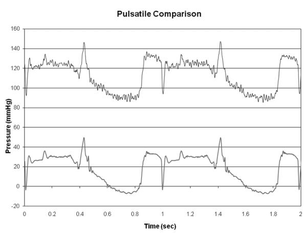
Pulsatile signal comparison of an Argon CDX pressure transducer (bottom) and the inlet pressure sensor (top). The inlet sensor is shown with a 100 mm-Hg offset.
Results
In Vitro Performance
Bench testing of the system has been performed including hydrodynamic performance, rotor motion studies, and hemolysis studies. Basic H-Q pump performance is presented in Figure 8 along with the CFD predicted H-Q predictions. These data were obtained with the rotor end clearance set at 1 mm which is the nominal setting. There is very good agreement between the CFD and experimental results the 8000 and 9000 RPM running conditions. At the lower rpm conditions the results diverge as the rpm decrease. The reason for this behavior is currently unknown and may be due to the rheology model or other assumptions associated with the rotor position constraints.
Figure 8.
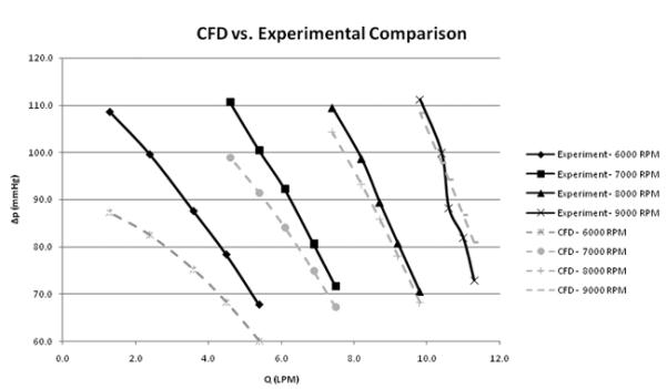
Experimental head rise vs. flow for three different rotor RPM values and CFD results for similar geometry and conditions. Data were taken with the rotor end gap of .040 in. Pressures were measured with wall pressure taps at the inlet and outlet of the pump in the same diameter tubes. Flows were measured with a calibrated rotometer. The working fluid was a 60/40 water-glycerol solution with a specific gravity of 1.1.
Figure 9 is a plot of the system power versus flow rate for several pressure rises. At 5 L/min and a pressure rise of 100 mmHg the CFD predicts a shaft power of 6W. This compares favorably with the system power from Figure 9 using the motor manufacture’s motor efficiency of 55% at that condition. Motor efficiency is reduced compared to a conventional motor configuration due to the increased motor air gap used in this Tesla pump design.
Figure 9.
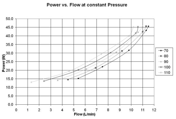
System power vs. Flow at constant pressure for a range of 70 to 110 mm Hg.
Although the rotor is theoretically stabilized in the center of the stator there are forces such as imbalance, asymmetry and fluid eddy forces that tend to destabilize the rotor. As the rotor deviates from the center of the stator a positive stabilizing force is imparted from the fluid. Thus the rotor path deviates from the stator centerline until equilibrium is reached. Motion was measured, using high speed video and custom software, as the radial offset distance of the rotor, Rc, from the center during operation. The offset distance oscillated with a period that varied with rotational speed. For speeds between 7000 to 10000 RPM, the average offset radius was 0.25 mm, and the amplitude of oscillations was between 0.75 and 1 mm. Rotor balancing techniques are being used in an effort to reduce the maximum amplitude.
After initial performance testing and comparison with the CFD, hemolysis testing was performed prior to an initial in vivo study. The objective of in vitro hemolysis testing was to evaluate the effect of LVAD operating conditions on hemolysis. The method utilized has been previously described.13-16 The pump was tested at rates of 6000, 7000 and 8000 RPM and differential (head rise) pressures of 70 or 90 mmHg with a pump rotor end gap of 1mm. A total of 6 experiments were conducted. During each experimental day, all three rate conditions were tested for approximately two hours each, while maintaining constant ΔP. All tests were repeated 3 times, while only changing the order of the rate condition tested.
The test was conducted at room temperature. Initially, the loop was filled with filtered and degassed Phosphate Buffered Saline (PBS) in order to perform degassing and wetting of the entire loop. Bovine blood, freshly obtained and collected into the standard 500 ml blood bag containing citrate phosphate dextrose adenine (CPDA1) anticoagulant solution, was also degassed in a vacuum chamber. Prior to degassing, 0.5 ml of heparin (1000 U/1ml) and 1 ml of antibiotic Tobramicin (40 mg/ml) were added in the blood bag in order to prevent coagulation and bacteria growth, respectively.
After displacing the PBS with blood, samples were taken every 30 minutes, and plasma free hemoglobin was measured according to the Shinowara15 method. The time rate of change of the plasma free hemoglobin concentrations, d(plHb)/dt, was calculated using a least-squares linear regression formula. The Normalized Index of Hemolysis (NIH), representing the hemoglobin released per unit volume of blood pumped (typically expressed in mg/dL), was used to quantify hemolysis. NIH was calculated by the following equation:
| (Eqn 2) |
where Hct is the mean hematocrit of the initial and final sample for the condition tested expressed in %, V is the volume of the loop in liters, and Q is the pump flow rate in liters/min. The inlet and outlet pressures were monitored while flow rate was measured using a Transonic ultrasound flow sensor (model 9XL, Transonic System Inc., Ithaca, NY) connected to model TS410 Transonic flow meter.
The results in Table 1 show acceptable levels of hemolysis with the exception of the condition at the lowest flow and high ΔP. The pump will not normally operate in this range for long periods of time.
Table 1.
Table Showing the Rate, Differential Pressure, Mean Flow Rate and Calculated Mean and Standard Deviation of NIH from the Hemolysis Tests Performed to Date
| Pump Rate (rpm) | ΔP (mmHg) | Q (L/min) | NIH (mg/dL) |
|---|---|---|---|
| 6000 | 70 | 3.9 ± 0.1 | 0.011 ± 0.002 |
| 7000 | 70 | 6.9 ± 0.2 | 0.010 ± 0.002 |
| 8000 | 70 | 9.7 ± 0.4 | 0.016 ± 0.004 |
| 6000 | 90 | 1.7 ± 0.3 | 0.040 ± 0.030 |
| 7000 | 90 | 4.7 ± 0.3 | 0.018 ± 0.008 |
| 8000 | 90 | 7.7 ± 0.6 | 0.018 ± 0.006 |
To date, five prototype pressure sensors have been manufactured. All sensors are able to withstand the maximum expected strain. The average sensitivity of the five prototypes is 0.52 ±0.24 μV/mmHg with one-half (0.50) volt excitation. Offset (zero pressure) drift for 2 units varied between 180 and −140 mmHg over a four week period. Span drift ranged from 18 to −21 μV (n = 5 units). Gain drift ranged from −7.4 to 4.9 μV (n = 5 units). Improved offset drift and temperature compensation are currently being investigated.
Transient response of the sensor is adequate and can be seen in Figure 7. Step response time for 90 mmHg step impulse averaged .02 seconds. Hysteresis ranged from −15 mmHg to 4.1 mmHg for holding the pressure at 75 mmHg for four hours and then releasing the pressure (n = 3 units). The cause of hysteresis is being investigated.
The pressure sensor currently used has been tested both in vitro and in vivo. The gain of the transducer is stable, but the baseline is prone to drift. The current semiconductor gage is bonded to the diaphragm using a thermally cured epoxy, which results in pre-stress of the gage. Even with post-cure bridge balancing, the different rate of thermal expansion for the composite materials can cause unpredictable baseline drift in the system.
Despite this problem, the current sensor may be used with high pass filtering, resulting in a pressure pulsatility signal. This signal is usable for control purposes since incipient ventricular collapse can be detected from pressure pulsatility as well as absolute pressure. An advantage of this approach is that pressure pulsatility does not require compensation for barometric pressure changes, and thus a sealed system could be used.
In Vivo Testing
To date, one five hour in vivo test was performed in a 100 kg calf. The device was placed extracorporeally as shown in Figure 3. The animal was heparinized and pump output was maintained at 4.5 to 5.5 L/min. The autopsy results revealed no emboli present in the kidneys or other organs. Disassembly of the device revealed one small clot in the rear back flow channel associated with a surface imperfection.
Conclusions
A passively suspended Tesla type pump with large flow channels was designed utilizing CFD. A prototype system was constructed and performance tested. The results compared favorably with the CFD results in the lower RPM range. Future CFD refinements will include additional degrees of freedom to model destabilizing forces such as separation/eddies, flow-related forces and accelerations, and changes in the flow velocities near the outlet, and will include a fluid-surface interaction model. Motion studies showed that rotor wobble exists but hemolysis studies have shown a satisfactory index of hemolysis over its operating range. The results of the first five hour acute in-vivo study were very encouraging with only one small thrombus associated with a surface imperfection. These studies support the concept that a passively supported Tesla pump has potential to become a lower cost device due to its passive support design, ease of fabrication and overall simple design that can be manufactured with rather wide tolerances.
Acknowledgments
Disclosure: Work was supported by NIH Grant #R01HL81119, Development of an Innovatively Suspended TESLA Pump LVAD
References
- 1.Tesla N, inventor. Turbine. 1,061,206 US Patent. 1913
- 2.Dorman FD, Murphy TE, Blackshear PL. An application of the Tesla viscous flow turbine to pumping blood: Mechanical devices to assist the failing heart. National Research Council, National Academy of Science. 1966:119–128. [Google Scholar]
- 3.Miller GE, Sidhu A, Fink R, Etter BD. Evaluation of a multiple disk centrifugal pump as an artificial ventricle. Artif Organs. 1993;17:590–592. doi: 10.1111/j.1525-1594.1993.tb00599.x. [DOI] [PubMed] [Google Scholar]
- 4.Miller GE, Fink R. Analysis of optimal design configurations for a multiple disk centrifugal blood pump. Artif Organs. 1999;23:559–565. doi: 10.1046/j.1525-1594.1999.06403.x. [DOI] [PubMed] [Google Scholar]
- 5.Miller GE, Etter BD, Dorsi JM. A multiple disk centrifugal pump as a blood flow device. IEEE Trans Biomed Eng. 1990;37:157–163. doi: 10.1109/10.46255. [DOI] [PubMed] [Google Scholar]
- 6.Izraelev V, inventor. Magnetically driven rotor for blood pump. 6,206,659 US Patent. 2001
- 7.Izraelev V, inventor. Blood pump having rotor with internal bore for fluid flow. 5,938,412 US Patent. 1997
- 8.Izraelev V, inventor. Pump assembly with bearing and seal-free reusable impeller for fragile and aggressive fluids. 6,547,539 US Patent. 2003
- 9.Rice W. Tesla turbomachinery. Paper presented at: IV International Tesla Symposium; Belgrade, Yugoslavia. 1991. [Google Scholar]
- 10.Rafferty E, Kietschka H, Wynyard M, Lackin J, Smith L. Artificial heart II- Application of nonpulsatile radially increasing pressure gradient pumping principle. Minn Med. 1968;52:191. [PubMed] [Google Scholar]
- 11.Fritz BP, Weiss W, Cysyk J, Izraelev V, Rosenberg G. Development of a pressure sensing device for a left ventricular assist device. ASAIO J. 2009;55:167. [Google Scholar]
- 12.Amin DV, Antaki JF, Litwak P, Thomas D, Wu ZJ, Watach M. Induction of ventricular collapse by an axial flow blood pump. ASAIO J. 1998;44:685–690. doi: 10.1097/00002480-199809000-00077. [DOI] [PubMed] [Google Scholar]
- 13.American Society for Testing and Materials ASTM 1841-97 Standard practice for assessment of hemolysis in continuous flow blood pumps. 1997. ASTM 1841-97.
- 14.Lukic B, Weiss WJ. The effect of pump rate and filling on hemolysis in a pulsatile left ventricular assist device. Paper presented at: IEEE 28th Annual Northeast Bioengineering Conference; Philadelphia, PA. 2002. [Google Scholar]
- 15.Shinowara GY. Spectrophotometric studies on blood serum and plasma; the physical determination of hemoglobin and bilirubin. Am J Clin Pathol. 1954;24:696–710. doi: 10.1093/ajcp/24.6.696. [DOI] [PubMed] [Google Scholar]
- 16.Naito K, Mizuguchi K, Nose Y. The need for standardizing the index of hemolysis. Artif Organs. 1994;18:7–10. doi: 10.1111/j.1525-1594.1994.tb03292.x. [DOI] [PubMed] [Google Scholar]


