Abstract
Degradable microparticles have broad utility as vehicles for drug delivery and form the basis of several FDA-approved therapies. Conventional emulsion-based methods of manufacturing produce particles with a wide range of diameters (and thus kinetics of release) in each batch. This paper describes the fabrication of monodisperse, drug-loaded microparticles from biodegradable polymers using the microfluidic flow-focusing (FF) devices and the drug delivery properties of those particles. Particles were engineered with defined sizes, ranging from 10 μm to 50 μm. These particles were nearly monodisperse (polydispersity index = 3.9 %). We incorporated a model amphiphilic drug (bupivacaine) within the biodegradable matrix of the particles. Kinetic analysis showed that the release of drug from these monodisperse particles was slower than that from conventional methods of the same average size but a broader distribution of sizes and, most importantly, exhibited a significantly lower initial burst than that observed with conventional particles. The difference in the initial kinetics of drug release was attributed to the uniform distribution of drug inside the particles generated using the microfluidic methods. These results demonstrated the utility of microfluidic FF for the generation of homogenous systems of particles for the delivery of drugs.
Introduction
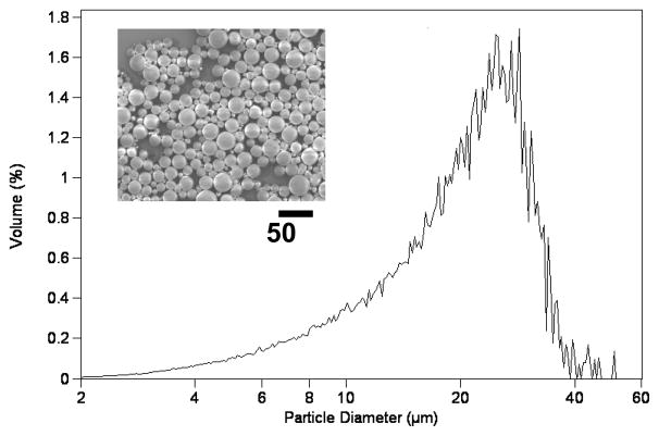
In drug formulation, control of the spatial and temporal kinetics of drug release at the site of action is key to achieving an optimal pharmokinetic effect.[1] Microspheres made from biodegradable polymers (e.g. poly (lactic-co-glycolic acid) have been widely used as matrices for drug delivery to achieve such controlled drug release.[2–4] Several parameters influence the characteristics of drug release from the PLGA matrix, including the rate of degradation of PLGA, the internal morphology of the particle, the solubility of the entrapped drug, and the percentage of drug loading in the particle.[5–8] Typical procedures use sonication or mechanical homogenization to generate drug-loaded PLGA microparticles, in which the continuous (aqueous) phase contains a polymeric stabilizer and the dispersed (organic) phase contains the drug and the PLGA. Figure 1 shows the characteristic broad distribution of sizes for microparticles that we prepared using a conventional method for emulsification, even after filtration through a 60 μm sieve. The polydispersity and batch-to-batch variation in both the size and morphology of microparticles resulting from the conventional method of emulsification may produce undesirable variation in the rate of microparticle degradation, the stability of the drug, and the kinetics of drug release.[6] Furthermore, large particles on the upper end of the particle size distribution can promote the formation of aggregates and/or clog a needle upon in vivo injection. Several methods to generate droplets, including acoustic excitation,[9, 10] spinning oil film,[11] and replica molding,[12, 13] have been developed to control the size of the particles and thus to control the profiles of drug release. In this manuscript, we describe the fabrication of monodisperse drug-loaded polymer particles of tunable sizes using the microfluidic method and discuss the influence of particle sizes and fabrication procedures on the drug release kinetics. Microfluidic droplet generators intrinsically produce monodisperse droplets suitable for our application and offer easy control over the size of the particles that are generated.
Figure 1.
SEM and size distribution of PLGA microparticles prepared using a conventional emulsion method followed by filtering through a 60 μm sieve.
Microfluidic technologies offer low-cost and easy-to-use platforms for controlling fluid flow. Emulsions generated in microfluidic systems have been used in areas that include bioanalysis, organic synthesis, and fluidic optics.[14–17] There are two broad classes of devices for generating emulsions in microfluidic platforms: T-junctions[18–20] and flow-focusing nozzles[21–23]. Both methods make it possible to generate monodisperse particles, and both offer flexibility in the size of emulsions that are generated. Flow-focusing (FF) devices have been commonly used to make monodisperse polymer particles, both spherical and non-spherical. The use of FF devices to fabricate photocurable polymeric particles,[24–26] ion-crosslinkable thermosensitive gels[27, 28] polymer-encapsulated cells,[29, 30] and other particles[31, 32] has been demonstrated. In most previous studies, however, there has been little systematic effort to characterize the drug release kinetics from the particles generated by microfluidic devices. Specifically, no previous study (to our knowledge) has addressed the fundamental differences between the drug delivery kinetics of microparticles fabricated via traditional methods to generate emulsions and those produced via microfluidics in terms of their respective morphologies.
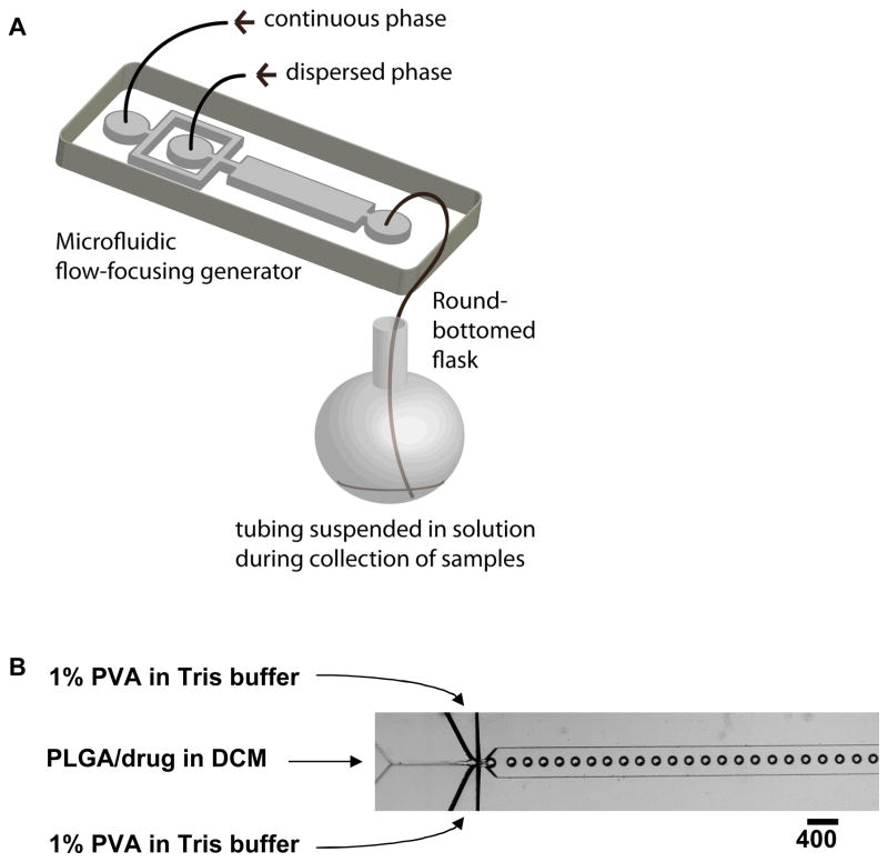
Our objective in this research was to fabricate monodisperse, biodegradable drug-loaded microparticles. The procedure to fabricate polymer microparticles combined the generation of monodispserse droplets of solvent containing PLGA and drug (using a flow-focusing generator) with subsequent removal of solvent to form the PLGA-drug particles (Figure 2). We conducted systematic studies of the size-dependent profiles of drug release of the monodisperse particles, and compared their kinetics of release with particles of the same average size made using a conventional method for emulsification. We believe that the flow focusing approach described here may have utility in the controlled production of microspheres for pharmaceutical application.
Figure 2.
(A) Schematic illustration of the procedure to fabricate monodisperse polymer microparticles, and (B) optical microscopic image showing the orifice of the flow-focusing region generating droplets of dichloromethane (DCM) in water.
Experimental Design
We used a flow-focusing device, rather than a T-junction device, to generate polymeric particles in this research. In the T-junction geometry, the dispersed phase stays in contact with one of the side walls of the PDMS device [18–20] The surface properties of PDMS can change upon exposure to organic solvents; in this case, we noticed that the hydrophilic (i.e. plasma oxidized) PDMS rapidly becomes hydrophobic upon exposure to dichloromethane (CH2Cl2). The dichloromethane phase containing PLGA eventually wetted the sidewall of the device. This wetting prevented the formation of discrete droplets (and thus particles).
In the flow-focusing geometry, the dispersed phase (i.e. dichloromethane) is surrounded by the continuous phase (i.e. water) as long as the surface of PDMS stays hydrophilic. To avoid bringing the organic phase into contact with the hydrophilic, plasma-oxidized PDMS walls of the device, we filled the device with the aqueous phase before introducing the organic (dispersed) phase[33]. We introduced the dispersed phase at low rates of flow in order to avoid co-laminar flows and hydrophobic wetting of the PDMS device. After exposing the PDMS surface to dichloromethane, the surface of PDMS became hydrophobic. The height of the channel must be larger than the diameter of the droplets to prevent the formation of disc-shape droplets and the eventual wetting of the walls of the channel. With the combination of fluids that we used in this experiments, the flow-focusing system can generate monodisperse particles for at least five hours (the duration of our experiment) under the conditions of flow that we used (details in the experimental section) with no noticeable changes in surface properties of the device. We speculate that an axisymmetric flow-focusing system may operate even more stably, as the dispersed phase is surrounded symmetrically by a continuous phase.[34, 35]
Results and Discussion
Fabrication of PLGA Particles
The experimental section gives the complete procedure used to fabricate drug-loaded PLGA particles by combining flow-focusing microfluidics with evaporation of solvent. Briefly, we introduced an aqueous solution of 1% poly(vinyl alcohol) (PVA) into the two side channels of a FF device as a continuous phase, and a solution of PLGA in dichloromethane (CH2Cl2) into the central channel as a dispersed phase. The stream of CH2Cl2 broke up at the junction of three inlets to generate droplets of CH2Cl2/PLGA/drug of uniform size[22, 23]. PVA dissolved in the continuous aqueous phase acted as a surfactant, and adsorbed to the surface of the droplets in the downstream channel to prevent coalescence of the droplets in the collecting container. Droplets were collected in a 100-mL round-bottomed flask containing 10 mL of an aqueous solution of Tris buffer (pH = 8.5). The pre-loaded buffer in the collecting flask diluted the particles, and minimized aggregation; the high pH of the buffer minimized leaching of bupivacaine (which is only minimally soluble in water at pH > 8.1) from the particles. The system was run for 30 minutes (representing 1 mL of the CH2Cl2 solution), after which the collection flask was immediately mounted on a rotary evaporator. The dichloromethane was removed by evaporation under reduced pressure (70 mTorr) over a period of 3 minutes, although no visible bubbling occurred after 10 seconds. The particles were then centrifuged, washed three times with water, and lyophilized to generate dried drug-loaded microspheres. We obtained 80 mg of particles per hour per microfluidic FF device.
Particle Size Distributions
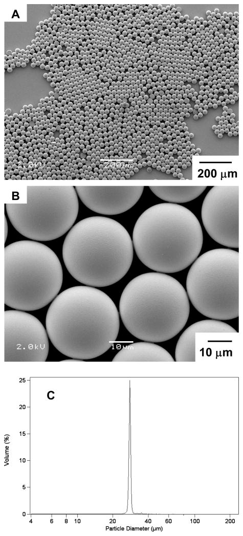
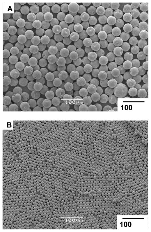
Figure 3A and B show the size and morphology of the microparticles obtained via the microfluidics technique. Figure 3C shows the narrow distribution of sizes (~28 μm in diameter) for the microparticles, as measured using a Beckman Coulter Multisizer (polydispersity index = 3.9 %, defined as the ratio between the standard deviation and the mean diameter of particles multiplied by 100). The size of the particles could be tuned by changing the rates of flows of the two phases, ranging between 4.0 – 20.0 mL/hr for the continuous phase and 0.5 – 2.0 mL/hr for the dispersed phase. Above a certain threshold (e.g., a rate of flow of dispersed phase above 1.0 mL/hr when the rate of flow of the continuous phase was held at 4.0 mL/hr), the system formed co-laminar flows and did not generate droplets.[22, 23] Figure 4 shows microparticles with average diameters of 41 μm and 11 μm fabricated with the same microfluidic device using different rates of flow.
Figure 3.
(A, B) SEM images of monodisperse PLGA microparticles with diameter ~28 μm. (C) Size distribution of the microparticles measured using a coulter counter.
Figure 4.
SEM images of microparticles prepared via microfluidics with different sizes: (A) 42 μm, (B) 12 μm.
In vitro Drug Release Studies
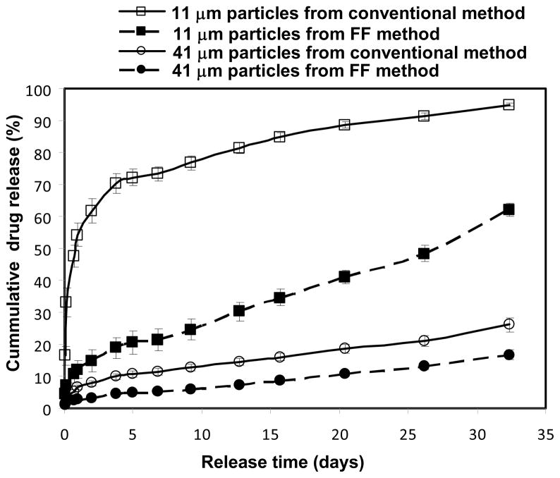
We incorporated bupivacaine (a local anesthetic) into the microparticles by dissolving the free base form of the drug into a solution of CH2Cl2 and PLGA. We fabricated monodisperse microparticles with two different diameters (11 μm and 41 μm) and studied the kinetics of release of bupivacaine from each particle. For comparison, microparticles with similar average size were also prepared using the conventional single-emulsion technique[8] and assayed for release of drug. Figure 5 shows the kinetic profiles of in vitro release of drug from the drug-loaded PLGA microparticles. In general, smaller particles released drug more rapidly than larger particles; this difference is expected according to the larger surface area-to-volume ratio of the smaller particles. There were two significant differences between the kinetics of drug release of monodisperse, microfluidic particles and polydisperse, conventional particles with similar average sizes but a much broader distribution of sizes. First, monodisperse particles prepared using microfluidics released drug more slowly than conventional polydisperse particles of similar average size. Second, the initial burst release of drug observed with monodisperse, microfluidic particles is significantly smaller than that observed with the corresponding conventional, polydisperse particles.
Figure 5.
Drug release profiles from monodisperse microparticles prepared with microfluidic devices and polydisperse microparticles prepared using the conventional single emulsion technique.
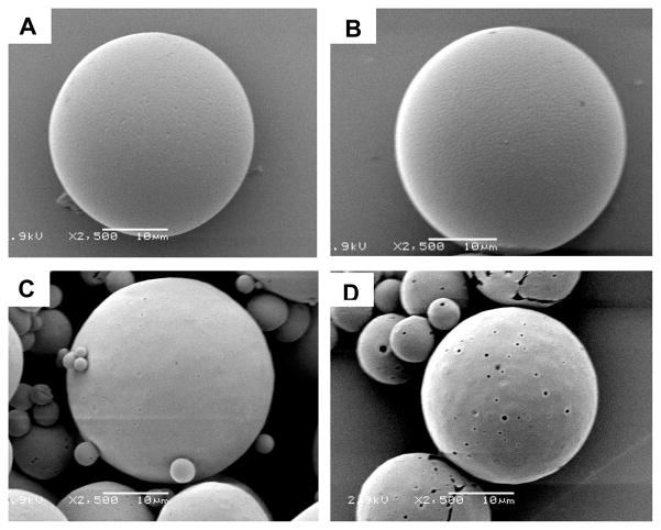
To understand the origin of these differences in kinetics, we investigated the morphologies of microparticles prepared using the two methods. Since bupivacaine is soluble in aqueous acidic solution, treating the microparticles with an acidic solution leaches the drug out of the particles to reveal the surface distribution of the drug. Both conventional and microfluidic particles contained approximately the same total percentage of drug (~18 w/w% for the conventional particles and ~20 w/w% for the microfluidic particles); we believe that any differences in surface morphology should be related to the distribution of drug within the particles, rather than the loading of the drug. Figure 6 shows the surface morphology of the two particles before and after a one-hour treatment in a 1 M aqueous solution of HCl. No obvious change occurred on the surface of the microparticles fabricated using the microfluidic device (Figure 6B) while several large pores formed on the surface of the microparticles formed using the conventional method for emulsification (Figure 6D). These results suggest that less drug was adsorbed or trapped near the surface of the microparticles fabricated using the microfluidic device than those prepared using the conventional emulsification approach. We hypothesize that mixing in microfluidic device is more homogeneous, leading to the more uniform drug distribution in the microparticles. Particles prepared using the conventional emulsion method may have drug-rich domains at or near the particle surface. The larger amount of the drug adsorbed near the surface may account for the more rapid rate of drug release from particles fabricated using the conventional method compared to particles fabricated using the microfluidic method. In addition, the high number of small particles present in the polydisperse particles may also be an important contributor to both the initial burst release and faster overall kinetics observed in particles prepared using the conventional method for emulsification.
Figure 6.
Surface topology of the microparticles before (A, C) and after (B, D) treatment with 1 M HCl for 1 hr. (A, B) particles fabricated using microfluidic devices. (C,D) particles prepared from conventional single emulsion method.
Conclusion
We successfully fabricated monodisperse biodegradable drug-loaded microparticles by combining the formation of droplets in a microfluidic flow-focusing generator with rapid evaporation of solvent from the droplets. The size of the particles can be tuned by controlling the conditions of flow within a given microfluidic device. One potential application of this ability to control particle size is the independent synthesis of two or more sets of monodisperse microparticles, followed by their mixing designed to achieve designed dosing patterns based on a single-injection treatment. The same strategy could be applied to control the rates of release of two different drugs independently. Microfluidics-based, monodisperse microparticles exhibit significantly reduced burst release and slower overall rates of release than do conventional, polydisperse microparticles of similar average sizes and overall loading of drug, which may allow for delivery with less variable release, as well as release over a longer period of time than particles prepared via conventional methods to generate emulsions.
The ability to produce monodisperse particles for drug delivery also has several practical advantages. The reduced shear stresses used to prepare particles in a microfluidics device compared to a conventional emulsion may assist in maintaining the bioactivity of shear-sensitive biomolecular drugs (i.e. protein therapeutics) released from biodegradable microparticles. Given that the conventional emulsion approach typically produces aggregates which must be removed by filtration, particles prepared using the microfluidic method can be produced with higher yields than are typical via the conventional approach – a significant advantage, particularly for expensive drugs. Furthermore, the use of monodisperse particles would enable the injection of larger (i.e. slower releasing) particles since larger particles on the upper tail of the particle size distribution (which increase the probability of clogging of needles) are not present.
The productivity of a single FF device is limited (here, to ~ 50 – 300 mg/hr of particles). These FF devices are, however, trivial to produce in quantities and to operate in parallel.[37] Thus, a thousand FF devices in parallel should be able to generate 50 – 300 g/hr of particles, or 1 – 6 kg/day. This level of productivity is probably less expensively achieved using a FF system than using alternative technologies for micromolding.[12, 13] Modification of this procedure based on previously described methods also enables the fabrication of particles with morphologies other than spheres (e.g. monodisperse rods and discs).[25]
Experimental Section
Fabrication of Microfluidic Devices
We fabricated the microfluidic channels using soft lithography.[33, 38] The height of each device ranged from 100 μm to 120 μm. We sealed the plasma-oxidized polydimethylsiloxane (PDMS) mold against an oxidized glass slide (Corning); it was necessary to plasma-oxidize the surfaces of both the PDMS and the glass before bringing them into contact to make covalent bonds.[33] In order to avoid the wetting of the dispersed phase to the inner surface of the device, we filled the channel with aqueous solution of PVA (the continuous phase used for the subsequent experiments) immediately after sealing the PDMS mold to the glass slide.[33]
Fabrication of PLGA Particles using Microfluidic Devices
The continuous phase was an aqueous solution (Millipore, deionized) of Tris buffer (pH = 8.5, 0.2 M, Sigma) containing polyvinyl alcohol (PVA; 1.0 % w/w, MW = 6000, Polysciences, Inc.) as a surfactant. The dispersed phase was dichloromethane containing poly(lactic-co-glycolic) acid (PLGA; 40 mg/mL, Mw=50,000–75,000, lactide: glycolide = 85: 15, Sigma) and 25% w/w of bupivacaine in its free base form. Bupivacaine hydrochloride (St. Louis, Sigma) was converted into the free base by alkaline precipitation and filtration.[39] Digitally controlled syringe pumps (Harvard Apparatus, model PHD2000) delivered both liquid phases to the microfluidic device at constant rates of flows. The rate of flow of the dispersed phase (Qd) was 0.5 – 2.0 mL/hr while the rate of flow of the continuous phase (Qc) was 4.0 – 20.0 mL/hr. Three different sets of flow rates, [Qd, Qc] = [1.0, 20.0], [1.0, 10.0], and [1.0, 4.0], were used to obtain particles with diameters of 12 μm, 28 μm, 42 μm, respectively. (The descriptor, [Qd (mL/hr), Qc (mL/hr)], denotes the rates of flow of the dispersed phase and the continuous phase.) Teflon tubing (WEICO) connected the syringes with the inlets of the device as well as the outlet of the device with a round-bottomed flask (500 mL) containing 10 mL of Tris buffer. The end of the tubing was suspended in the buffer solution in the flask. The system was run for 30 minutes, after which the flask was immediately mounted on a rotary evaporator. The CH2Cl2 solvent within the droplets was removed by evaporation under reduced pressure (70 mTorr) at room temperature for 3 minutes. After removal of CH2Cl2, solidified microparticles of PLGA were collected in a 50-mL conical tube (Becton, Dickinson and Company), centrifuged (1500 rpm, 5 min), and rinsed with deionized water (30 mL) three times to remove excess PVA. The particle suspension was then quick-frozen in liquid nitrogen and lyophilized under reduced pressure to remove the continuous aqueous phase.
Imaging and Recording
An upright microscope (Leica DMRX) and a set of still (Nikon Digital Camera DXM 1200) and fast-video (Phantom V7) cameras were used to visualize and record movies of the system. The specimens were imaged with a JEOL JSM 6060 scanning microscope (JEOL USA, Peabody, MA) using 2.5–5 kV accelerating voltage at a 10 mm working distance.
Fabrication of PLGA Particles using Single Emulsion Method
Microspheres loaded with 20% (w/w) bupivacaine were prepared using a single emulsion method.[40, 41] A solution of bupivacaine and PLGA dissolved in dichloromethane was added quickly to a solution of 50 mL 0.5% polyvinyl alcohol in 100 mM Trizma buffer (pH 8.5), and homogenized for 60 seconds at 3000 rpm (Silverson L4R, Silverson Machines Ltd., Cheshire, England). The resulting suspension was quickly decanted into 100 mL of 100 mM Trisma pH 8.5 buffer and stirred for 30 seconds prior to rotary evaporation (Büchi Rotavap, Büchi, Switzerland) for 3 minutes, in parallel with the microfluidics particles. Microspheres with diameters between 20 μm and 106 μm were isolated by sieving (Newark Wire Co., Newark, NJ) and resuspended in 50 mL of water. The suspension was washed three times by centrifugation at 3000 rpm for 5 minutes, immediately quick-frozen in liquid nitrogen, and lyophilized to dryness, again in parallel with the microfluidics particles.
Measurement of the Bupivacaine Content of Microparticles
The bupivacaine content of all microspheres was determined by dissolving 2 mg of microspheres in 1 mL of acetonitrile and comparing the resulting UV absorbance at 272 nm to a standard curve of known concentrations of bupivacaine in acetonitrile. The presence of PLGA did not interfere with the assay, as confirmed by assaying PLGA-only microparticles prepared without bupivacaine using the same method.
In vitro Release of Bupivacaine from Microparticles
We used the samples and separation method to study the release of drug from microparticles.[8] Briefly, 1 mg of bupivacaine-loaded monodisperse or polydisperse PLGA microspheres of each size were suspended in 1 mL of 0.9 % (w/v) NaCl solution in a 1.5-mL centrifuge tube. The centrifuge tube was incubated at 37°C on a tilt-table (Ames Aliquot Mixer, Miles). At predetermined intervals, the tube was centrifuged at 12000 rpm for 5 min using an Eppendorf 5424 microcentrifuge. The supernatant was collected and replaced with an equal volume of fresh 0.9 % (w/v) aqueous NaCl solution. The concentration of bupivacaine in the collected supernatant was quantified using HPLC analysis. After a release period of 30 days, the suspension of particles depleted in bupivacaine was completely dissolved in acetonitrile overnight. The percent of drug release at each time point was calculated by normalizing the data collected at each time with the cumulative total amount of drug inside the particles. The kinetics of release reported for each size of the particle size were obtained from the average of triplicate experiments.
Acknowledgments
This research was supported by in part Shire Pharmaceutics Inc. Q. X. is grateful to the support from MIT-Harvard Center of Cancer Nanotechnology Excellence (CCNE) for his postdoctoral fellowship. M. H. is grateful to the financial support from the US Department of Energy under award DE-FG02-OOER45852; this grant also supported the development of much of the underlying technology of FF systems. Shared facilities at Harvard University funded by NSF under MRSEC award DMR-0213805 were utilized for some of the work. T.D is grateful to the Agency for Science, Technology and Research of Singapore for the A*STAR graduate fellowship. T.H. is grateful to the Natural Sciences and Engineering Research Council of Canada for funding his postdoctoral fellowship.
References
- 1.Kost J, Langer R. Adv Drug Deliv Rev. 2001;46:125. doi: 10.1016/s0169-409x(00)00136-8. [DOI] [PubMed] [Google Scholar]
- 2.Langer R, Peppas N. J Macromol Sci, Rev Macromol Chem Phys. 1983;C23:61. [Google Scholar]
- 3.Langer R. Science. 1990;249:1527. doi: 10.1126/science.2218494. [DOI] [PubMed] [Google Scholar]
- 4.Uhrich KE, Cannizzaro SM, Langer RS, Shakesheff KM. Chem Rev. 1999;99:3181. doi: 10.1021/cr940351u. [DOI] [PubMed] [Google Scholar]
- 5.Spenlehauer G, Vert M, Benoit JP, Chabot F, Veillard M. J Controlled Release. 1988;7:217. [Google Scholar]
- 6.Sansdrap P, Moes AJ. Int J Pharm. 1993;98:157. [Google Scholar]
- 7.Izumikawa S, Yoshioka S, Aso Y, Takeda Y. J Controlled Release. 1991;15:133. [Google Scholar]
- 8.D’Souza SS, DeLuca PP. Pharm Res. 2006;23:460. doi: 10.1007/s11095-005-9397-8. [DOI] [PubMed] [Google Scholar]
- 9.Berkland C, King M, Cox A, Kim K, Pack DW. J Controlled Release. 2002;82:137. doi: 10.1016/s0168-3659(02)00136-0. [DOI] [PMC free article] [PubMed] [Google Scholar]
- 10.Berkland C, Kim K, Pack DW. J Controlled Release. 2001;73:59. doi: 10.1016/s0168-3659(01)00289-9. [DOI] [PubMed] [Google Scholar]
- 11.Leach WT, Simpson DT, VTN, Yu Z, Lim KT, Park EJ, Williams ROI, Johnston KP. AAPS PharmSciTech. 2005;6:E605. doi: 10.1208/pt060475. [DOI] [PMC free article] [PubMed] [Google Scholar]
- 12.Rolland JP, Maynor BW, Euliss LE, Exner AE, Denison GM, DeSimone JM. J Am Chem Soc. 2005;127:10096. doi: 10.1021/ja051977c. [DOI] [PubMed] [Google Scholar]
- 13.Gratton SEA, Pohlhaus PD, Lee J, Guo J, Cho MJ, DeSimone JM. J Controlled Release. 2007;121:10. doi: 10.1016/j.jconrel.2007.05.027. [DOI] [PMC free article] [PubMed] [Google Scholar]
- 14.Zheng B, Roach LS, Ismagilov RF. J Am Chem Soc. 2003;125:11170. doi: 10.1021/ja037166v. [DOI] [PubMed] [Google Scholar]
- 15.Hatakeyama T, Chen DLL, Ismagilov RF. J Am Chem Soc. 2006;128:2518. doi: 10.1021/ja057720w. [DOI] [PMC free article] [PubMed] [Google Scholar]
- 16.Hung LH, Choi KM, Tseng WY, Tan YC, Shea KJ, Lee AP. Lab Chip. 2006;6:174. doi: 10.1039/b513908b. [DOI] [PubMed] [Google Scholar]
- 17.Hashimoto M, Mayers B, Garstecki P, Whitesides GM. Small. 2006;2:1292. doi: 10.1002/smll.200600211. [DOI] [PubMed] [Google Scholar]
- 18.Thorsen T, Roberts RW, Arnold FH, Quake SR. Phys Rev Lett. 2001;86:4163. doi: 10.1103/PhysRevLett.86.4163. [DOI] [PubMed] [Google Scholar]
- 19.Nisisako T, Torii T, Higuchi T. Lab Chip. 2002;2:24. doi: 10.1039/b108740c. [DOI] [PubMed] [Google Scholar]
- 20.Garstecki P, Fuerstman MJ, Stone HA, Whitesides GM. Lab Chip. 2006;6:437. doi: 10.1039/b510841a. [DOI] [PubMed] [Google Scholar]
- 21.Gañán-Calvo AM, Gordillo JM. Phys Rev Lett. 2001;87:274501. doi: 10.1103/PhysRevLett.87.274501. [DOI] [PubMed] [Google Scholar]
- 22.Anna SL, Bontoux N, Stone HA. Appl Phys Lett. 2003;82:364. [Google Scholar]
- 23.Garstecki P, Gitlin I, DiLuzio W, Whitesides GM, Kumacheva E, Stone HA. Appl Phys Lett. 2004;85:2649. [Google Scholar]
- 24.Zhang H, Tumarkin E, Peerani R, Nie Z, Sullan RMA, Walker GC, Kumacheva E. J Am Chem Soc. 2006;128:12205. doi: 10.1021/ja0635682. [DOI] [PubMed] [Google Scholar]
- 25.Xu S, Nie Z, Seo M, Lewis P, Kumacheva E, Stone HA, Garstecki P, Weibel DB, Gitlin I, Whitesides GM. Angew Chem, Int Ed. 2005;44:724. doi: 10.1002/anie.200462226. [DOI] [PubMed] [Google Scholar]
- 26.Dendukuri D, Pregibon DC, Collins J, Hatton TA, Doyle PS. Nat Mater. 2006;5:365. doi: 10.1038/nmat1617. [DOI] [PubMed] [Google Scholar]
- 27.Kim JW, Utada AS, Fernandez-Nieves A, Hu N, Hu Z, Weitz DA. Angew Chem, Int Ed. 2007;46:1819. doi: 10.1002/anie.200604206. [DOI] [PubMed] [Google Scholar]
- 28.De Geest BG, Urbanski JP, Thorsen T, Demeester J, De Smedt SC. Langmuir. 2005;21:10275. doi: 10.1021/la051527y. [DOI] [PubMed] [Google Scholar]
- 29.Tan WH, Takeuchi S. Adv Mater. 2007;19:2696. [Google Scholar]
- 30.Clausell-Tormos J, Lieber D, Baret JC, El-Harrak A, Miller OJ, Frenz L, Blouwolff J, Humphry KJ, Koester S, Duan H, Holtze C, Weitz DA, Griffiths AD, Merten CA. Chem Biol. 2008;15:427. doi: 10.1016/j.chembiol.2008.04.004. [DOI] [PubMed] [Google Scholar]
- 31.Chang JY, Yang CH, Huang KS. Nanotechnology. 2007;18:305305/1. [Google Scholar]
- 32.Karnik R, Gu F, Basto P, Cannizzaro C, Dean L, Kyei-Manu W, Langer R, Farokhzad OC. Nano Lett. 2008;8:2906. doi: 10.1021/nl801736q. [DOI] [PubMed] [Google Scholar]
- 33.McDonald JC, Duffy DC, Anderson JR, Chiu DT, Wu HK, Schueller OJA, Whitesides GM. Electrophoresis. 2000;21:27. doi: 10.1002/(SICI)1522-2683(20000101)21:1<27::AID-ELPS27>3.0.CO;2-C. [DOI] [PubMed] [Google Scholar]
- 34.Utada AS, Lorenceau E, Link DR, Kaplan PD, Stone HA, Weitz DA. Science. 2005;308:537. doi: 10.1126/science.1109164. [DOI] [PubMed] [Google Scholar]
- 35.Takeuchi S, Garstecki P, Weibel DB, Whitesides GM. Adv Mater. 2005;17:1067. [Google Scholar]
- 36.Kohane DS, Smith SE, Louis DN, Colombo G, Ghoroghchian P, Hunfeld NGM, Berde CB, Langer R. Pain. 2003;104:415. doi: 10.1016/s0304-3959(03)00049-6. [DOI] [PubMed] [Google Scholar]
- 37.Nisisako T, Torii T. Lab Chip. 2008;8:287. doi: 10.1039/b713141k. [DOI] [PubMed] [Google Scholar]
- 38.Xia YN, Whitesides GM. Annu Rev Mater Sci. 1998;28:153. [Google Scholar]
- 39.Kohane DS, Lipp M, Kinney RC, Lotan N, Langer R. Pharm Res. 2000;17:1243. doi: 10.1023/a:1026470831256. [DOI] [PubMed] [Google Scholar]
- 40.Curley J, Castillo J, Hotz J, Uezono M, Hernandez S, Lim JO, Tigner J, Chasin M, Langer R, Berde C. Anesthesiology. 1996;84:1401. doi: 10.1097/00000542-199606000-00017. [DOI] [PubMed] [Google Scholar]
- 41.Watts PJ, Davies MC, Melia CD. Crit Rev Ther Drug Carr Syst. 1990;7:235. [PubMed] [Google Scholar]


