Abstract
The development of materials to support bone regeneration requires flexible fabrication technologies able to tailor chemistry and architecture for specific applications. In this work, we describe the preparation of ceramic-based inks for robotic-assisted deposition (robocasting) using Pluronic® F-127 solutions. This approach allows the preparation of pseudoplastic inks with solid contents ranging between 30–50 vol% enabling them to flow through a narrow printing nozzle while supporting the weight of the printed structure. Ink formulation does not require the manipulation of the pH or the use of highly volatile organic components. Therefore, the approach can be used to prepare materials with a wide range of compositions, and here we use it to build hydroxyapatite (HA), β-tricalcium phosphate (β-TCP), and biphasic (HA/β-TCP) structures. The flow of the inks is controlled by the Pluronic® content and the particle-size distribution of the ceramic powders. The use of wide size distributions favors flow through the narrow printing nozzles, and we have been able to use printing nozzles as narrow as 100 μm in diameter, applying relatively low printing pressures. The microporosity of the printed lines increases with increasing Pluronic® contents and lower sintering temperatures. Microporosity can play a key role in determining the biological response to the materials, but it also affects the strength of the structure.
Keywords: calcium phosphates, scaffolds, strength, sintering, computer-assisted fabrication
1. Introduction
Calcium phosphate ceramics have been successfully used in bone replacement for more than 30 years [1]. These synthetic materials are an alternative to autografts (still considered the gold standard by many surgeons [2]), as they eliminate painful side effects associated with bone harvesting [3] and the risks of employing bone allografts obtained from cadavers [4]. The most widely employed calcium phosphate materials are hydroxyapatite (HA, Ca10(PO4)6(OH)2) and tricalcium phosphate in both of its polymorphs (α and β-TCP, Ca3(PO4)2). HA and β-TCP as well as their mixtures are osteoconductive [5, 6] and can be used as fillers to coat the surface of metallic implants and in drug delivery devices [7, 8]. However, their future seems to be closely tied to the field of tissue regeneration, where these materials should play a major role in the fabrication of scaffolds for bone engineering [9]. These scaffolds need an interconnected network of macro- and microporosity for cell seeding and new bone formation [10]. An ideal three-dimensional (3D) scaffold should substitute, at least temporally, for the tissue while providing a substrate for cell attachment and proliferation and resorbing gradually as new tissue grows in vitro or in vivo [11]. Because β-TCP is more water soluble than HA[12], its in vivo behavior is very different; the higher the β-TCP/HA ratio, the more soluble a biphasic calcium phosphate material (BCP) will be β-TCP dissolves preferentially from the matrix, releasing calcium and phosphate ions to the media, enhancing the in vivo activity of the material and decreasing the resorption time [5, 13]. However, in vitro testing indicates that enhanced dissolution can be detrimental to the mechanical strength of the calcium phosphates materials in vivo [14]. Several studies suggest that an ideal calcium phosphate scaffold should be a mixture of both phases[15, 16].
Diverse techniques such as the use of replica templates (starting from polymeric sponges [17] or coral structures [18]), emulsion [19], the use of porogens [20], and freeze casting [21] have been used to build porous ceramic scaffolds for tissue engineering. However, most of them offer only a very limited control of the porosity and are not suited to the fabrication of materials with complex shapes. New solid-free-form fabrication techniques developed during the past 20 years allow the fabrication of ceramic materials with very complex architectures by following a computer design [22]. These architectures can be optimized to promote bone regeneration and enhance the mechanical response of the scaffolds [23]. Among these, robocasting, a technique that combines an extrusion process with a computer-guided positioning system, can be used to build 3D structures layer by layer, by extruding a continuous filament. Robocasting inks have to flow under stress and recover enough stiffness such that, when the stress is released, they can bear both the filament weight and the weight of successive layers. Robocasting permits printing with outstanding spatial resolution and has been used to print ceramic grids with line and gap diameters varying from hundreds of microns to submicron levels [24].
In the initial formulation of robocasting inks by Cesarano[25], drying of the filaments as soon as they were extruded provided enough rigidity to support the printed structure. Marchi et al. [26] prepared alumina inks where coagulation was achieved through the in situ gellification of aluminum hydroxide gels by raising the pH of alumina slurries with dissolved aluminum chloride (AlCl3). Smay et al. [27] developed viscoelastic inks by dispersing the ceramic particles in water and using polyethyleneimine (PEI) as a coagulant agent. The interaction between the ammonium polyacrylate-based dispersant adsorbed on the particle surfaces and the ionized PEI creates a network that confers viscoelastic behavior to the ink. These inks have a very low organic content and can be printed inside a non-wetting oil bath, avoiding the appearance of tensions derived from uneven drying [28–30]. However, tuning the viscoelastic behavior requires a precise adjustment of the amount of dispersant and PEI as well as careful control of the pH. The latter can be a problem, for example, when printing various calcium phosphates whose solubility is very dependent on the pH. Yang et al. [31] have also printed filament structures employing a system based on isopropyl alcohol with a combination of polyvinyl butyral (PVB) and polyethylene glycol as binders. Because these inks are alcohol based, the printing process takes place inside a controlled atmosphere chamber to avoid a fast drying, which might compromise the integrity of the printed structures. In addition, these inks have typically larger organic contents than the water-based ones, which may limit densification after sintering.
The main objective of this work is to design a flexible ink formulation approach to print a wide range of calcium phosphates. This would enable the fabrication of rigid scaffolds with composition and microstructure optimized for specific applications. Water-based inks are preferable because their organic content is much lower and they can be used in combination with the printing-in-oil technique developed by Smay et al. [27] to avoid problems associated with simultaneous printing and drying. Several studies have suggested that roughness and microporosity of the scaffold walls can have an important effect on the scaffold’s biological performance [32–34]. Ink formulations that allow an easy control of these parameters will provide an advantage in the fabrication of custom-designed scaffolds. The inks developed in this work are based on the dispersion of ceramic particles in water-based solutions of Pluronic® F-127 (BASF registered brand), a synthetic copolymer of ethylene oxide and propylene oxide represented by the following chemical formula: HO(C2H4O)a(C3H6O)b(C2H4O)a. These water-based inks can be used to print hydrophilic ceramics with a wide range of compositions without manipulating the interparticle forces (e.g., controlling the pH of the solution). Here we demonstrate how this approach can be used to print porous calcium phosphate structures (HA, β-TCP, and BCP) with a large spatial resolution while controlling the microporosity and roughness of the printed lines. The influence of the ink formulation on the printing process, the microstructure, and mechanical properties of the scaffolds are analyzed in detail.
2. Materials and Methods
2.1. Powder Preparation and Materials Characterization
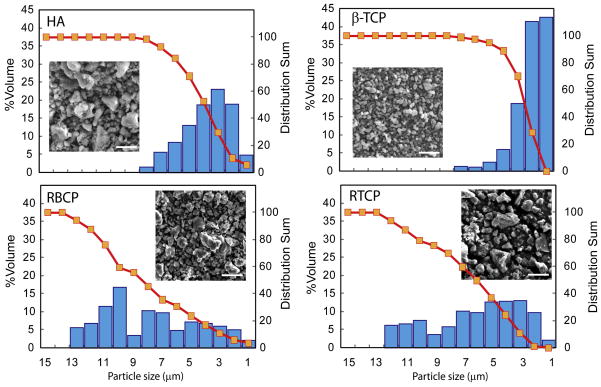
We have prepared dense ceramics and porous scaffolds using three different calcium phosphate materials: HA (TransTech, USA), β-TCP (Keramat, Spain), and biphasic (35/65, HA/β-TCP, Keramat, Spain). The later was synthesized separately using a chemical precipitation method similar to that described by Reynaud et al. [35]. The characteristics of the powders are summarized in Table 1. The particle-size distribution was measured by centrifugal photo-sedimentation (Capa 700, Horiba Instruments Inc., Irvine, CA, USA) and the specific surface area by the Brunauer, Emmett & Teller (BET) technique (Tristar BET, Micromeritics Instrument Corp., GA, USA). The particle shape was analyzed by scanning electron microscopy (SEM [Hitachi FE-SEM-4300EN]). The chemical composition and phase distribution were determined using X-ray diffraction (XRD [Siemens D-500, Cu Kα1 λ = 1,5406 Å, 30 mA/40 kV]) and energy dispersive spectroscopy in the SEM (SEM-EDS). The particle-size distribution of the “as received” ceramics was modified by firing and subsequently grinding pellets prepared by uniaxially pressing the starting powders at 200 MPa (Wabash Hydraulic Press 30-12 12T, Wabash Met Co., IN, USA) followed by cold isostatic pressing (CIP) at 4 GPa. The pellets were fired for 2 hours at 1,000°C (BCP) or 1,100°C (β-TCP). The sintered pellets were crushed and milled with alumina balls in isopropyl alcohol, and the resulting powders were sieved through a 43 μm mesh. These resized materials are named RTCP and RBCP to distinguish them from the “as received” powders (Fig. 1).
Table 1.
Average particle size and specific surface area of the starting powders.
| Powder | Average particle size (μm) | Specific surface area (m2/g) |
|---|---|---|
| HA | 2.4 | 3.3 |
| β-TCP | 1.6 | 2.16 |
| BCP (35/65, HA/β-TCP) | 0.6 | 12.4 |
| RTCP | 4.94 | 1.95 |
| RBCP (35/65, HA/β-TCP) | 5.74 | 1.69 |
Figure 1.
Grain-size distribution of the starting ceramic powders. Resizing results in a significantly wider distribution(the line is 5 μm in all the pictures)
Dense ceramic samples for mechanical testing and microstructural assessment were prepared by cold isostatic pressing at 1.4 GPa followed by sintering in air at 1,085°C (BCP), 1,100°C (β-TCP), and 1,200°C (HA) with a 5°C·min−1 heating rate and dwell time of 2 hours. The densities were determined by the Archimedes method. Six rectangular bending specimens (25 × 6.5 × 2.5 mm) were cut from each sample using a low-speed diamond saw (IsoMet, Buehler LTD, Lake Bluff, IL, USA). Flexural strengths (N=5) were measured in four-point bending on a servohydraulic testing machine (MTS 810, MTS Systems, Eden Prairie, MN, USA) at a displacement rate of 1 μm/s. Plane-strain fracture toughness (KIc) measurements (N=5) were performed on single-edge notched bend, SE(B), specimens loaded in three-point bending. The notches were first introduced using a low-speed diamond saw, and then sharpened using a razor micronotching technique. Micronotches, with root radius ~5 μm, were obtained by repeatedly sliding a razor blade over the saw-cut notch using a custom-made rig, while continually irrigating with a 1 μm diamond slurry. KIc values were determined by monotonically loading the specimens to failure under displacement control with a displacement rate of 1 μm/s. All toughness tests satisfied the plane-strain and small-scale yielding requirements for valid KIc measurements, as per ASTM Standard E399-06. In addition, Vickers diamond microhardness was also used to assess the toughness by inducing radial cracks in the material. Measured crack lengths were correlated to Kc through the semi-experimental relationship [36]:
| [1] |
where P is the applied load (here P = 150–200 g), E the Young’s modulus, H the Vickers hardness, a the radial crack length measured from the center of the indent, and χ an empirically determined calibration constant taken to be 0.016±0.004. Vickers hardness was measured with a load of 100 g, which ensured no radial crack formation. The fracture toughness of these materials can be characterized with a single-value toughness, i.e., KC = KIC, since no R-curve behavior is to be expected, given the small grain size. This was further validated by examination of the fracture surfaces that display transgranular fracture.
2.2. Ink Preparation
The inks were created by mixing ceramic powders with Pluronic® F-127 solutions. Pluronic solutions exhibit a reverse thermal behavior: they are fluid at low temperatures (close to 0°C) but a soft gel at room temperature. The solutions were prepared by mixing the Pluronic powders with water for 5 hours using zirconia balls in a shaker (Red Devil 5400, Red Devil Equipment Co., Plymouth, MN, USA). Subsequently, they were cooled to 0°C in a water/ice bath and filtered through a 100 μm mesh to break aggregates. Afterward, sonication inside the water/ice bath was used to eliminate air bubbles. The ceramic powders were added while maintaining the solution at ~0°C inside an ice/water bath to ensure the complete reverse gellation process and lower the viscosity. The powders are dispersed with the help of an 800W stirrer with variable speed (Dewalt DW236, 0–800 rpm). 1-Octanol (Sigma-Aldrich, St Louis, MO, USA) (2.5 wt% of the water content) [28] was also added to help eliminate air bubbles. After dispersing the ceramic powders, commercial corn syrup (Karo, 4 wt% related to the water content) was added to enhance adhesion between printed lines. In order to ensure homogeneity, the inks were mixed thoroughly for 10 min in the water/ice bath and afterward sieved through a 100 μm mesh to minimize the presence of aggregates. The inks were loaded into a 10 ml syringe (BD, Franklin Lakes, NJ, USA) with an HD-PTFE custom-sized plunger. The syringes were gently tapped from the bottom to move remaining bubbles to the top. Three different inks were prepared for each powder using 10 wt%, 20 wt%, and 30 wt% Pluronic® F-127 solutions (Table 2).
Table 2.
Composition of the robocasting inks (vol%). HA stands for “as received” HA, RT for resized β-TCP, RB for resized BCP, and T for the “as received” β-TCP powders.
| HA10 | HA20 | HA30 | RT10 | RT20 | RT30 | T20 | T30 | RB20 | RB30 | |
|---|---|---|---|---|---|---|---|---|---|---|
| HA | 51.91 | 47.03 | 43.80 | - | - | - | - | - | - | - |
| β-TCP | - | - | - | 44.92 | 41.92 | 37.33 | 35.37 | 32.92 | - | - |
| BCP | - | - | - | - | - | - | - | - | 41.71 | 38.07 |
| DIW | 41.01 | 41.11 | 39.10 | 46.96 | 45.08 | 43.60 | 50.16 | 46.67 | 45.25 | 43.09 |
| F127 | 3.80 | 8.57 | 13.97 | 4.36 | 9.39 | 15.58 | 10.45 | 16.67 | 9.43 | 15.39 |
| C. Syrup | 1.91 | 1.92 | 1.82 | 2.19 | 2.10 | 2.03 | 2.34 | 2.18 | 2.11 | 2.01 |
| 1-Octanol | 1.37 | 1.37 | 1.30 | 1.57 | 1.50 | 1.45 | 1.67 | 1.56 | 1.51 | 1.44 |
2.3. Printing and Testing
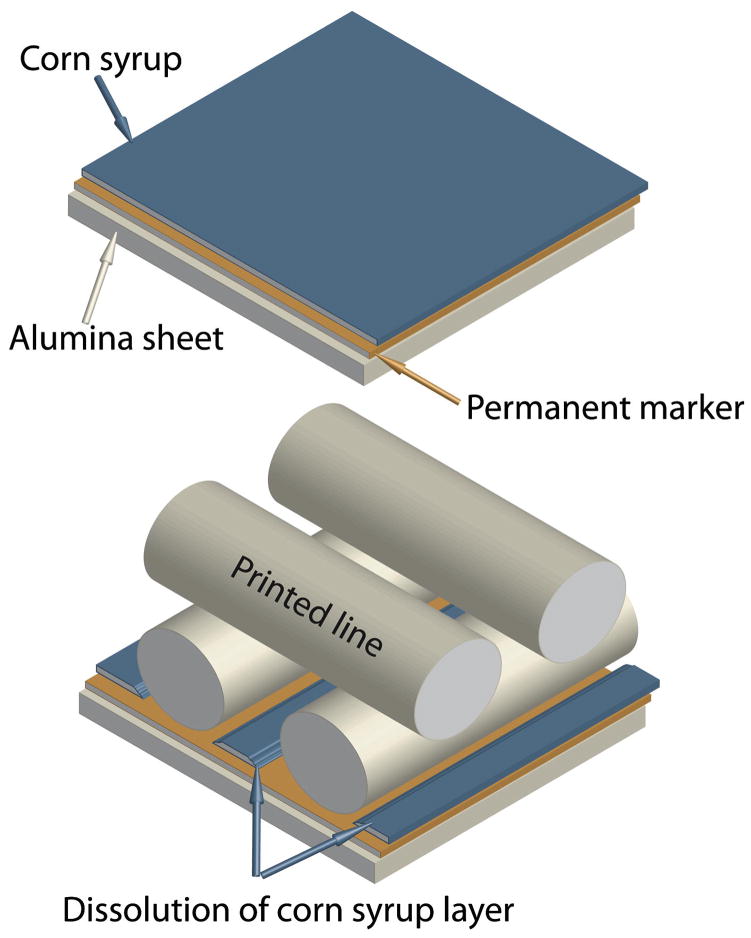
The inks were used to print standard ceramic grids using a robotic deposition device (Robocad 3.0, 3-D Inks, Stillwater, OK, USA). The diameter of the printing nozzles ranged from 100 μm to 250 μm (EFD precision tips, EFD, RI, USA). The scaffolds were printed inside a reservoir of non-wetting oil (Lamplight®, Menomonee Falls, WI, USA) over an Al2O3 plate (~1 mm thick). A key step is to achieve a certain degree of adhesion between the substrate and the first printed line such that the scaffold remains stable during printing while allowing at the same time an easy removal afterward; this will facilitate handling and avoid deformations due to uneven shrinkage during drying and sintering. Here, this is achieved by sequentially applying an oil-soluble hydrophobic layer (permanent marker, Sharpie, Sanford) and a water-soluble hydrophilic layer (corn syrup spin-coated in two steps: 30 seconds at 500 rpm and 2 minutes at 3,000 rpm using WS-400B-6NPP-LITE coater from Laurell Technologies Corp., North Wales, PA, USA) on the substrate (Fig. 2). The ink adheres to the hydrophilic film. However, the water in the ink progressively dissolves the sugar, exposing the hydrophobic layer to the oil. When the oil dissolves this hydrophobic layer, the printed structures self-detach from the alumina substrate. After printing, the samples were dried and sintered on the alumina plates. First, the plates were tilted (~45°) to drain the excess oil. After drying for 24 hours at room temperature, the pieces were fired at 600°C (1°C min−1, heating rate) for 2 hours to evaporate the organics, followed by sintering for two hours at 1,085°C, 1,100°C, and 1,275°C for BCP, β-TCP, and HA with a heating and cooling rate of 5°C min−1.
Figure 2.
The alumina substrates are covered with a double hydrophophic (permanent marker)–hydrophilic (corn syrup) layer that promotes adhesion during printing but dissolves in a controlled manner afterward to facilitate removal of the sample and avoid the generation of drying and sintering stresses.
The pressures needed to make the inks flow through the printing nozzles were measured in a universal test machine using 1 ml syringes with an internal diameter of 4.5 mm (BD, Franklin Lakes, NJ, USA) and cylindrical or conical tips with diameters varying from 100 to 450 μm. The pressures were measured at a constant displacement rate for the syringe piston (vp). The equivalent printing velocities, vw, can be calculated considering a constant flow from the syringe chamber and the ratio between the tip (φt) and syringe (φs) diameters:
| [2] |
The equivalent printing velocities varied from 4 to 15 mm s−1, and are of the order of the ones used during printing.
The mechanical strength of standard grids (15 × 3 × 1.5 mm) printed through a 200 μm tip, with a bandwidth gap of 200 μm between lines and a layer height of 180 μm, was measured in three-point bending (N=20). The microstructure of the fracture surfaces and polished cross sections (finished with 1 μm diamond) were examined by FE-SEM. The microporosity of the printed layers was quantified used automated image analysis (Image J, v. 1.40g, NIH, USA) of backscattered electron microscopy images. Ten measurements were made for each sample and composition. The sintering and drying shrinkages in the different directions were determined using optical images with an average of 80 measurements per direction.
3. Results and Discussion
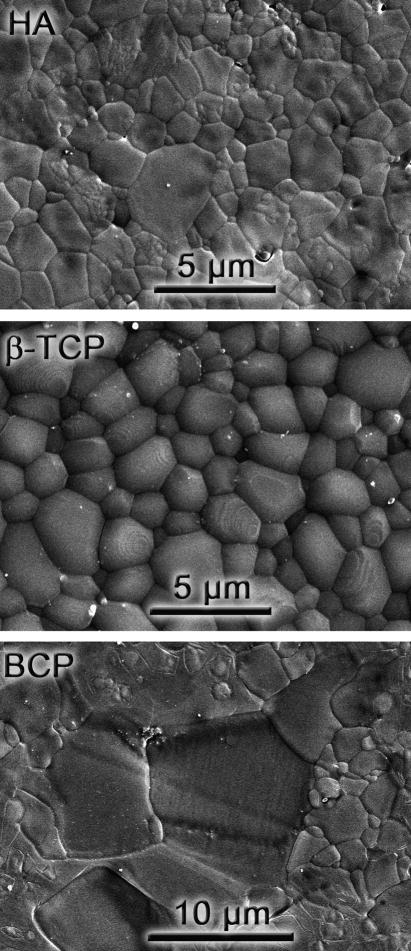
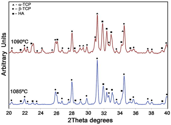
All dense materials exhibit relative densities above 97%, even the BCP ceramics that are relatively more difficult to sinter. This is in part due to the high pressures used during CIP that result in large green densities. Table 3 summarizes their mechanical properties. The BCP bars cracked during notching, and their toughness could only be determined using indentation. Their low indentation KIC value (0.48 MPa√m) is consistent with the difficulties observed in the preparation of notched samples. Overall, the mechanical properties are in basic agreement [37, 38] with results previously reported for calcium phosphates. However, the properties of the biphasic material (strength and toughness) are significantly lower than that of its components. This could be explained, in part, by the abnormal grain growth observed in the BCP. While sintered HA and β-TCP exhibit a very homogeneous microstructure with grain sizes in the range of 1–5 μm, BCP developed a very wide grain-size distribution that alternates 1 μm grains with others of the order of the tens of microns (Fig. 3). There have been indications that the Ca/P ration has a strong effect on the sintering and grain growth behavior of calcium phosphates [29]. Abnormal grain growth has also been observed in other calcium phosphate biphasic materials (TCP/Ca2P2O7 Ca/P=1.44) and can also be triggered by different dopants [39, 40]. In addition, the sintering temperature of BCP was kept below 1,085°C to avoid transformation of the tricalcium phosphate into the more soluble α phase. This transformation is usually associated with the generation of microcracks due to the volume changes [41]. The observed transformation temperature in the biphasic material (~1,090°C, Fig. 4) is lower than those reported for pure TCP (typically between 1,125°C to 1,175°C) including the pure TCP powders used in this work [42–44].
Table 3.
Density and mechanical properties of the dense ceramics.
| Material | Density, ρ % th. | Flexural strength, σf (MPa) | Initiation toughness, KIC (MPa. √m) | Vickers hardness, Hv (GPa) | |
|---|---|---|---|---|---|
| 3-point bending | Indentation | ||||
| β-TCP | 99 | 102±13 | 1.16±0.16 | 1.28±0.32 | 4.737 |
| HA | 97 | 77±20 | 0.72±20 | 0.91±0.23 | 4.880 |
| BCP | 98 | 34±3.7 | - | 0.48±0.12 | 4.256 |
Figure 3.
Microstructures of the dense calcium phosphates after polishing and thermal etching (2 hours at 1,000°C).
Figure 4.
The X-ray diffraction analysis of the sintered BCP materials only shows β-TCP and HA in the samples fired at 1,085°C but reveals the formation of α-TCP in samples fired at 1,090°C.
The rheological properties of the inks are mainly determined by the concentration of Pluronic®, and the concentration and particle-size distribution of the ceramic powders. The ceramic particles are mixed with Pluronic® F-127 solutions at low temperature (~0°C) where they are very fluid, and the copolymer blocks (polyethylene oxide-propylene oxide-polyethylene oxide) are dissolved in water, allowing good ceramic dispersion and homogenization. Printing is done at room temperature, where the copolymer blocks reorganize to form micelle aggregates and create a gel that encapsulates the particles. This behavior is due to the decrease of the degree of hydrogen bonding between the water and the OH groups of the polypropylene oxide units when the temperature increases [45].
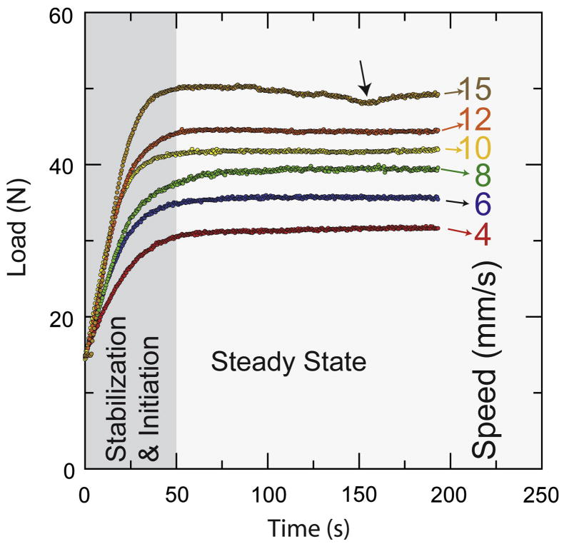
The optimum inks should exhibit a pseudoplastic behavior. Flow is initiated when a threshold yield stress is exceeded [46]. The inks then flow steadily under stress but settle immediately after printing. A typical load vs. time curve taken while the syringe piston descends at constant velocity (Fig. 5) shows two differentiated zones: (1) initiation of flow with alignment and equilibration of the system, and (2) steady-state flow. These curves give us information about the time needed to achieve a steady flow and the level of pressure during printing, providing useful information to guide the printing process and the selection of inks.
Figure 5.
Load vs. time flow curves for the HA20 ink printed through a 200 μm nozzle at different printing speeds. Initially the system equilibrates and flow starts (shadowed zone) until a steady-state situation is achieved. Bubbles in the ink can lead to small drops in pressure during printing (see arrow).
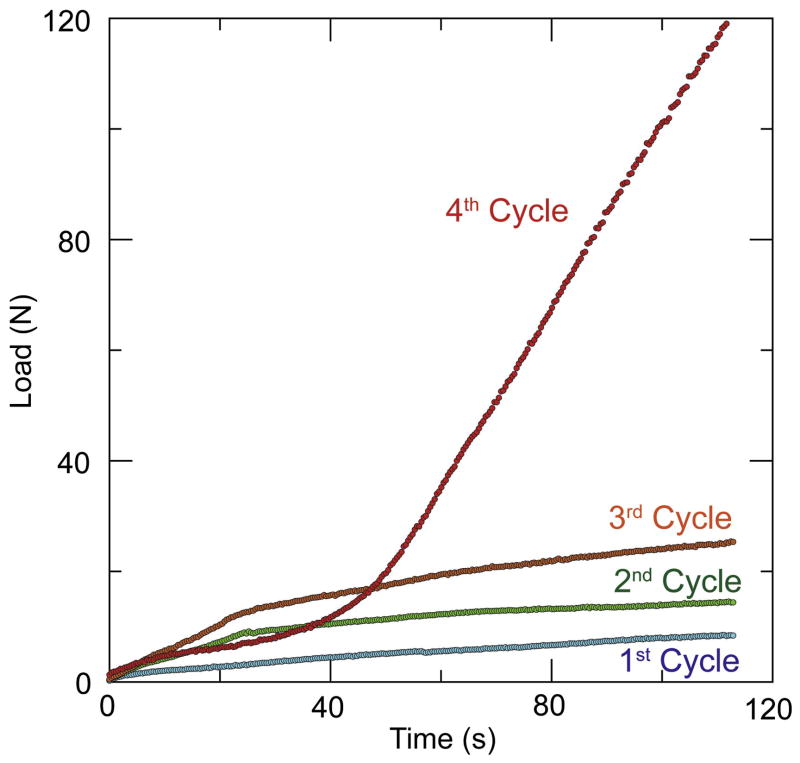
All the inks need more than 30 seconds to reach the steady state. This means that when printing starts, the tip should move an appreciable distance before establishing a stable flow; for example, for the slowest printing speed (4 mm s−1), this distance is 120 mm. In order to accelerate equilibration, a small overpressure is applied before printing. Pluronic® F-127 aqueous solutions form thermo-reversible gels when the concentration is 20 wt% or more [47]. In the 10 wt% solutions (RT10 and HA 10), there is not enough micelle aggregation; therefore, liquid migrates during printing due to the applied pressure. The loss of water leads to a steady increase of the load as the piston moves. Eventually, the material becomes locally dry and clogs the printing nozzle (Fig. 6). As a consequence, it was necessary to put fresh ink in the syringe after printing each standard piece using the RT10 and HA10 inks, whereas for inks with larger Pluronic contents it was possible to use the full syringe volume without reloading. Opposite to some formulations of polymer inks that use Pluronic block copolymers adsorbed to the surface of polymer particles as a gelling agent to create a colloidal gel [48] (a similar approach to the use of the interaction between ammonium polyacrylate based dispersants and ionized PEI to create a ceramic gel [28–30]), here the ceramic particles are immersed in the Pluronic gel. As a consequence the Pluronic content in the ceramic inks are much larger but ink formulation is practically independent of the particle surface chemistry.
Figure 6.
Flow curves for the RT10 ink corresponding to an equivalent printing speed of 12 mm. s−1. The curves show the effect of solvent migration. The printing load increases and does not reach a steady state and increases with increasing number of cycles (each cycle corresponds with a printing time of 200 s). After four cycles, the nozzle clogged and the remaining ink inside the syringe was completely dry.
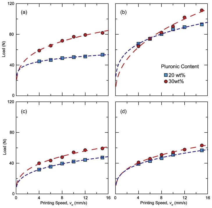
Inks with 20 to 30 wt% Pluronic reach a steady state in which the load on the piston is in equilibrium with the flow resistance at every printing speed. There is not an appreciable decrease in force with travel of the ram, suggesting that stresses at the syringe walls do not play a significant role, and that printing at constant pressure is equivalent to printing at constant piston speed. All the inks exhibit a non-Newtonian behavior, where the relationship between the printing load L and the piston speed follows a simple power law, L= A vpn [49]. All the inks exhibit n<1, which corresponds to a pseudoplastic behavior (Table 4).
Table 4.
Flow consistency and behavior indexes for the different inks (load in N and v in mms−1). The corresponding fitting coefficients are also shown.
| HA20 | HA30 | T20 | T30 | RB20 | RB30 | RT20 | RT30 | |
|---|---|---|---|---|---|---|---|---|
| Consistency I. (A) | 20.67 | 24.85 | 47.90 | 35.4 | 37.03 | 41.17 | 25.92 | 25.93 |
| Behavior I. (n) | 0.307 | 0.324 | 0.249 | 0.417 | 0.132 | 0.261 | 0.288 | 0.323 |
| Fitting coeff. | 0.99 | 0.99 | 0.99 | 0.99 | 0.99 | 0.98 | 0.99 | 0.99 |
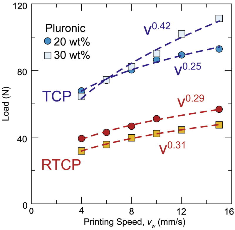
Ideally, both the flow consistency index (A) and the behavior index (n) should be low such that a wide range of printing speeds can be reached using relatively low pressures. The behavior of the inks depends on the Pluronic concentration and the particle-size distribution. Due to the higher micelle aggregation, inks with larger Pluronic contents (30 wt%) tend to require larger printing pressure (Fig. 7) and exhibit larger behavior index. However, the granulometry of the ceramic powders also exerts a large influence, mostly through the flow consistency index. For example, the behavior index of inks prepared with “as received” and resized β-TCP powders (Fig. 8) are similar, but the consistency indexes for the “as received” powder are almost double. In addition, in all our formulations, the solid content of the ink has been maximized while allowing steady-state flow without liquid migration. Still, the T20 ink (prepared with “as received” powders) has a solid loading content ~13 vol% smaller than RT20 ink (prepared with a resized material). The only difference between these two powders is their grain-size distribution (Fig. 1). All the different ceramic powders used in the formulation of inks exhibit an equiaxed morphology. However, T20 powders have a narrower distribution and smaller average grain size (1.58 μm) whereas in resized tricalcium phosphate (RTCP), the average grain size is 4.94 μm with a much wider distribution. Overall, powders with wide particle-size distributions (e.g. HA and RTCP) resulted in inks with lower consistency indexes. For example, although the HA powders have a higher surface area than “as received’ β-TCP powders (3.31 and 2.31 m2/g, respectively), their grain-size distribution is significantly wider, and inks prepared from HA powders have larger solid concentrations and smaller flow pressure than inks prepared from β-TCP.
Figure 7.
Comparison of load vs. printing speed values for inks with 20 wt% and 30 wt% Pluronic® F-127 content. (a) Hydroxyapatite (HA). (b) β-TCP (T). (c) Resized β-TCP (RT). (d) Resized biphasic powders (RB). All the inks have a pseudoplastic behavior adequate for the robotic-assisted deposition process.
Fig 8.
Load vs. time flow curves for “as received” β-TCP powders and resized powders. Narrow grain-size distributions result in worse packing and higher flow resistance.
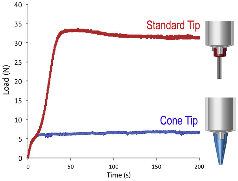
Chen et al. [50] have studied the influence of the grain-size distribution in the extrusion process. When employing wide particle-size distributions, the smaller particles facilitate the slip and rearrangement of the bigger ones during extrusion, favoring flow through the narrow tips. The results are inks with larger solid contents, lower consistency indexes, and an overall drop in the extrusion pressures. When the distributions are narrow and most particles have similar diameters, the interparticle voids cannot be filled and the solid content decreases. The other key parameter is the geometry of the printing nozzle. The use of conical tips diminishes the presence of dead zones along the extrusion path and decreases substantially the printing pressures (Fig. 9) as previously described by Benbow [51]. However, due to their abrasive nature, the ceramic inks tend to progressively widen the narrow hole at the end of the conical nozzle, compromising the printing precision.
Figure 9.
Load vs. time curves for HA20 inks through a standard metallic tip and a conical plastic l-tip. The extrusion load drops almost one order of magnitude when printing with a conical tip.
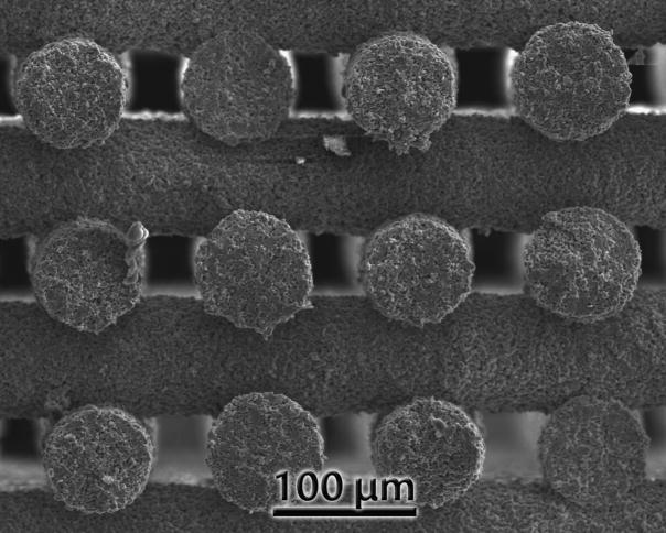
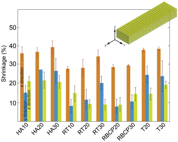
All the ink compositions tested were successfully printed through nozzles as narrow as 150 μm in diameter. The HA20 ink can also be printed through a 100 μm tip (Fig. 10). In this case, slow printing speeds (<2 mm. s−1) have to be used, and the nozzle has to be periodically cleaned to avoid clogging. Shrinkage during sintering was not homogeneous in all directions (Fig. 11). Larger shrinkage occurred along the X dimension and increased with the Pluronic content. Inks with worse particle packing (e.g., those prepared using BCP) or with partial water migration due to lower Pluronic contents exhibited larger Z shrinkage. This is due to deformation and bending of the printed filaments with the subsequent decrease in height between lines (Fig. 12).
Figure 10.
HA structure printed through a 100 μm tip using the HA20 ink. The line diameter after sintering is of the order of 80 μm.
Figure 11.
Sintering shrinkage of the grids in the different directions. In the printed structure, X and Y follow the printing direction whereas Z is related to the thickness of the printed line.
Figure 12.
SEM micrographs showing a comparison between the T30 and BCP20 fracture surfaces. Both printed lines have similar porosity (~24 vol%), but the transversal lines for the BCP20 are bent due to their lower green strength.
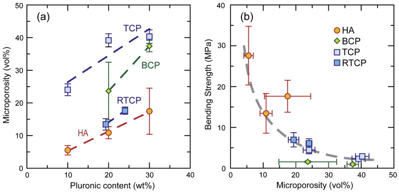
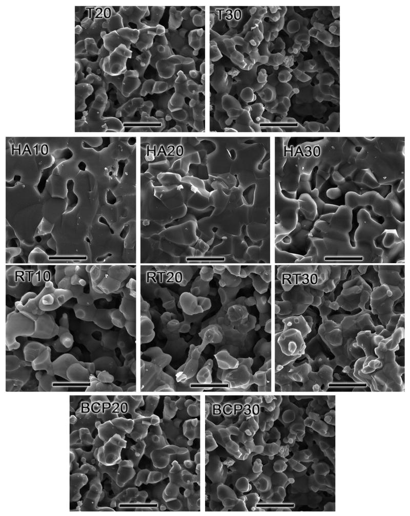
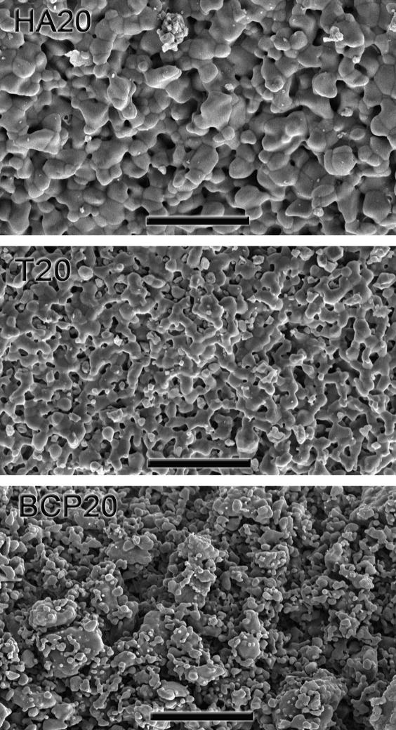
The microporosity of the scaffold walls has a significant effect on the cellular response to the implanted materials [32–34]. Polystyrene porogens or variations in the sintering temperature have been used to control the porosity in the printed lines of structures built using solid-free-form fabrication techniques [52–54]. In addition, the density of the printed lines determines to a great extent the mechanical strength (Fig. 13). Line density can be controlled by the amount of Pluronic, the granulometry of the starting powders (the particle packing), and the sintering temperature. An increase in Pluronic content results in a decrease of the density of the printed line, as can be expected from the larger organic content of the inks (Figs. 13–14). The sintering temperatures are limited by the decomposition of the HA or the α→β transformation of the tricalcium phosphate. The volume changes associated with the transformation can result in the formation of microcracks that are detrimental to the mechanical response [29] and the β phase is typically preferred over the more soluble α one. As a result BCP and TCP grids have larger microporosity. In addition, and as for the dense pieces, abnormal grain growth in the printed BCP grids further limits their densification (Fig. 15).
Figure 13.
(a) The overall microporosity of the printed lines (measured using automated image analysis from backscattered electron microscopy images) increases with increasing Pluronic content in the inks. (b) Microporosity determines to a great extent the final strength.
Figure 14.
SEM micrographs of fracture surfaces for all the compositions printed. HA materials have much lower microporosity. The scale bar is 5 μm.
Figure 15.
Comparison of the surface microporosities in HA20, T20, and BCP20 sintered pieces. The BCP material exhibits a much larger microporosity as well as a wider grain-size distribution. Scale bar is 20 μm.
4. Conclusions
Pluronic® F-127 solutions have been used to prepare water-based calcium phosphate inks suitable for printing 3D scaffolds by robotic-assisted deposition. Because Pluronic® F-127 is a non-ionic block copolymer, inks with a high-volume content of ceramics can be prepared in a single step without manipulating the pH of the slurries. The two main parameters that control the response of the inks and the microstructure of the printed scaffolds are the Pluronic content and the granulometry of the powders; they affect the flow resistance, the microporosity of the scaffolds and their mechanical properties. Wider grain-size distributions allow the fabrication of better-flowing inks with larger solid content. Larger Pluronic content enhances ink stability but also results in larger microporosities and lower mechanical strength. This approach can be used to manipulate the microstructure and composition of ceramic scaffolds, allowing the fabrication of materials tailored for specific applications.
Acknowledgments
This work was supported by the National Institutes of Health (NIH) under Grant No. 5R01 DE015633.
References
- 1.Hench LL. Bioceramics. J Am Ceram Soc. 1998;81:1705. [Google Scholar]
- 2.Sen MK, Miclau T. Autologous iliac crest bone graft: Should it still be the gold standard for treating nonunions? Injury. 2007;38:S75. doi: 10.1016/j.injury.2007.02.012. [DOI] [PubMed] [Google Scholar]
- 3.Silber JS, Anderson DG, Daffner SD, Brislin BT, Leland JM, Hilibrand AS, Vaccaro AR, Albert TJ. Donor site morbidity after anterior iliac crest bone harvest for single-level anterior cervical discectomy and fusion. Spine. 2003;28:134. doi: 10.1097/00007632-200301150-00008. [DOI] [PubMed] [Google Scholar]
- 4.Tomford WW. Bone allografts: past, present and future. Cell and Tissue Banking. 2000;1:105. doi: 10.1023/A:1010158731885. [DOI] [PubMed] [Google Scholar]
- 5.Legeros RZ, Lin S, Rohanizadeh R, Mijares D, Legeros JP. Biphasic calcium phosphate bioceramics: preparation, properties and applications. J Mater Sci-Mater M. 2003;14:201. doi: 10.1023/a:1022872421333. [DOI] [PubMed] [Google Scholar]
- 6.Oonishi H, Hench LL, Wilson J, Sugihara F, Tsuji E, Kushitani S, Iwaki H. Comparative bone growth behavior in granules of bioceramic materials of various sizes. J Biomed Mater Res. 1999;44:31. doi: 10.1002/(sici)1097-4636(199901)44:1<31::aid-jbm4>3.0.co;2-9. [DOI] [PubMed] [Google Scholar]
- 7.Dorozhkin SV. Calcium orthophosphates. J Mater Sci. 2007;42:1061. [Google Scholar]
- 8.Giannoudis PV, Dinopoulos H, Tsiridis E. Bone substitutes: An update. Injury. 2005;36:20. doi: 10.1016/j.injury.2005.07.029. [DOI] [PubMed] [Google Scholar]
- 9.Arinzeh TL, Tran T, Mcalary J, Daculsi G. A comparative study of biphasic calcium phosphate ceramics for human mesenchymal stem-cell-induced bone formation. Biomaterials. 2005;26:3631. doi: 10.1016/j.biomaterials.2004.09.035. [DOI] [PubMed] [Google Scholar]
- 10.Hulbert SF, Morrison SJ, Klawitte Jj. Tissue Reaction to 3 Ceramics of Porous and Non-Porous Structures. J Biomed Mater Res. 1972;6:347. doi: 10.1002/jbm.820060505. [DOI] [PubMed] [Google Scholar]
- 11.Langer R, Vacanti JP. Tissue Engineering. Science. 1993;260:920. doi: 10.1126/science.8493529. [DOI] [PubMed] [Google Scholar]
- 12.Driessens FCM. Formation and stability of calcium phosphates in relation to the phase composition of the mineral calcified tissues. In: De Groot K, editor. Bioceramics of Calcium Phosphate. Boca Raton, Florida: CRC press; 1983. p. 1. [Google Scholar]
- 13.Daculsi G, Legeros RZ, Nery E, Lynch K, Kerebel B. Transformation of Biphasic Calcium-Phosphate Ceramics Invivo - Ultrastructural and Physicochemical Characterization. J Biomed Mater Res. 1989;23:883. doi: 10.1002/jbm.820230806. [DOI] [PubMed] [Google Scholar]
- 14.Miranda P, Pajares A, Saiz E, Tomsia AP, Guiberteau F. Mechanical properties of calcium phosphate scaffolds fabricated by robocasting. J Biomed Mater Res A. 2008;85A:218. doi: 10.1002/jbm.a.31587. [DOI] [PubMed] [Google Scholar]
- 15.Kuznetsov SA, Huang KE, Marshall GW, Robey PG, Mankani MH. Long-term stable canine mandibular augmentation using autologous bone marrow stromal cells and hydroxyapatite/tricalcium phosphate. Biomaterials. 2008;29:4211. doi: 10.1016/j.biomaterials.2008.07.013. [DOI] [PMC free article] [PubMed] [Google Scholar]
- 16.Alam MI, Asahina I, Ohmamiuda K, Enomoto S. Comparative study of biphasic calcium phosphate ceramics impregnated with rhBMP-2 as bone substitutes. J Biomed Mater Res. 2001;54:129. doi: 10.1002/1097-4636(200101)54:1<129::aid-jbm16>3.0.co;2-d. [DOI] [PubMed] [Google Scholar]
- 17.Saiz E, Gremillard L, Menendez G, Miranda P, Gryn K, Tomsia AP. Preparation of porous hydroxyapatite scaffolds. Mat Sci Eng C-Bio S. 2007;27:546. [Google Scholar]
- 18.Ben-Nissan B. Natural bioceramics: from coral to bone and beyond. Curr Opin Solid St M. 2003;7:283. [Google Scholar]
- 19.Bohner M, van Lenthe GH, Grunenfelder S, Hirsiger W, Evison R, Muller R. Synthesis and characterization of porous beta-tricalcium phosphate blocks. Biomaterials. 2005;26:6099. doi: 10.1016/j.biomaterials.2005.03.026. [DOI] [PubMed] [Google Scholar]
- 20.Sous M, Bareille R, Rouais F, Clement D, Amedee J, Dupuy B, Baquey C. Cellular biocompatibility and resistance to compression of macroporous beta-tricalcium phosphate ceramics. Biomaterials. 1998;19:2147. doi: 10.1016/s0142-9612(98)00118-5. [DOI] [PubMed] [Google Scholar]
- 21.Deville S, Saiz E, Tomsia AP. Freeze casting of hydroxyapatite scaffolds for bone tissue engineering. Biomaterials. 2006;27:5480. doi: 10.1016/j.biomaterials.2006.06.028. [DOI] [PubMed] [Google Scholar]
- 22.Leong KF, Cheah CM, Chua CK. Solid freeform fabrication of three-dimensional scaffolds for engineering replacement tissues and organs. Biomaterials. 2003;24:2363. doi: 10.1016/s0142-9612(03)00030-9. [DOI] [PubMed] [Google Scholar]
- 23.Hollister SJ. Porous scaffold design for tissue engineering. Nat Mater. 2005;4:518. doi: 10.1038/nmat1421. [DOI] [PubMed] [Google Scholar]
- 24.Duoss EB, Twardowski M, Lewis JA. Sol-gel inks for direct-write assembly of functional oxides. Adv Mater. 2007;19:3485. [Google Scholar]
- 25.Cesarano J. In: Robocasting of ceramics and composites using fine particle suspensions. Laboratory SN, editor. 1999. [Google Scholar]
- 26.Marchi CS, Kouzeli M, Rao R, Lewis JA, Dunand DC. Alumina-aluminum interpenetrating-phase composites with three-dimensional periodic architecture. Scripta Mater. 2003;49:861. [Google Scholar]
- 27.Smay JE, Cesarano J, Lewis JA. Colloidal inks for directed assembly of 3-D periodic structures. Langmuir. 2002;18:5429. [Google Scholar]
- 28.Michna S, Wu W, Lewis JA. Concentrated hydroxyapatite inks for direct-write assembly of 3-D periodic scaffolds. Biomaterials. 2005;26:5632. doi: 10.1016/j.biomaterials.2005.02.040. [DOI] [PubMed] [Google Scholar]
- 29.Miranda P, Saiz E, Gryn K, Tomsia AP. Sintering and robocasting of beta-tricalcium phosphate scaffolds for orthopaedic applications. Acta Biomater. 2006;2:457. doi: 10.1016/j.actbio.2006.02.004. [DOI] [PubMed] [Google Scholar]
- 30.Smay JE, Gratson GM, Shepherd RF, Cesarano J, Lewis JA. Directed colloidal assembly of 3D periodic structures. Adv Mater. 2002;14:1279. [Google Scholar]
- 31.Yang HY, Yang SF, Chi XP, Evans JRG. Fine ceramic lattices prepared by extrusion freeforming. J Biomed Mater Res B. 2006;79B:116. doi: 10.1002/jbm.b.30520. [DOI] [PubMed] [Google Scholar]
- 32.Deligianni DD, Katsala ND, Koutsoukos PG, Missirlis YF. Effect of surface roughness of hydroxyapatite on human bone marrow cell adhesion, proliferation, differentiation and detachment strength. Biomaterials. 2001;22:87. doi: 10.1016/s0142-9612(00)00174-5. [DOI] [PubMed] [Google Scholar]
- 33.Kieswetter K, Schwartz Z, Dean DD, Boyan BD. The role of implant surface characteristics in the healing of bone. Crit Rev Oral Biol M. 1996;7:329. doi: 10.1177/10454411960070040301. [DOI] [PubMed] [Google Scholar]
- 34.Li XM, van Blitterswijk CA, Feng QL, Cui FZ, Watari FM. The effect of calcium phosphate microstructure on bone-related cells in vitro. Biomaterials. 2008;29:3306. doi: 10.1016/j.biomaterials.2008.04.039. [DOI] [PubMed] [Google Scholar]
- 35.Raynaud S, Champion E, Bernache-Assollant D, Thomas P. Calcium phosphate apatites with variable Ca/P atomic ratio I. Synthesis, characterisation and thermal stability of powders. Biomaterials. 2002;23:1065. doi: 10.1016/s0142-9612(01)00218-6. [DOI] [PubMed] [Google Scholar]
- 36.Anstis GR, Chantikul P, Lawn BR, Marshall DB. A Critical-Evaluation of Indentation Techniques for Measuring Fracture-Toughness. 1. Direct Crack Measurements. J Am Ceram Soc. 1981;64:533. [Google Scholar]
- 37.Akao M, Aoki H, Kato K. Mechanical-Properties of Sintered Hydroxyapatite for Prosthetic Applications. J Mater Sci. 1981;16:809. [Google Scholar]
- 38.Akao M, Aoki H, Kato K, Sato A. Dense Polycrystalline Beta-Tricalcium Phosphate for Prosthetic Applications. J Mater Sci. 1982;17:343. [Google Scholar]
- 39.Raynaud S, Champion E, Lafon JP, Bernache-Assollant D. Calcium phosphate apatites with variable Ca/P atomic ratio III. Mechanical properties and degradation in solution of hot pressed ceramics. Biomaterials. 2002;23:1081. doi: 10.1016/s0142-9612(01)00220-4. [DOI] [PubMed] [Google Scholar]
- 40.Lin FH, Liaw JR, Hon MH, Wang CY. The Effects of Na4P2O7-Center-Dot-10H(2)O Addition on the Mechanical-Properties of Sintered Ca2P2O7 Bioceramic. Mater Chem Phys. 1995;41:110. [Google Scholar]
- 41.Case ED, Smith IO, Baumann MJ. Microcracking and porosity in calcium phosphates and the implications for bone tissue engineering. Mat Sci Eng a-Struct. 2005;390:246. [Google Scholar]
- 42.Eanes ED. Thermochemical Studies on Amorphous Calcium Phosphate. Calc Tiss Res. 1970;5:133. doi: 10.1007/BF02017543. [DOI] [PubMed] [Google Scholar]
- 43.Elliott JC. Structure and chemistry of the apatites and other calcium orthophosphates. Amsterdam [The Netherlands]; New York: Elsevier; 1994. [Google Scholar]
- 44.Kreidel ER, Hummel FA. Inorganic Chemistry. 1967;6:891. [Google Scholar]
- 45.Lenaerts V, Triqueneaux C, Quarton M, Riegfalson F, Couvreur P. Temperature-Dependent Rheological Behavior of Pluronic F-127 Aqueous-Solutions. Int J Pharm. 1987;39:121. [Google Scholar]
- 46.Alexandridis P, Hatton TA. Poly(Ethylene Oxide)-Poly(Propylene Oxide)-Poly(Ethylene Oxide) Block-Copolymer Surfactants in Aqueous-Solutions and at Interfaces - Thermodynamics, Structure, Dynamics, and Modeling. Colloid Surface A. 1995;96:1. [Google Scholar]
- 47.Bohorquez M, Koch C, Trygstad T, Pandit N. A study of the temperature-dependent micellization of pluronic F127. J Colloid Interf Sci. 1999;216:34. doi: 10.1006/jcis.1999.6273. [DOI] [PubMed] [Google Scholar]
- 48.Xie BJ, Parkhill RL, Warren WL, Smay JE. Direct writing of three-dimensional polymer scaffolds using colloidal gels. Adv Funct Mater. 2006;16:1685. [Google Scholar]
- 49.Benbow JJ, Oxley EW, Bridgwater J. The Extrusion Mechanics of Pastes - the Influence of Paste Formulation on Extrusion Parameters. Chem Eng Sci. 1987;42:2151. [Google Scholar]
- 50.Chen ZC, Ikeda K, Murakami T, Takeda T. Effect of particle packing on extrusion behavior of pastes. J Mater Sci. 2000;35:5301. [Google Scholar]
- 51.Benbow JJ. Dependence of Output Rate on Die Shape during Catalyst Extrusion. Chem Eng Sci. 1971;26:1467. [Google Scholar]
- 52.Dellinger JG, Cesarano J, Jamison RD. Robotic deposition of model hydroxyapatite scaffolds with multiple architectures and multiscale porosity for bone tissue engineering. J Biomed Mater Res A. 2007;82A:383. doi: 10.1002/jbm.a.31072. [DOI] [PubMed] [Google Scholar]
- 53.Dellinger JG, Wojtowicz AM, Jamison RD. Effects of degradation and porosity on the load bearing properties of model hydroxyapatite bone scaffolds. J Biomed Mater Res A. 2006;77A:563. doi: 10.1002/jbm.a.30658. [DOI] [PubMed] [Google Scholar]
- 54.Yang HY, Yang SF, Chi XP, Evans JRG, Thompson I, Cook RJ, Robinson P. Sintering behaviour of calcium phosphate filaments for use as hard tissue scaffolds. J Eur Ceram Soc. 2008;28:159. [Google Scholar]


