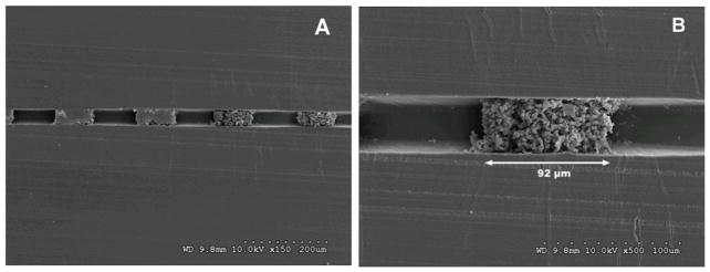
Abstract
In order to increase the extent of reaction for on-chip fluorescent labeling of proteins, a passive mixer has been prepared by using UV light to photopattern a periodic arrangement of porous polymer monolith structures directly within the channel of a plastic microfluidic chip. By optimizing the composition of the polymerization solution and irradiation time we demonstrated the ability to photopattern monoliths in regularly repeating 100 μm segments at the tee-junction of the disposable device. To evaluate the efficiency of this dual functional mixer-reactor, fluorescamine and lysine were introduced in separate channels upstream of the tee-junction and the intensity of laser-induced fluorescence resulting from the fluorogenic labeling reaction was monitored. The fluorescence level after passing the photopatterned periodic monolith configuration was better than both an equivalent 1 cm long continuous monolithic segment and an open channel. These results indicate that the periodic arrangement of monoliths, with regularly spaced open areas between 100 μm plugs, is responsible for enhancing the mixing performance and overall rate of chemical reaction carried out in the system. In addition to facilitating preparation of a dual functional mixer-reactor, the ability to accurately photopattern monoliths in a channel is an enabling technology for seamlessly integrating multiple monoliths into a single microdevice.
Introduction
The miniaturization and adaptation of biochemical analysis to a microfluidic format is driven by several advantages.1 These include a reduction in the consumption of often expensive reagents, short run times, and the ability to perform a large number of analyses simultaneously. Adapting current methods to a chip format also facilitates integration of multiple processes onto a single platform yielding a self-contained and portable micro total analytical system (μTAS) capable of performing sophisticated chemical analyses in the field.1,2 A critical component to device development on this length scale is the ability to control the interaction between the analytes in solution and the surfaces they contact within the chip.3–7
Integrating high surface-area materials is advantageous because it increases the amount of material that the chip can process thereby improving signal strength and analytical reliability. Porous polymer monoliths (PPM) are a class of rigid, large surface area materials with tunable chemical and physical properties that is well suited for microfluidic applications.8–11 The variety of applications that have been demonstrated using monoliths is a testament to the wide range and ease with which their chemistry and pore size can be tuned. These chip-based applications include electrochromatography for protein separations,12–14 reverse phase separations of peptides from protein digests,15 immunochromatography for purification of human serum albumin,16 protein digestion by immobilized enzyme,17 and solid-phase extraction for preconcentration.18–23 The porous structure of monoliths has also been exploited and implemented as a frit for retaining particles,24,25 electrospray emitters for ESI-MS,26–29 in-line heat actuated valves,30–32 and micromixers.33
Mixing the contents of converging streams in a small channel is important to most microfluidic applications. Simultaneously, this operation is challenging because the lack of turbulence in the regime of low Reynolds number flow that makes mixing diffusion-limited and slow.34 Through qualitative measurements of mixing length, Rohr et al. has shown that a continuous 2 cm monolith improved the mixing efficiency of an empty channel and that further enhancement could be achieved by increasing the void fraction within the monoliths. When the porogen content was increased, the pore morphology was transformed from a homogenous to a bimodal pore size distribution with large pores interspersed between curtains of materials featuring small pores.33
A particularly attractive property of monoliths is the ability to spatially define their location in the device through the use of an in situ preparation mediated by UV irradiation through a mask. Tremendous potential lays in the ability to photopattern this diverse class of materials with high precision. For instance, complex fluid control systems consisting of a high-density array of monolithic valves for applications such as single cell metabolic profiling could be prepared using a single exposure. Similarly, high throughput through massive parallel processing could be realized by photopatterning the desired number of monoliths in a single exposure and the device used in applications such as electrochromatographic separation of proteins. High-resolution photopatterning also enables seamless integration of several different monolith types in a zero-dead-volume fashion for building multifunctional devices capable of complex sample processing. Although photopolymerization is the most utilized preparation method for the preparation of monoliths in chips, there has been no attempt to pattern the monolith in segments less than 1 mm long using contact lithography. A laser and focusing optics were used to photopolymerize a polyacrylamide gel 35 but this method is not amenable for building large-scale systems of monoliths.
This work explores the resolution limits for in situ preparation of monoliths by contact lithography. We study the factors affecting the fidelity of pattern transfer between the mask and polymerization solution used for monolith formation. After optimizing the composition of the polymerization solution and irradiation time, we demonstrate the ability to photopattern monoliths with high fidelity by preparing a dual function micromixer-reactor for on-chip labeling reaction. The reactor-micromixer features architecture with 100 μm segments of regularly spaced monoliths intersperse with voids of equal length. The performance of this micromixer is quantitatively evaluated by monitoring the laser-induced fluorescence intensity of the reaction product of fluorescamine and lysine introduced into the tee-junction of a disposable plastic microfluidic chip.
Experimental section
Chip fabrication
The tee-junction microfluidic chip shown in Fig. 1 was prepared via injection molding as previously reported. 36
Fig. 1.
Tee-junction microfluidic chip manufactured by plastic injection molding (A). Schematic for fluorescent labeling lysine with fluorescamine in a tee-junction microfluidic chip. Fluorescamine fluoresces only upon reaction with amines (B).
Briefly, a mold insert defining the channel layout was fabricated using negative-tone thick resist and electroforming techniques. Two chip parts consisting of a flat cover plate (part A) and a structured plate with channels and integrated fluid ports (part B) were fabricated from COC pellets (Topas 8007×10, Ticona, Florence, KY) using a Roboshot 30α-I injection molding machine (FANUC America Corporation, Chicago, IL). The device was sealed using a room temperature solvent bonding procedure detailed elsewhere.37 Part A was exposed to solvent vapor in a chamber containing a reservoir of cyclohexane (Sigma-Aldrich, Saint Louis, MO) and bonded to part B in a press (Carver, Wabash, IN) for 3 minutes at a pressure of 178 kPa. Immediately after bonding, chips were irradiated with deep UV light (13.5 J/cm2 at 260 nm) using a semiconductor lithography light source (Optical Associates, Inc., San Jose, CA) fitted with a 500 W Hg-Xe lamp (USHIO America, Cypress, CA).
Mask die fabrication
The mask enabling to define the detection window in the monolith was fabricated using conventional thin film deposition, photolithography, and wet etching processes. A 125 nm thin titanium film was sputtered (CPA Sputtering Systems, Fremont, CA) onto a 100 mm diameter quartz wafer (GM Associates, Oakland, CA) in an argon plasma. Following photolithography, the wafer backside was covered with tape in order to protect the quartz from the subsequent wet etch step. After the pattern was transferred to the titanium layer via wet etch (10:1 buffered oxide etch, 90 s, room temperature), the wafer was cut on a dicing tool (Disco Hi-Tec America Inc., Santa Clara, CA) to produce 1×1 cm die.
In situ monolith preparation
Methyl methacrylate (99%, MMA), n-butyl methacrylate (99% BuMA), ethylene dimethacrylate (99%, EDMA), ethylene diacrylate (99%, EDA), 2,2-dimethoxy-2-phenylacetophenone (99%, DMPAP), benzophenone (99.9% BP) and 1-decanol were purchased form Aldrich (Milwaukee, WI). MMA, BuMA, and EDMA were distilled under vacuum prior to use while all other chemicals were used as received.
An in situ photopatterning method was used to prepare monolith directly in the first 1 cm of the tee-junction.36 Prior to photopatterning PPM within the device, the surface chemistry of the channel wall was modified to ensure a covalent linkage between monolith and chip. Wall functionalization was achieved by filling the channels with a surface photografting solution (0.485 g MMA, 0.485 g EDA, and 0.030 g BP) followed by irradiation with deep UV light for 30 s. Upon irradiation, polymerization reactions are initiated from the channel wall resulting in formation of a thin skin containing a multiplicity of pendant vinyl groups. After rinsing the device with methanol, in situ preparation of PPM begins by filling the channels with a polymerization solution shown in Table 1 followed by UV irradiation through a mask featuring an exposure window in the tee-junction region.
Table 1.
Composition of polymerization mixtures used for the preparation of monoliths and their pore size
| Monolith | EDMA, % | BuMA, % | Decanol, % | Pore size, mm |
|---|---|---|---|---|
| 1 | 16 | 24 | 60 | 2.6 |
| 2 | 28 | 12 | 60 | 1.3 |
During this second UV exposure, the polymerizable vinyl moieties on the channel wall are incorporated into the monolith forming a covalent anchor to the wall (Figure 2C and D). As illustrated in Figure 2A and B, omission of this surface modification results in an undesirable void at the monolith-wall interface. Presence of such large voids would result in channeling whereby fluid preferentially flows through the large voids instead of through high resistance and tortuous path of the monolith, thereby reducing the efficiency of mixing and reaction. As previously reported, a modified technique was also used to prepare bulk samples of monolith for pore size characterization by mercury intrusion porosimetry.33
Fig. 2.
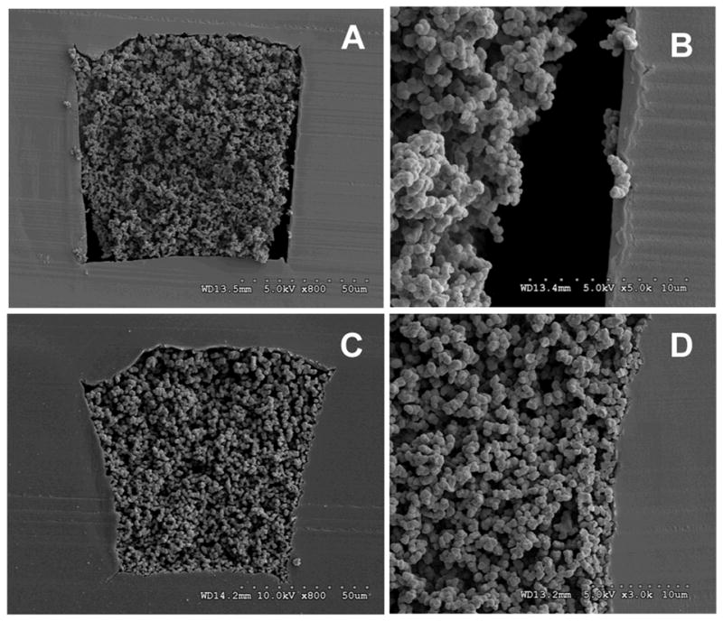
SEM images of channel cross-sections with monolith in unmodified (A, B) and photografted (C, D) channel walls.
We found necessary to custom design and manufacture a mask alignment apparatus presented in Figure 3 to achieve high-fidelity pattern transfer from the mask to the monolith. An interchangeable mask die with features defining the continuous or segmented monolith configuration was loaded into the mask bracket 2. The two-step assembly begins by loading a chip 4 containing polymerization solution onto the designated area of the base plate 5 with the ports facing downwards. Assembly is completed upon loading the XYZ stage 1 onto the designated region of the base plate. The XYZ stage (Newport Corporation, Irvine, CA) features a 3-way configuration of linear actuators that facilitates precise mask alignment over the desired region of the tee-junction. Mask alignment is performed by visual inspection through the chip viewing window in the base plate using an inverted microscope (Nikon Instruments Inc., Melville, NY) fitted with a CCD camera (QImaging, Surrey, Canada). Once mask alignment is complete the chip is transported to the UV lamp for irradiation. After irradiation, the chip is removed from the patterning assembly and flushed with several channel volumes of methanol to remove unreacted components of the original polymerization mixture.
Fig. 3.
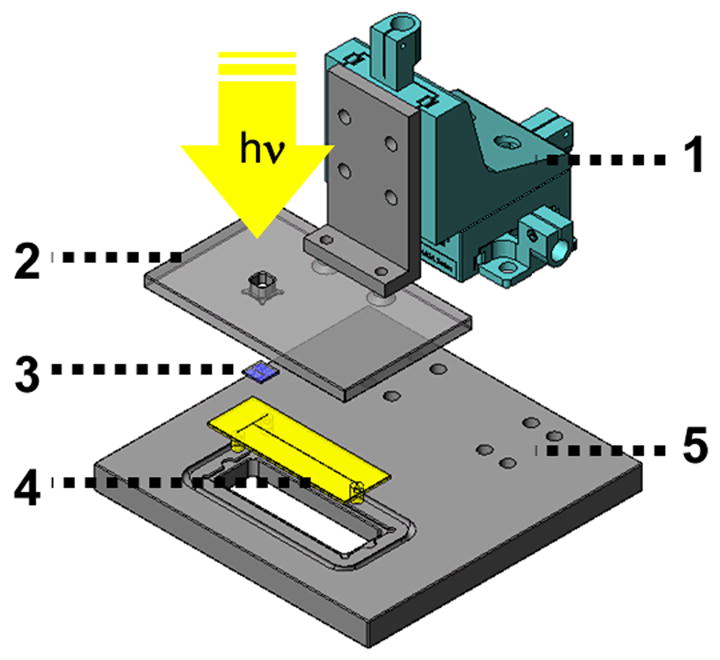
Exploded view of XYZ stage used for mask alignment to tee-junction of microfluidic chip. XYZ linear actuator driven by micrometers (1), mask bracket (2) accommodating the 1×1 cm mask die (3), chip (4), and apparatus base (5) used to anchor XYZ linear actuator.
Efficiency of mixing and reaction
The 2 mmol/L fluorescamine solution was prepared in acetone instead of water in order to minimize formation of the unreactive hydrolytic products before contact with lysine.38 The 1 mmol/L lysine solution in 0.1 mol/L sodium borate buffer, pH 8 was prepared using similar conditions that had been optimized elsewhere for high LIF signal strength.39 The lysine solution was purged with nitrogen prior to use in order to minimize fluorescence quenching by dissolved oxygen.39 These solutions were continuously infused into separate arms of the tee-junction using a syringe pump (KD Scientific Inc., Holliston, MA). The large difference in solvent viscosity between both aqueous and acetone solutions required flow rate optimization in order to maintain an equal pressure drop for each incoming stream. This optimization led to flow rates of 1.0 μL/min and 0.5 μL/min for fluorescamine and lysine solutions, respectively, and provided fluorescamine in a four-fold molar excess.
The efficiency of mixing and reaction for three channel configurations was quantitatively evaluated by LIF using an inverted fluorescence microscope. Fluorescence intensity of the reaction product was monitored at a point 1 cm away from the tee-junction using ImageJ software (NIH). The fluorescence intensities were quantified as pixel intensities from the 8-bit images and the reported intensities, performed in triplicate, were obtained by averaging the intensity profiles across the channel.
Results and discussion
Mask alignment apparatus
In addition to optimizing the composition of polymerization solution and irradiation time for improving photopatterning resolution, the design features of a custom mask aligner for precisely positioning the 100 × 200 μm aperture array on the mask die over the tee-junction of the chip proved to be critical. In particular, we found that black anodization of the aligner components illustrated in Figure 3 significantly improved the resolution by reducing the amount of reflected UV light between the base and mask bracket. Comparison of results using two different die substrates also showed the effect of UV transparency on patterning. Migrating from glass to quartz increased the exposure intensity, reduced the reaction time and improved the resolution (results not shown). Another parameter that required optimization was the aperture dimension on the quartz mask die. While the aperture length was maintained at 100 μm in order to pattern monolith plugs of the same length within the channel, the aperture width was varied from 100 μm to 1 mm. We found that longer apertures in the dark-field mask facilitate alignment of the pattern over the 100 μm wide channel within the mask whereas narrower apertures localize exposure to the region of interest and yield better defined monolith structures. Finally, we found that the fluorescent lights in the laboratory were responsible for partial polymerization of the photosensitive polymerization solution during the process of loading the chip, mask alignment under an inverted microscope station, and transfer to the UV exposure lamp. Changing the ambient light and careful design of the stations to streamline the mask alignment process effectively reduced the challenges posed by premature photoinitiation.
Effect of composition of polymerization mixture
The composition of polymerization mixture was found to have a large effect on the photopatterning resolution. Initial attempts to optimize photopatterning resolution by varying the exposure time while using polymerization mixture 1 comprising 16 wt% crosslinker, resulted in poor photopatterning resolution. An irradiation time of 10 min was required to achieve complete polymerization and resulted in poorly defined segments of monolith. Reducing the exposure time by small time increments lead to lightly crosslinked monoliths that were poorly anchored to the channel wall and subsequently flushed out of the channel during the post-polymerization rinsing steps. The unfavorable reaction kinetics of this polymerization mixture allowed for only a small window of polymerization times and limited the ability to reproduce experimental results. In order to improve both the photopatterning resolution and reproducibility the crosslinker content was increased from 16 to 28 wt% to form polymerization mixture 2 (Table 1). This mixture also provided for marked improvement in photopatterning resolution and repeatability.
As expected,46 a decrease in the median pore size from 2.6 to 1.3 μm shown in Figure 4 was observed for the polymerization mixture containing a higher percentage of crosslinker. Determining whether the improved photopatterning resolution resulted from the smaller pore size or from the reaction kinetics is difficult due to the complexity of the polymerization mixture and process of monolith formation. Upon irradiation, polymerization and crosslinking reactions are initiated and the extending network of polymer chains becomes insoluble in the porogenic mixture until complete phase separation occurs, leading to an interconnected network of pores that defines the morphology of the PPM. Increasing percentage of the crosslinker in the polymerization mixture quickly reduces the solubility of the growing polymer chains due to their much faster crosslinking and earlier phase separation from the porogens thus leading to a monolith with a smaller pore size. Satisfactory results were obtained through a limited number of experiments that were designed based on previous experience with this particular polymerization system.12
Fig. 4.
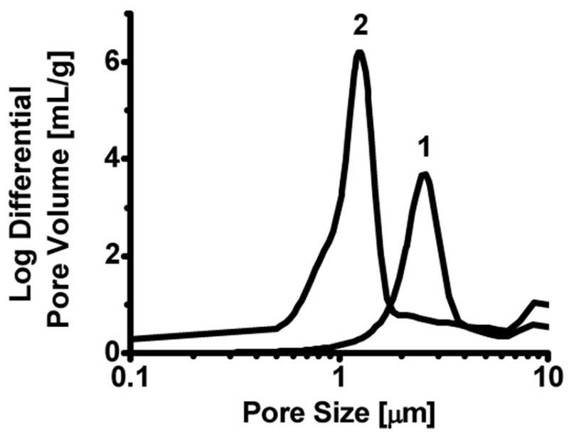
Pore size distribution of monoliths prepared from polymerization mixtures 1 and 2
Optimization of irradiation time
This optimization was performed using polymerization mixture 2. The optical micrographs of Figure 5 illustrate the sensitivity of photopatterning resolution to UV exposure time.
Fig. 5.
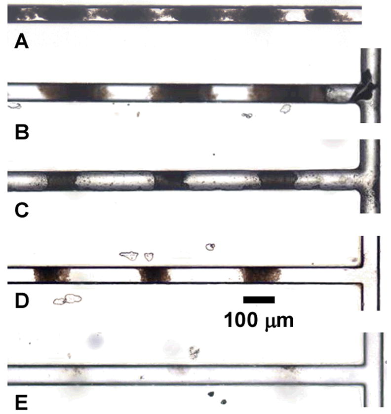
Microscope images of photopatterned porous polymer monolith in channel after 5 (A), 4.5 (B), 4.0 (C), 3.5 (D), and 3.0 min (E) UV irradiation.
As illustrated in Figure 5A, excessive exposure times resulted in a severe reduction of the open space between monolithic segments and overall poor patterning resolution. A nearly continuous 1 cm long plug of monolith is produced after 5 min of irradiation. On the other hand, short irradiation times led to poorly developed monoliths that were flushed out of the channel during the subsequent rinsing step (E). Optimal photopatterning resolution for this particular polymerization mixture was obtained after 4 and 3.5 minutes of irradiation (C and D). Closer inspection of SEM micrographs shown in Figure 6 reveals the high fidelity with which the pattern was transferred from the mask to the monolith. In particular, Figure 6B reveals the integrity of the porous structure of the 100 μm segments after rinsing, confirming a complete polymerization. Optimization of both the percentage of crosslinker in the polymerization mixture and polymerization time enabled photopatterning of porous polymer monolith in regular and well-defined 100 μm segments, the highest resolution known to date for this material.
Fig. 6.
SEM images of periodic arrangement of photopatterned porous polymer monoliths in channel cross section (A) and an individual plug demonstrating nominal 100 μm patterning resolution (B).
Lithographical factors
While the composition of the polymerization mixture and irradiation time have a significant effect on photopatterning resolution, we expected that additional contributors could be tuned for further improvement. To determine the resolution limit for patterning monoliths, we used an equation developed to predict the minimum line width that can be transferred to the photoresist coated on a silicon wafer. In the diffraction limit for contact lithography, this line width is given by Equation 1.29
| (1) |
where λ is wavelength of used light, s is the distance between the mask and the photoactive polymerization mixture in the channel, and z is the photoresist thickness. Similarity between the physical setup for patterning photoresist on a wafer and patterning polymerization mixture in a channel enables an estimation of the resolution limit for photopatterned monolith. As illustrated in Figure 7, the distance between mask and polymerization mixture in the channel s is determined by the thickness of the slide used to enclose the channels while the photoresist thickness z is analogous to the channel depth. Therefore, the theoretical limit for perfect pattern transfer using an irradiation source with output between 250 and 400 nm, a slide thickness of 0.6 mm, and a channel depth of 100 μm would be 20–25 μm. It is obvious from this approximation that we have not approached the theoretical limit and an opportunity for further improvement exists. For example, replacing the 0.6 mm slide with a 100 μm film and reducing the channel depth to 50 μm would improve the patterning resolution and reduce the theoretically achievable monolith length to 14–18 μm. Mitigating factors that challenge realization of the predicted theoretical limit include exposure to ambient light while loading the device with polymerization solution, mask alignment tolerance, optical aberrations in the plastic slide, and residual internal reflection within the patterning apparatus during exposure. To improve pattern resolution, techniques such as phase shift mask and optical proximity correction commonly used in semiconductor lithography may need to be adopted.41
Fig. 7.
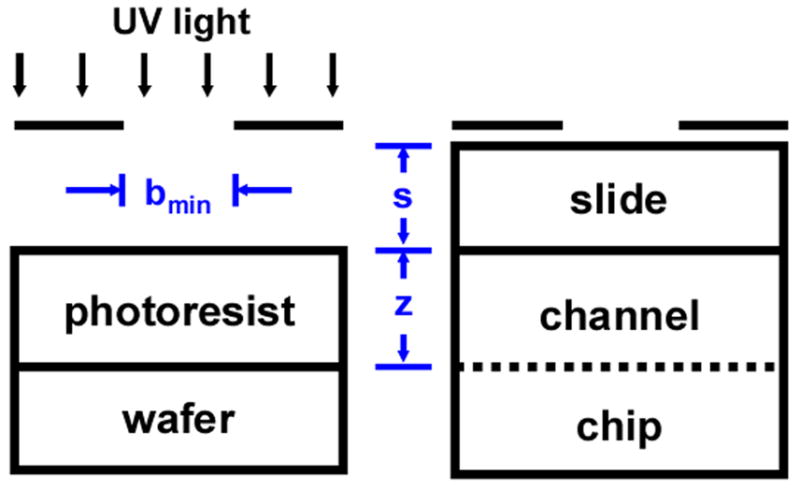
Experimental setup for patterning minimum feature size in photoresist on a silicon wafer and analogous setup for patterning monolith in a microfluidic chip
Mixing
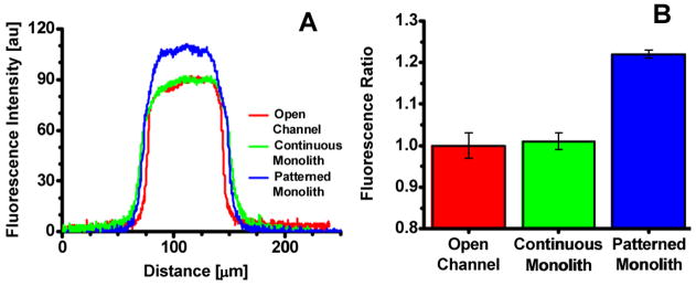
The ability to homogenously mix the contents of several streams into a single stream is an essential function required by most microfluidic applications. While a manageable task for macroscale operations, it is particularly challenging on the microscale because low Reynolds numbers and the absence of turbulence result in diffusion-limited mixing that is known to be slow.34 Examples in which mixing on the microscale is important include on-line protein derivatization,42 enzymatic digestion,43 and on chip cell lysis.44;45 To demonstrate the functional advantage of a photopatterned PPM as a passive mixer, the concentration of fluorescent reaction products was measured by LIF at a distance of 1 cm past the introduction in a tee-junction in chip with three channel configuration. The fluorescence intensity was measured across an open channel, a channel filled with a 1 cm long continuous monolithic segment and a channel with photopatterned monoliths. As shown in Figure 8A, more lysine reacted with fluorescamine when using the photopatterned monolith compared to both the open channel and continuous monolith. A fluorescence ratio for each channel configuration was calculated by dividing the average peak fluorescence intensity by that of the open channel (Figure 8B). Using this normalization technique, the amount of fluorescently labeled lysine produced after passing through a patterned monolith was 22% larger than that for an open channel. This result shows that the regularly spaced PPM plugs created by photopatterning separated by open areas are responsible for the improvement in mixing efficiency.
Fig. 8.
Fluorescence scan across channel using image software (A). Ratio of fluorescence for three channel configurations (B).
These results are qualitatively consistent with our previous work investigating the effect of pore volume on the mixing efficiency of continuous PPMs in microfluidic channels. We observed a marked improvement in mixing efficiency when the porosity of monolith was increased from 50 to 85%. This result indicated that the curtain-like structure of the polymer functioned as baffles to force flow through a meandering path that improved mixing.33 Similarly, the controlled insertion of 100μm voids between 100 μm PPM segments in this study achieved by photopatterning increases the apparent porosity of a continuous monolith from 60 to 80%. However, the serial configuration of the open voids and PPM requires a different mechanistic explanation for the observed improvement in mixing efficiency. We hypothesize that the improved mixing efficiency may also result from two more contributors: (i) an entrance effect at the beginning of each monolith segment and (ii) a split-and-recombine effect at the terminus of each monolithic segment.
Conclusions
A dual function micromixer-reactor consisting of well-defined and regularly repeating 100 μm monolithic segments was fabricated by optimizing the composition of the polymerization solution and irradiation time. Mitigating factors impairing the ability to reach the theoretical photopatterning resolution limit ways to improve current photopatterning performance were identified. Mixing-reaction performance of the photopatterned monolith was found to be 22% better than that of an empty channel and/or continuous monolith of equal length These results indicate that the open areas between 100 μm plugs of PPM are favorable for increasing the formation of reaction product and represent an important step towards achieving complex fluid control systems with a high density of monolithic valves. The photopatterning resolution demonstrated here is likely to play a critical role in current efforts to seamlessly integrate monolithic modules into multi-functional devices designed for complex chemical analyses as well as for future nodes of microfluidic development. However, we realize that the architectural novelty of this micromixer will require further investigation before any sort of substantive theory is put forth. Since the porous nature of the monolith precludes use of particle image velocimetry, we expect that efforts to elucidate the mixing mechanism will rely heavily on simulations employing computation fluid dynamics. We hope for insight gleaned from such investigations to guide mask design thus enabling fabrication of monolithic configurations with improved mixing capability.
Acknowledgments
Support for this research was provided by a grant of the National Institute of Biomedical Imaging and Bioengineering, National Institutes of Health (EB-006133). Experimental work at the Molecular Foundry was supported by the Director, Office of Science, Office of Basic Energy Sciences, Division of Materials Sciences and Engineering, of the U.S. Department of Energy under Contract No. DE-AC02-05CH11231. The authors also thank the National Center for Electron Microscopy at Lawrence Berkeley National Laboratory for use of the microtome and imaging facilities.
References
- 1.Fintschenko Y, Choi WY, Cummings EB, Fréchet JMJ, Fruetel JA, Hilder EF, Mair DA, Shepodd TJ, Svec F. Proc SPIE-Int Soc Op Eng. 2003:4982, 196–207. [Google Scholar]
- 2.Skelley AM, Scherer JR, Aubrey AD, Grover WH, Ivester RHC, Ehrenfreund P, Grunthaner FJ, Bada JL, Mathies RA. Proc Natl Acad of Sci U S A. 2005:102, 1041–1046. doi: 10.1073/pnas.0406798102. [DOI] [PMC free article] [PubMed] [Google Scholar]
- 3.Rohr T, Ogletree DF, Svec F, Fréchet JMJ. Adv Funct Mater. 2003:13, 264–270. [Google Scholar]
- 4.Rohr T, Hilder EF, Donovan JJ, Svec F, Fréchet JMJ. Macromolecules. 2003:36, 1677–1684. [Google Scholar]
- 5.Muck A, Svatos A. Talanta. 2007:74, 333–341. doi: 10.1016/j.talanta.2007.09.012. [DOI] [PubMed] [Google Scholar]
- 6.Belder D, Ludwig M. Electrophoresis. 2003:24, 3595–3606. doi: 10.1002/elps.200305498. [DOI] [PubMed] [Google Scholar]
- 7.Makamba H, Kim JH, Lim K, Park N, Hahn JH. Electrophoresis. 2003:24, 3607–3619. doi: 10.1002/elps.200305627. [DOI] [PubMed] [Google Scholar]
- 8.Peters EC, Petro M, Svec F, Fréchet JMJ. Anal Chem. 1998:70, 2288–2295. doi: 10.1021/ac9713518. [DOI] [PubMed] [Google Scholar]
- 9.Svec F, Fréchet JMJ. Science. 1996:273, 205–211. doi: 10.1126/science.273.5272.205. [DOI] [PubMed] [Google Scholar]
- 10.Ro KW, Nayalk R, Knapp DR. Electrophoresis. 2006:27, 3547–3558. doi: 10.1002/elps.200600058. [DOI] [PubMed] [Google Scholar]
- 11.Peterson DS. Lab Chip. 2005:5, 132–139. doi: 10.1039/b405311g. [DOI] [PubMed] [Google Scholar]
- 12.Levkin PA, Eeltink S, Stratton TR, Brennen R, Robotti K, Yin H, Killeen K, Svec F, Fréchet JMJ. J Chromatogr A. 2008:1200, 55–61. doi: 10.1016/j.chroma.2008.03.025. [DOI] [PMC free article] [PubMed] [Google Scholar]
- 13.Shediac R, Ngola SM, Throckmorton DJ, Anex DS, Shepodd TJ, Singh AK. J Chromatogr A. 2001:925, 251–263. doi: 10.1016/s0021-9673(01)01036-6. [DOI] [PubMed] [Google Scholar]
- 14.Ericson C, Holm J, Ericson T, Hjertén S. Anal Chem. 2000:72, 81–87. doi: 10.1021/ac990802g. [DOI] [PubMed] [Google Scholar]
- 15.Le Gac S, Carlier J, Camart JC, Cren-Olive C, Rolando C. J Chromatogr B. 2004:808, 3–14. doi: 10.1016/j.jchromb.2004.03.067. [DOI] [PubMed] [Google Scholar]
- 16.Sun XH, Yang WC, Pan T, Woolley AT. Anal Chem. 2008:80, 5126–5130. doi: 10.1021/ac800322f. [DOI] [PMC free article] [PubMed] [Google Scholar]
- 17.Peterson DS, Rohr T, Svec F, Fréchet JMJ. Anal Chem. 2002:74, 4081–4088. doi: 10.1021/ac020180q. [DOI] [PubMed] [Google Scholar]
- 18.Yu C, Davey MH, Svec F, Fréchet JMJ. Anal Chem. 2001:73, 5088–5096. doi: 10.1021/ac0106288. [DOI] [PubMed] [Google Scholar]
- 19.Yang YN, Li C, Lee KH, Craighead HG. Electrophoresis. 2005:26, 3622–3630. doi: 10.1002/elps.200410309. [DOI] [PubMed] [Google Scholar]
- 20.Yang YN, Li C, Kameoka J, Lee KH, Craighead HG. Lab Chip. 2005:5, 869–876. doi: 10.1039/b503025k. [DOI] [PubMed] [Google Scholar]
- 21.Li C, Lee KH. Analytical Biochemistry. 2004:333, 381–388. doi: 10.1016/j.ab.2004.06.007. [DOI] [PubMed] [Google Scholar]
- 22.Wen J, Guillo C, Ferrance JP, Landers JP. Anal Chem. 2007:79, 6135–6142. doi: 10.1021/ac0703698. [DOI] [PubMed] [Google Scholar]
- 23.Satterfield BC, Stern S, Caplan MR, Hukari KW, West JAA. Anal Chem. 2007:79, 6230–6235. doi: 10.1021/ac0709201. [DOI] [PubMed] [Google Scholar]
- 24.Ocvirk G, Verpoorte E, Manz A, Grasserbauer M, Widmer HM. Anal Methods Instrum. 1995:2, 74–82. [Google Scholar]
- 25.Wang XC, Yang XH, Zrang XM. Anal Sci. 2006:22, 1099–1104. [Google Scholar]
- 26.Bedair MF, Oleschuk RD. Anal Chem. 2006:78, 1130–1138. doi: 10.1021/ac0514570. [DOI] [PubMed] [Google Scholar]
- 27.Bedair M, Oleschuk RD. Analyst. 2006:131, 1316–1321. doi: 10.1039/b607359j. [DOI] [PubMed] [Google Scholar]
- 28.Koerner T, Oleschuk RD. Rapid Comm Mass Spectr. 2005:19, 3279–3286. doi: 10.1002/rcm.2181. [DOI] [PubMed] [Google Scholar]
- 29.Thompson LF, Wilson CG, Bowden MJ. Introduction to Microlithography. American Chemical Society; 1994. [Google Scholar]
- 30.Luo QZ, Mutlu S, Gianchandani YB, Svec F, Fréchet JMJ. Electrophoresis. 2003:24, 3694–3702. doi: 10.1002/elps.200305577. [DOI] [PubMed] [Google Scholar]
- 31.Yu C, Mutlu S, Selvaganapathy P, Mastrangelo CH, Svec F, Fréchet JMJ. Anal Chem. 2003:75, 1958–1961. doi: 10.1021/ac026455j. [DOI] [PubMed] [Google Scholar]
- 32.Chen GF, Svec F, Knapp DR. Lab Chip. 2008:8, 1198–1204. doi: 10.1039/b803293a. [DOI] [PubMed] [Google Scholar]
- 33.Rohr T, Yu C, Davey MH, Svec F, Fréchet JMJ. Electrophoresis. 2001:22, 3959–3967. doi: 10.1002/1522-2683(200110)22:18<3959::AID-ELPS3959>3.0.CO;2-5. [DOI] [PubMed] [Google Scholar]
- 34.Stone HA, Stroock AD, Ajdari A. Ann Rev Fluid Mech. 2004:36, 381–411. [Google Scholar]
- 35.Hatch AV, Herr AE, Throckmorton DJ, Brennan JS, Singh AK. Anal Chem. 2006:78, 4976–4984. doi: 10.1021/ac0600454. [DOI] [PubMed] [Google Scholar]
- 36.Mair DA, Rolandi M, Snauko M, Noroski R, Svec F, Fréchet JMJ. Anal Chem. 2007:79, 5097–5102. doi: 10.1021/ac070220w. [DOI] [PubMed] [Google Scholar]
- 37.Mair DA, Geiger E, Pisano AP, Fréchet JMJ, Svec F. Lab Chip. 2006:6, 1346–1354. doi: 10.1039/b605911b. [DOI] [PubMed] [Google Scholar]
- 38.Udenfrie S, Stein S, Bohlen P, Dairman W. Science. 1972:178, 871–874. doi: 10.1126/science.178.4063.871. [DOI] [PubMed] [Google Scholar]
- 39.Bantan-Polak T, Kassai M, Grant KB. Anal Biochem. 2001:297, 128–136. doi: 10.1006/abio.2001.5338. [DOI] [PubMed] [Google Scholar]
- 40.Nguyen NT, Wu ZG. J Micromech Microeng. 2005:15, R1–R16. [Google Scholar]
- 41.Levenson MD. Solid State Technol. 1995:38, 57–62. [Google Scholar]
- 42.Abonnenc M, Dayon L, Perruche B, Lion N, Girault HH. Anal Chem. 2008:80, 3372–3378. doi: 10.1021/ac800058h. [DOI] [PubMed] [Google Scholar]
- 43.Dodge A, Brunet E, Chen SL, Goulpeau J, Labas V, Vinh J, Tabeling P. Analyst. 2006:131, 1122–1128. doi: 10.1039/b606394b. [DOI] [PubMed] [Google Scholar]
- 44.Irimia D, Tompkins RG, Toner M. Anal Chem. 2004:76, 6137–6143. doi: 10.1021/ac0497508. [DOI] [PubMed] [Google Scholar]
- 45.Lee CY, Lee GB, Lin JL, Huang FC, Liao CS. J Micromech Microeng. 2005:15, 1215–1223. [Google Scholar]
- 46.Viklund C, Svec F, Fréchet JMJ, Irgum K. Chem Mater. 1996:8, 744–750. [Google Scholar]


