Abstract
Purpose: To assess 3-dimensional (3D) pulsatile displacement forces (DF) acting on thoracic endografts using 3D computational techniques.
Methods: A novel computational method to quantitate the pulsatile 3D flow and pressure fields and aortic wall dynamics in patient-specific anatomical models based on cardiac-gated computed tomography (CT) scans was used to construct simulations of the proximal and mid-descending thoracic aorta. Endografts of varying lengths and diameters were implanted in these patient-specific models. The magnitude and direction of the DF vector were calculated and expressed in Newtons (N). This DF included the effects of both the pressure and shearing stresses of blood.
Results: The magnitude of DF increased with endografts of increasing diameter and length. A 36-mm endograft in the mid-descending aorta had a mean DF of 21.7 N with a peak systolic DF of 27.8 N and an end-diastolic DF of 16.7 N. Conversely, a 30-mm endograft in the proximal descending aorta had a mean DF of 14.9 N, with peak systolic and end-diastolic DFs of 18.9 and 11.5, respectively. The orientation of the DF acting on the endograft varied depending on aortic angulation and tortuosity; in general, the vector was perpendicular to the greater curvature of the endograft rather than along the downstream longitudinal centerline axis of the aorta as is commonly believed. The DF vector pointed primarily in the cranial direction for the proximal descending endograft and in the sideways direction for the mid-descending endograft simulation. Furthermore, it was shown that elevated pressure plays an important role in the magnitude and direction of DF; an increase in mean blood pressure resulted in an approximately linearly proportional increase in DF.
Conclusion: The orientation of the DF varies depending on curvature and location of the endograft, but in all instances, it is in the cranial rather than caudal direction on axial imaging. This is counter to the intuitive notion that displacement forces act in the downward direction of blood flow. Therefore, we postulate that migration of thoracic endografts may be different from abdominal endografts since it may involve upward rather than downward movement of the graft. Computational methods can enhance the understanding of the magnitude and orientation of the loads experienced in vivo by thoracic aortic endografts and therefore improve their design and performance.
Keywords: displacement forces, aortic endografts, endograft migration, thoracic aortic aneurysm, angulation and curvature, computational fluid dynamics
Endovascular treatment for thoracic aortic disease has developed significantly in the last 15 years. The pioneering work of Dake and colleagues1,2 began in the mid-90s; now, tens of thousands of procedures are performed yearly in the US alone.3 Thoracic aneurysms and aortic dissections constitute the majority of clinical cases. Although the short- and midterm outcomes of endovascular procedures have been favorable compared to open surgical repair, the risks of aneurysm enlargement, endoleaks, endograft collapse, and migration demand costly periodic screenings of the patient.4 Moreover, a number of investigators have expressed concern regarding the long-term durability and outcomes following thoracic endografting.4–7
The unique anatomical and biomechanical environment of the thoracic aorta (i.e., large motion, highly pulsatile flow) poses significant challenges to the long-term success of endografts. A deeper understanding of the forces experienced by endografts in vivo is required to improve their performance and long-term durability. While the displacement force (DF) acting on aortic endografts has been assumed to be in the downward direction of blood flow, recent studies in the abdominal aorta have shown that sideways displacement of endografts in the aneurysm sac is a predictor of late adverse events.8,9 In-vitro experimental studies,10,11 as well as theoretical and computational studies,12 have been conducted to investigate the magnitude of loads acting on thoracic endografts, their resistance to dislodgment, as well as their stability and movement. However, in all cases, the studies failed to either reproduce the complex anatomical configuration of the aorta and endograft or the highly pulsatile blood flow, pressure, and wall dynamics of the thoracic aorta. The purpose of this investigation is to study the magnitude and direction of pulsatile displacement forces acting on realistic models of thoracic aortic endografts built from image data using computational fluid dynamics (CFD) techniques. We investigate the impact that different factors, such as device location, size, and elevated pressure, have on the forces experienced by the endograft.
METHOD
Model Design
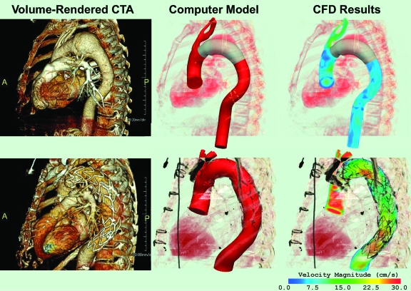
Three-dimensional (3D) computer models of thoracic aortic aneurysms (TAA) were constructed using de-identified cardiac-gated computed tomographic angiography (CTA) data. The models represented aneurysms located in the proximal and mid-descending thoracic aorta, respectively, and included data from the ascending thoracic aorta, aortic arch, descending thoracic aorta, brachiocephalic trunk, left common carotid artery, and left subclavian artery (Fig. 1).13 Once the computer models were created, CFD analyses were performed to simulate blood flow, blood pressure, and vessel wall dynamics using techniques developed by our group.14–17 These tools enable the representation of realistic pulsatile flow waves, heart rate, arterial pressure, and vessel wall and endograft mechanical properties. The magnitude and direction of time-varying displacement forces (DF), expressed in Newtons (N), exerted by the blood flow on the endografts were then calculated by integrating the distribution of tractions (pressure and the shearing stresses of blood) acting on the surface of the devices. In this analysis, the impact of device location, size, and elevated pressure on the forces experienced by the device were examined.
Figure 1.
♦ Computer methodology: 3D computer models (center) of the thoracic aorta were built based on the CTA datasets (left). The CFD analyses (right) show a volume-rendering of the blood velocity for the preoperative model of the proximal descending TAA with a virtually-implanted endograft (above) and the postoperative model of a descending TAA after treatment with an endograft (below)
For the simulations, the model of the proximal descending TAA, which corresponded to a preoperative configuration, was modified by virtually implanting a 30-mm endograft of adequate length; 10% graft oversizing was assumed. Using this approach, the range of loads experienced by the device “a priori” could be measured. The model of the mid-descending TAA was created with a 36-mm endograft in place; the stent-graft was approximately twice the length of the virtual endograft in the proximal descending TAA model. Thus, the postoperative mid-descending TAA model corresponded to an actual postoperative scan (Fig. 1).
Hemodynamic Variables
The variables defining the hemodynamic state used in the CFD analyses for both the proximal descending and mid-descending TAA models were typical values for volumetric flow and pressure for the ascending thoracic aorta.18 The mean flow and heart rate were 4.9 L/min and 67 bpm, respectively. The aortic systolic, diastolic, and mean pressures were 145, 85, and 111 mmHg, respectively.
RESULTS
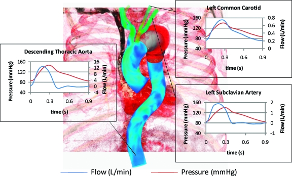
Figure 2 shows the pressure and flow waveforms of the descending thoracic aorta, left subclavian artery, and left common carotid artery obtained in the CFD simulations for both models. Individual branch flow waveforms varied depending on outflow boundary conditions of each vessel.15 The differences between the descending thoracic aorta and common carotid artery flow waveforms are shown with forward flow in the carotid artery throughout the cardiac cycle and reversed flow in the descending aorta during diastole, which represent normal physiological variations. Figure 3 illustrates how the contribution of the pressure to the total load experienced by the device was several orders of magnitude larger than the wall shear stress contribution.
Figure 2.
♦ Flow and pressure waveforms in selected vessels obtained in the CFD analysis of both the proximal descending and mid-descending TAA models
Figure 3.
♦ Wall shear (A) and pressure (B) stresses representing the actions of the blood on the endograft. These stresses are integrated over the surface of the endograft to calculate the total 3D force exerted by the pulsatile flow
Preoperative Proximal Descending TAA Model
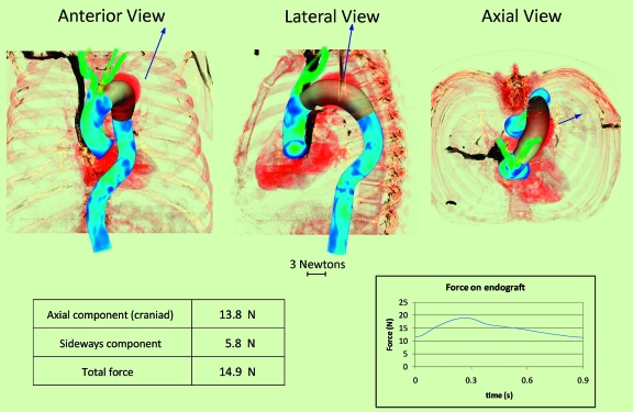
After completing this simulation with a virtually implanted 30-mm endograft, the total DF was calculated; the magnitude and orientation of this force acting on the endograft in the anteroposterior (AP), lateral, and axial projections are represented by the size and direction of the arrows in Figure 4. The DF vector has a mean value of 14.9 N, with peak systolic and end-diastolic values of 18.9 and 11.5 N, respectively. Note that the axial orientation of the DF is in the cranial direction rather than in the caudal direction. The mean of the DF in the cranial direction is 13.8 N, whereas the mean in the sideways direction is 5.8 N. The displacement vector appears to be largely determined by the curvature of the endograft.
Figure 4.
♦ Proximal descending thoracic aortic endograft in anterior, lateral, and axial views showing the vector (arrow) of the displacement force (DF). Mean value of the DF vector, its sideways and axial components, and temporal variation over the cardiac cycle are given below. Note that the axial DF vector is in the cranial rather than the caudal direction. The displacement force magnitude changes over the cardiac cycle, varying from 11.5 N in diastole to 18.9 N at peak systole
Postoperative Mid-Descending TAA Model
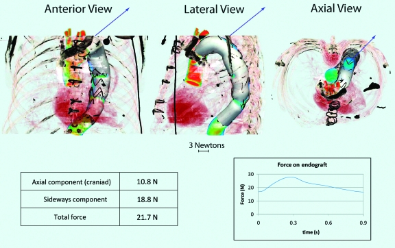
After completing the CFD analysis of the postoperative mid-descending TAA model with a 36-mm endograft in place, calculation of the DF produced a vector with larger mean (21.7 N), peak systolic (27.8 N), and end-diastolic (16.7 N) values than the preoperative model scenario. This was due to the larger size of the device, since the hemodynamic conditions (see pressure and flow waveform, Figure 2) were identical to those in the preoperative model. The displacement vector (Fig. 5) appears to be largely determined by the curvature of the endograft. Contrary to the preoperative scenario, the DF vector pointed primarily in the sideways direction with a mean value of 18.8 N, due to the longer length of the device and its more distal location. Conversely, the axial component was now smaller (mean 10.8 N). Again, note that axial orientation of the DF was in the cranial direction rather than the caudal direction.
Figure 5.
♦ Mid-descending thoracic aortic endograft in anterior, lateral, and axial views showing the vector (arrow) of the displacement force (DF). Mean value of the DF vector, its sideways and axial components, and temporal variation over the cardiac cycle are given below. Note that the axial displacement force vector is in the cranial rather than the caudal direction. The displacement force magnitude changes over the cardiac cycle, varying from 16.7 N in diastole and 27.8 N at peak systole
Effects of Increased Pressure on the DF of the Mid-Descending Thoracic Aortic Endograft
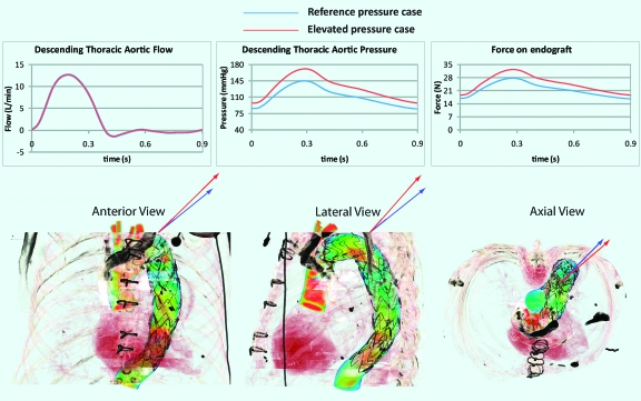
Figure 6 shows the flow and pressure waveforms considered in this analysis, as well as the waveforms used in the initial simulation. The flow waves remained unchanged. The elevated pressure waveform had a mean value of 130 mmHg, with a systolic peak of 171 mmHg, a diastolic minimum of 97 mmHg, and a pulse pressure of 74 mmHg, while in the previous model, the mean pressure was 111 mmHg, with a systolic peak of 145 mmHg, a diastolic minimum of 85 mmHg, and a pulse pressure of 60 mmHg. Thus, the mean pressure in the elevated simulation was 16.5% larger than the pressure in the initial scenario. The DF vector had larger mean (25 N), peak systolic (32.5 N), and diastolic (22.6 N) values than the initial simulation (see graph in Figure 6), indicating that the increase in mean DF was approximately linearly proportional to the increase in mean pressure over this range of pressure.
Figure 6.
♦ Flow and pressure waves with pulsatile DF for the reference pressure (blue plots) and the elevated pressure (red plots) simulations. The images below compare the orientation of the DF vectors for the reference pressure (blue arrows) and the elevated pressure (red arrows) scenarios in the anterior, lateral, and axial views
The increase in pulse pressure resulted in a significant change in the orientation of the DF vector. The Table compares the axial (craniad) and sideways components of the reference pressure scenario to the values for the elevated pressure simulation. The greatest increase was in the axial component (37%), whereas the increase in the sideways component was only 7%, which can be explained by the increased acceleration of blood due to the 14 mmHg higher pulse pressure. The blood was therefore pushed against the outer curve of the graft more vigorously than before, which resulted in the larger craniad component of the DF vector.
TABLE.
Axial Component, Sideways Component, and Total Mean Displacement Force for the Reference Pressure and Elevated Pressure Scenarios
DISCUSSION
It has long been assumed that endograft migration is due to downstream displacement by the action of flowing blood. A number of experimental and computational studies in endografts for both AAA and TAA have been based on this presumption.10,19–21 However, we have shown that in the case of abdominal aortic endografts this assumption is not true; the largest component of the endograft displacement force is in the sideways, rather than downstream (caudal), direction.8,9
In the current analysis, we have extended our studies to the thoracic aorta. The main finding of these experiments is that the primary orientation of the DF vector acting on thoracic aortic endografts is not in the downward (caudal) direction, but rather in the upward direction (craniad) with respect to blood flow. Due to the curvature of the aortic arch and descending thoracic aorta, this vector also has an important sideways component relative to the direction of blood flow. The thoracic aortic curvature is very large, and blood flow changes from the cranial direction in the ascending aorta to the caudal direction in the descending aorta. This factor is of critical importance and has not heretofore been considered in the area of thoracic endografting and stability of implanted devices. In general, the more proximal the endograft is implanted, the greater the craniad component of displacement. The prevailing view that the orientation of DF is primarily in the downstream direction of blood flow was based on the assumption that the main contributor to the DF is the shearing force exerted by blood flow on the endograft. In this study, we showed just the opposite: the combination of the blood pressure and the geometry of the endograft are much more important determinants of the magnitude and direction of DF. This finding has profound implications on the design of thoracic endografts. Fixation systems must be able to secure the thoracic devices in place, withstanding the forces applied to them. Thoracic endografts may be much more unstable than previously suspected, particularly in the arch and proximal descending thoracic aorta. Thoracic endograft migration may be more difficult to evaluate due to the imaging challenges of the thoracic aorta. It is also possible that thoracic endograft migration has been overlooked since most studies on migration have looked for downward (in the direction of blood flow) displacement of endografts, rather than craniad or sideways displacement.
Computational methods are required to gain a better understanding of the magnitude and orientation of the loads experienced by thoracic aortic endografts in vivo, since they allow us to consider complex geometries and flow and pressure states. Understanding the loads experienced by endografts can improve their design and performance. Displacement force analysis is complex and requires accurate 3D geometric models and CFD computations under physiological flows and pressures.
The analysis presented here is just a first step and needs to be expanded to investigate the effects of several factors that may influence the magnitude and direction of DF. We have assumed that pressure in the TAA sac after endograft deployment is zero, which is not the case in patients who have endoleaks after endovascular aneurysm repair. Furthermore, it should be noted that the results have been obtained under the assumption that both the arterial and graft walls are rigid. Future work will include the compliance of the walls and an evaluation of how much this compliance might affect the forces experienced by grafts. Additional factors that may influence the magnitude and direction of DF are heart rate, aneurysm size, vessel wall and endograft compliance, and exercise. Clinical correlation and in-vivo/in-vitro experimental studies are needed to complement this computational approach. Thus, it is imperative to investigate factors that counteract the DF to keep the device in place. Some of these factors are: friction developed at the fixation points between the graft and the wall, fixation length, longitudinal columnar force, and the influence of penetrating hooks and barbs.
Conclusion
This is the first geometrically realistic 3D description of pulsatile displacement forces acting on thoracic aortic endografts. The primary orientation of the displacement force vector acting on an endograft implanted in a TAA is not in the downward (caudal) direction, but rather in the upward direction (craniad) with respect to blood flow on axial views. This vector also has an important sideways component in the direction relative to blood flow due to the curvature of the aortic arch and descending thoracic aorta. In general, the more proximal the endograft is implanted, the greater the craniad component of displacement. Three-dimensional computational analysis may provide a powerful tool to evaluate the risk of endograft migration in vivo.
Footnotes
The annual ISES Endovascular Research Competition held on February 9, 2009, at International Congress XXII on Endovascular Interventions (Scottsdale, Arizona, USA) evaluated participants on both their oral and written presentations. ISES congratulates the 2009 winners.
This study was supported by the National Institutes of Health/NHLBI grant 2R01 HL64327-05A1. In accordance with the NIH Public Access Policy, this article is available for open access at PubMed Central.
The authors have no commercial, proprietary, or financial interest in any products or companies described in this article.
REFERENCES
- Dake M.D., Miller D.C., Semba C.P. et al. Transluminal placement of endovascular stent-grafts for the treatment of descending thoracic aortic aneurysms. N Engl J Med. 1994;331:1729–1734. doi: 10.1056/NEJM199412293312601. [DOI] [PubMed] [Google Scholar]
- Dake M.D., Miller D.C., Mitchell R.S. et al. The “first generation” of endovascular stent-grafts for patients with aneurysms of the descending thoracic aorta. J Thorac Cardiovasc Surg. 1998;116:689–704. doi: 10.1016/S0022-5223(98)00455-3. [DOI] [PubMed] [Google Scholar]
- Abul-Khoudoud O., Criado F.J. A decade of thoracic endografting: planning the next 10 years…. J Endovasc Ther. 2004;11(Suppl II):II-72–II-81. doi: 10.1177/15266028040110S613. [DOI] [PubMed] [Google Scholar]
- Matsumura J.S., Cambria R.P., Dake M.D. et al. International controlled clinical trial of thoracic endovascular aneurysm repair with the Zenith TX2 endovascular graft: 1-year results. J Vasc Surg. 2008;47:247–257. doi: 10.1016/j.jvs.2007.10.032. [DOI] [PubMed] [Google Scholar]
- Leurs L.J., Bell R., Degrieck Y. et al. Endovascular treatment of thoracic aortic diseases: combined experience from the EUROSTAR and United Kingdom Thoracic Endograft registries. J Vasc Surg. 2004;40:670–680. doi: 10.1016/j.jvs.2004.07.008. [DOI] [PubMed] [Google Scholar]
- Ricco J.B., Cau J., Marchand C. et al. Stent-graft repair for thoracic aortic disease: results of an independent nationwide study in France from 1999 to 2001. J Thorac Cardiovasc Surg. 2006;131:131–137. doi: 10.1016/j.jtcvs.2005.07.029. [DOI] [PubMed] [Google Scholar]
- Bavaria J.E., Appoo J.J., Makaroun M.S. et al. Endovascular stent grafting versus open surgical repair of descending thoracic aortic aneurysms in low-risk patients: a multicenter comparative trial. J Thorac Cardiovasc Surg. 2007;133:369–377. doi: 10.1016/j.jtcvs.2006.07.040. [DOI] [PubMed] [Google Scholar]
- Rafii B.Y., Abilez O.J., Benharash P. et al. Lateral movement of endografts within the aneurysm sac is an indicator of stent-graft instability. J Endovasc Ther. 2008;15:335–343. doi: 10.1583/08-2422.1. [DOI] [PubMed] [Google Scholar]
- Figueroa C.A., Taylor C.A., Yeh V. et al. Effect of curvature on displacement forces acting on aortic endografts: a 3-dimensional computational analysis. J Endovasc Ther. 2009;16:284–294. doi: 10.1583/08-2667.1. [DOI] [PMC free article] [PubMed] [Google Scholar]
- Veerapen R., Dorandeu A., Serre I. et al. Improvement in proximal aortic endograft fixation: an experimental study using different stent-grafts in human cadaveric aortas. J Endovasc Ther. 2003;10:1101–1109. doi: 10.1177/152660280301000613. [DOI] [PubMed] [Google Scholar]
- Liffman K., Sutalo I.D., Lawrence-Brown M.M. et al. Movement and dislocation of modular stent-grafts due to pulsatile flow and the pressure difference between the stent-graft and the aneurysm sac. J Endovasc Ther. 2006;13:51–61. doi: 10.1583/05-1699.1. [DOI] [PubMed] [Google Scholar]
- Lam S., Fung G., Cheng S. et al. A computational study on the biomechanical factors related to stent-graft models in the thoracic aorta. Med Biol Eng Comput. 2008;46:1129–1138. doi: 10.1007/s11517-008-0361-8. [DOI] [PubMed] [Google Scholar]
- Wilson N.M., Wang K.C., Dutton R.W. Lecture Notes in Computer Science. vol. 2208. 2001. A software framework for creating patient specific geometric models from medical imaging data for simulation based medical planning of vascular surgery; pp. 449–456. Berlin Springer. [Google Scholar]
- Taylor C.A., Hughes T.J.R., Zarins C.K. Finite element modeling of blood flow in arteries. Comput Meth Appl Mech Eng. 1998;158:155–196. [Google Scholar]
- Vignon-Clementel I.E., Figueroa C.A., Jansen K.E. et al. Outflow boundary conditions for three-dimensional finite element modeling of blood flow and pressure in arteries. Comput Meth Appl Mech Eng. 2006;195:3776–3796. [Google Scholar]
- Figueroa C.A., Vignon-Clementel I.E., Jansen K.E. et al. A coupled momentum method for modeling blood flow in three-dimensional deformable arteries. Comput Meth Appl Mech Eng. 2006;195:5685–5706. [Google Scholar]
- Kim H.J., Figueroa C.A., Hughes T.J. et al. Augmented Lagrangian method for constraining the shape of velocity profiles at outlet boundaries for three-dimensional finite element simulations of blood flow. Comput Meth Appl Mech Eng. 2009 in press (DOI:10.1016/j.cma.2009.02.012) [Google Scholar]
- Nichols W.W., O'Rourke M.F. McDonald's Blood Flow in Arteries: Theoretical, Experimental and Clinical Principles, 5th ed. 2005. London Hodder Arnold. [Google Scholar]
- Resch T., Malina M., Lindblad B. et al. The impact of stent design on proximal stent-graft fixation in the abdominal aorta: an experimental study. Eur J Vasc Endovasc Surg. 2000;20:190–195. doi: 10.1053/ejvs.1999.0991. [DOI] [PubMed] [Google Scholar]
- Zarins C.K. Stent-graft migration: how do we know when we have it and what is its significance? [commentary] J Endovasc Ther. 2004;11:364–365. doi: 10.1583/03-1142C.1. [DOI] [PubMed] [Google Scholar]
- Li Z., Kleinstreuer C., Farber M. Computational analysis of biomechanical contributors to possible endovascular graft failure. Biomech Model Mechanobiol. 2005;4:221–234. doi: 10.1007/s10237-005-0003-0. [DOI] [PubMed] [Google Scholar]


