Abstract
The most common form of optoacoustic generation is thermoelasticity. Thermoelastic transduction is easy to implement and can be very broadband. However, its major drawback has always been poor conversion efficiency when a metallic film is used as the transducer. We have investigated two alternate structures for high efficiency, one based on a thin polymer film and the other using a two-dimensional nanostructure.
1 Introduction
Ultrasound is an attractive modality for minimally invasive microscopy. Although piezoelectric technology is mature for arrays operating at less than 10 MHz, it is extremely difficult to produce 2-D arrays operating above 20 MHz due to dicing, cross-talk, and interconnect limitations. In vivo 3-D imaging at sufficiently high frame rate and spatial resolution for clinical applications requires 2-D arrays operating at frequencies higher than 50 MHz, a huge challenge for piezoelectric technology.
A promising alternative uses optical generation and detection of ultrasound (i.e., optoacoustics). Two laser beams, one for generation and the other for detection, probe these structures. Simple optics and scanning systems enable element size and spacing of several microns. Optoacoustics overcomes some major difficulties of piezoelectrics, specifically eliminating dicing and all electrical connections.
The most common form of optoacoustic generation is thermoelasticity. Thermoelastic transduction is easy to implement and can be very broadband. However, its major drawback has been poor conversion efficiency when a metallic film forms the transducer. Here we present two high efficiency structures, one using a thin polymer film and the other a two-dimensional nanostructure.
2 Polymer film optoacoustic transducer
Sound can be generated thermoelastically by focusing a laser pulse onto a light-absorbing film deposited on a transparent substrate [1,2]. Absorption rapidly heats a small volume, which expands and launches an acoustic wave into the overlying sample. Theoretically, an ideal thermoelastic source produces a temporal acoustic profile proportional to the time derivative of the input optical pulse [3,4]. Thus, thermoelastic generation can be very broadband with an appropriate input laser source.
In previous work, we have shown that thermoelastic conversion efficiency can be improved by 20 dB compared to a thin film metal absorber using an optical absorbing film consisting of a mixture of polydimethylsiloxane (PDMS) and carbon black spin-coated onto a glass substrate [3,5,6]. The optical absorption depth of the black PDMS film was estimated to be about 1 μm [3]. However, the film is about 25 μm thick [5], which means that more than 20 μm of the overlying film doesn’t contribute to the source at all, but simply attenuates ultrasound, especially at frequencies higher than 50 MHz. Below we show that we have reduced the film thickness from 25 μm to nearly 11 μm, improving thermoelastic conversion efficiency, as well as the center frequency and bandwidth of the device.
The polymer PDMS is a transparent silicone, so an absorber must be added. Our old 25 μm thick sample is a mixture of PDMS, toluene, and carbon black (25 nm particle size, low structure; Raven 2500 Ultra, Columbian Chemicals Inc.) spin-coated onto a glass substrate at 2000 rpm for 2 minutes. To make a thinner black PDMS film, dispersion of carbon black into PDMS must be significantly improved, thus producing a uniform film at higher spin-coating speeds. Carbon black with larger particle size and high structure (increasing oil absorption) enhances dispersion. Although toluene decreases the viscosity, we also observed that it actually prevents carbon black from dispersing into PDMS. So our new sample is a mixture of only PDMS and carbon black (45 nm particle size, high-structure; Raven 14, Columbian Chemicals Inc.) with a ratio of 6 : 1. The mixture is spin-coated (WS-400A-6NPP/LITE, Laurell Technologies Corp.) at 5000 rpm for 2 minutes, and then cured at 100 degrees for an hour. The film thickness is 11 μm as measured with a surface profiler (Alpha Step 500 Profilometer, KLA Tencor Inc.).
The black PDMS film was mounted on a sample holder at the water surface of a small water tank to measure optoacoustic transduction efficiency. A laser pulse was focused onto the film through a glass substrate. A commercial high energy solid state laser (Surelite, Continuum, Inc.) producing a 5 ns laser pulse with energy of 200 mJ (λ = 1064 nm) was used. We coupled the laser beam into a multimode fiber with core size of 200 μm, and output it through a collimator (11 mm focal length; F220SMA-B, Thorlabs Inc.); this reduces pulse energy to about 500 μJ. Before focusing the pulse onto the film, it goes through a set of neutral density filters (optical density = 3.0), further reducing the energy to about 500 nJ. Ultrasound was detected by a spherically focused transducer sealed at the bottom of the water tank by two ‘O’ rings. An f/1.4, LiNbO3 transducer (Resource Center for Medical Ultrasonic Transducer Technology, University of Southern California) with a focal length of 4.1 mm and a center frequency of 80 MHz was used to record the acoustic signal. The thermoelastic source was placed 4.1 mm from the transducer (i.e., at the focal length of the transducer). The detected signal was amplified by 30 dB (5910R, Panametrics Inc.) before data collection.
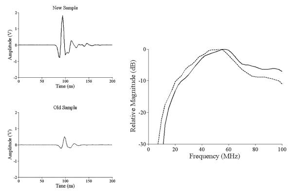
Figure 1 shows the detected signal, averaged 1000 times, from new and old films. The new thin film is 11 dB more efficient than the older thick film. Corresponding spectra (each has been normalized to its own peak) are also presented in this figure. They confirm that higher frequency components are attenuated more in the black PDMS film. The center frequency of the generated ultrasound is 60 MHz, with a –6 dB bandwidth of 80%.
Fig. 1.
With a 5 ns laser pulse, signals from new 11 μm black PDMS film and old 25 μm PDMS film. Spectral comparison of the new film (solid curve) and the old film (dashed curve). Magnitude is relative to spectral peak of each signal separately.
In addition to the improved transduction efficiency and center frequency of the new film, the acoustic power produced on each optical excitation is also critical for high-frequency real-time imaging at high signal to noise ratio (SNR). High SNR per pulse can eliminate all signal averaging, an important consideration for real-time imaging. As an initial test of the ultimate power possible, the optical power per pulse was increased from the 500 nJ used to create the signal presented above. Up to a pulse power of 50 μJ, the acoustic signal increased linearly with optical power (i.e., the 50 μJ signal was 40 dB larger than the 500 nJ one). Above 50 μJ, acoustic power no longer increased linearly with optical power, and the film was thermally damaged at a threshold of about 150 μJ.
With an optical power of 50 μJ delivered to an optical spot size of 25 μm, the acoustic pressure is estimated to be about 800 kPa at a distance of 10 mm. Using a simple diffraction model from a 25 μm diameter source, the acoustic pressure at the film is estimated to be about 600 MPa, a value more than sufficient for applications in real-time acoustic microscopy. We also note that at these power levels the transduction efficiency increases significantly. Efficiency is defined as the acoustic power, calculated from the acoustic pressure estimated above, divided by the input optical power. At the low powers reported previously, the transduction efficiency was about 10−6 [6]. Here, the efficiency is about 1.7%.
3 Two-dimensional nanostructure optoacoustic transducer
The optical absorption depth, estimated to be about 1 μm from the substrate for the black PDMS film, defines the size of the acoustic source. Thus, the remaining film simply attenuates the generated ultrasound, especially high frequency components, by about 1 dB/μm [4]. This limits bandwidth. With carbon black as the optical absorber, the film thickness cannot be reduced further with current spin-coat technology because the carbon black-PDMS mixture is very viscous. This motivated us to consider other absorbing structures with reduced film thickness to further improve bandwidth.
Gold nanoparticles have been known as efficient optical absorbers because surface plasmons localized around the particles strongly absorb light at a resonant wavelength depending on their size, shape, and local dielectric environment [7]. We have fabricated a novel optoacoustic generation structure consisting of a 2-D gold nanoparticle array sandwiched between a transparent substrate and a 4.5 μm thick PDMS layer.
The first and key step is to fabricate SiO2 stamps, which consist of 1D 200 nm thick SiO2 patterns on a Si wafer. Laser interference lithography (LIL) [8,9] was performed on a Si wafer with 200 nm thick SiO2, 10 nm thick Cr and 90 nm thick photoresist (PR) on top. The He-Cd laser has a wavelength of 325 nm with power of 50 mW. The periodic line grating patterns were obtained through the laser interference between the direct beam and the reflected beam from the mirror.
The next step is to fabricate a 2D nano-square array mold using an A90A scheme with the LIL-produced 1D grating. The mold consists of 2D arrangements of SiO2 pillars, with height of 200 nm and period of 220 nm, on top of a Si wafer. It is then imprinted on a 200 nm thick polymer layer spin-coated onto a glass substrate, producing a 200 nm thick polymer layer with 2-D arrangements of air holes spaced every 220 nm. Each hole is 200 nm high and 128 nm by 110 nm in cross section. A 20 nm layer of gold is deposited on top of the polymer structure using an electron beam evaporator. Liftoff was then performed by soaking the sample in acetone within a low-power ultrasonic bath, removing the polymer layer, as well as the overlying gold layer. A mixture of PDMS and toluene, with a ratio of 2 : 1, is then spin-coated into a 4.5 μm thick layer on top of the gold nanoparticle layer.
To measure the optoacoustic transduction efficiency of the gold nanostructure, it was mounted on a sample holder at the water surface of a small water tank using a setup almost identical to that described in the previous section. The excitation wavelength is tuned to 700 nm, about the resonance wavelength as determined in transmission measurements, and a pulse energy of 100 nJ was used.
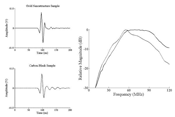
Figure 2 shows the detected signal, averaged 1000 times, from the gold nanostructure film. In comparison, the detected signal from the black PDMS film, also averaged 1000 times, is presented in the same figure. The acoustic signal from the gold nanostructure film is larger than that from the black PDMS film despite the fact that the gold nanostructure film is not able to absorb 100% of the optical energy as the black PDMS film does. This can be attributed to the reduced thickness of the gold nanostructure film, which means less attenuation to generated acoustic waves.
Fig. 2.
Signals from a 4.5 μm film with a single layer of gold nanoparticles and an 11 μm black PDMS film. Spectral comparison of the gold nanostructure film (solid curve) and the black PDMS film (dashed curve).
Corresponding spectra (each normalized to its own peak) are shown on the right side of the same figure. The reduced thickness has an even bigger impact on the signal spectrum. The spectrum from the gold nanostructure shows significant improvement at frequencies above 50 MHz. This also reconfirms that higher frequency components are attenuated more in the PDMS layer overlying the acoustic source.
The acoustic signal should be a linear function of the absorbed energy, and the absorption of the gold nanostructure film depends on the incident wavelength; thus, the acoustic amplitude should change with wavelength similar to the optical absorption spectrum. We were able to sweep the incident wavelength from 675 nm to 1000 nm with our laser system. For the black PDMS film, the output amplitude does not change significantly with wavelength, which is expected because the film is 100% absorbing over this wavelength range. For the gold nanostructure film, the maximum output is located near 700 nm, while the minimum output is near 1000 nm, which agrees fairly well with optical transmission measurements. The corresponding amplitudes have a ratio of 7.5 : 1.
4 Integrated transmit/receive optoacoustic transducer
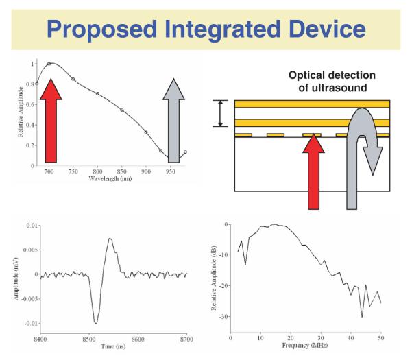
The unique optical properties of the gold nanostructure provide a possible method to integrate it directly with detection arrays, specifically a very thin polymer etalon [10], where the detection wavelength is tuned to the minimum absorption wavelength of the gold nanostructure film. The gold nanostructure, working as an optoacoustic transmitter, has a very high extinction ratio, meaning that at resonance wavelength, most optical energy is absorbed by the structure, while far from the resonance wavelength, most energy is transmitted through the structure. Thus, we can fabricate the etalon on top of the gold nanostructure, as illustrated in the top right of figure 3. Clearly, most of the laser energy at the maximum absorption wavelength is transduced into ultrasound, whereas most of the laser energy at minimum absorption is transmitted for detection. Ideally, the structure would absorb 100% of the generation beam and transmit 100% of the detection beam. A structure with optical absorption close to ideal might be achieved by optimizing the gold nanoparticle’s size, spacing, and shape.
Fig. 3.
Schematic of a proposed integrated optoacoustic transmit/receive device. First recorded pulse-echo waveform from such a structure is presented on the bottom.
As an initial test of this concept, we have fabricated an integrated device, with an etalon on top of the gold nanostructure. The thickness of the etalon bulk is 5.9 μm. A simple pulse-echo experiment was performed using an infinite plane as the reflecting object. A laser pulse at the resonance wavelength with duration of 6 ns was focused to a 400 μm spot on the gold nanostructure. Ultrasound launched into the overlying water was reflected from a glass slide, placed about 6 mm from the etalon surface. The detection beam (approximately 1550 nm wavelength) was focused to a 40 μm spot on the etalon; reflected light was collected by the same lens and detected using an amplified InGaAs photodiode (818- BB-30A, Newport). The final signal was amplified 30 dB before data collection.
The pulse-echo signal, averaged 1000 times, along with its corresponding spectrum, is presented in figure 3. The signal to noise ration (SNR) is over 20 dB. The acoustic pressure increases linearly with the laser energy absorbed by the gold nanostructure, thus the SNR can be greatly improved with larger optical power. This signal was recorded well below the damage threshold. The center frequency of the pulse-echo signal is 15 MHz, with a -6 dB bandwidth of 110%. Clearly, the center frequency is not as high as in the gold nanostructure characterization experiment shown above. The primary reason is the 400 μm spot size of the pulsed laser beam, much larger than the 25 μm spot size used before.
5 Conclusion
The unique optical properties of the gold nanostructure suggest that we can combine it with the etalon simply by fabricating the etalon on top. We have successfully fabricated an integrated device and have performed a simple pulse-echo experiment as an initial test. The pulse-echo signal has an SNR of over 20 dB, and has the potential to be further improved with increased laser power. The frequency of the pulse-echo signal is currently not as high as expected, due primarily to the large thermoelastic source size. We believe that with modifications of the optical delivery system, the acoustic frequency can be increased to as high as 50 MHz. These preliminary results suggest this integrated device will be able to function as an all-optical ultrasound transducer for high frequency biomedical imaging.
Acknowledgments
The authors thank the Resource Center for Medical Ultrasonic Transducer Technology at the University of Southern California for supplying the high frequency transducers.
Footnotes
The current investigation is supported in part by NIH grants EB-003455 and EB-003499.
References
- 1.White RM. J. Appl. Phys. 1963;34:3559. [Google Scholar]
- 2.Wetsel GC. IEEE Trans. Ultrason. Ferroelec. Freq. Contr. 1986;33 doi: 10.1109/t-uffc.1986.26856. [DOI] [PubMed] [Google Scholar]
- 3.Buma T, Spisar M, O’Donnell M. IEEE Trans. Ultrason. Ferroelec. Freq. Contr. 2003;50:1161. doi: 10.1109/tuffc.2003.1235327. [DOI] [PubMed] [Google Scholar]
- 4.Hou Y, Ashkenazi S, Huang SW, O’Donnell M. IEEE Trans. Ultrason. Ferroelec. Freq. Contr. 2007 doi: 10.1109/tuffc.2007.292. (in press) [DOI] [PubMed] [Google Scholar]
- 5.Buma T, Spisar M, O’Donnell M. Appl. Phys. Lett. 2001;79:548. [Google Scholar]
- 6.Buma T, Spisar M, O’Donnell M. IEEE Trans. Ultrason. Ferroelec. Freq. Contr. 2003;50:1065. doi: 10.1109/tuffc.2003.1226551. [DOI] [PubMed] [Google Scholar]
- 7.Link S, El-Sayed MA. Int. Rev. Phys. Chem. 2000;19:409. [Google Scholar]
- 8.Kim JS, Lee KD, Ahn SW, Kim SH, Park JD, Lee SE, Yoon SS. J. Kor. Phys. Soc. 2004;45:890. [Google Scholar]
- 9.Ahn SW, Lee KD, Kim JS, Kim SH, Lee SH, Park JD, Yoon PW. Microelec. Eng. 2005;78-79:314. [Google Scholar]
- 10.Ashkenazi S, Hou Y, Buma T, O’Donnell M. Appl. Phys. Lett. 2005;86:134102. [Google Scholar]


