Abstract
This work extends the three level powered knee and ankle prosthesis control framework previously developed by the authors by adding sitting mode. A middle level finite state based impedance controller is designed to accommodate sitting, sit-to-stand and stand-to-sit transitions. Moreover, a high level Gaussian Mixture Model based intent recognizer is developed to distinguish between standing and sitting modes and switch the middle level controllers accordingly. Experimental results with unilateral transfemoral amputee subject show that sitting down and standing up intent can be inferred from the prosthesis sensor signals by the intent recognizer. Furthermore, it is demonstrated that the prosthesis generates net active power of 50 W during standing up and dissipates up to 50 W of power during stand-to-sit transition at the knee joint.
I. Introduction
Standing up is a frequently exercised daily activity which involves the coordinated movement of the entire body to substantially raise the body center of mass in a generally economical manner. It requires significant torque and range of motion at the knee joint and to a lesser extent the ankle joint [1–5]. Fundamentally, the ability to stand up from a seated position is a prerequisite to begin walking and extend one’s mobility. In general, transfemoral amputees with prostheses that lack active power can have difficulty standing up or are unable to without aid, thus, predisposing them to a sedentary lifestyle. For a transfemoral amputee to accomplish the sit-to-stand transition unaided, requires twice the torque output from the sound side knee joint as compared to healthy subjects [6] and additionally requires significantly increased compensatory torques in the frontal plane. Furthermore, the amputee does not bear weight on the prosthesis until they are almost in the standing position [6]. To compensate for the lack of power in the lower limb, amputees often rely on the aid of their upper limbs and handrails. Conversely, passive prostheses are more assistive while sitting down. They enable the user to bear weight on both sides reducing excessive torques on the sound side joint. State-of-the-art microcontroller modulated braking knees adjust the damping on the knee joint to control the resistance during stand to sit transition [7]. However, an active prosthesis would benefit the user during stand-to-sit transition by providing active power to recover to the standing position in case the user changes his or her intent to sit down. The quality of life and mobility of transfemoral amputees could benefit from active assistance provided by a prosthesis with powered joints during the standing up (SU) and sitting down (SD) transitions.
The design of powered transfemoral prostheses is a challenging task due to the large range of motion on the knee joint and the magnitude of the power and torques that need to be applied at both the knee and ankle. Development of powered transfemoral prostheses dates back to the early 1970’s with a tethered electro-hydraulically actuated knee joint. This prosthesis was a test bed for studying the feasibility of powered knee joints during walking [8]. Other prior work was conducted on the development of an active knee joint actuated by electrical motors with finite state position controller [9]. Ossur, a prosthetics company, introduced a powered knee prosthesis that is capable of generating net active power [10]. An agonist-antagonist knee design which utilizes the passive dynamics of the knee during walking is presented in [11]. The authors were not able to find any scientific literature on SU and SD transitions for these active transfemoral prostheses.
A self-contained powered knee and ankle prosthesis has been developed by the authors which aims to restore normal locomotive function to transfemoral amputees. The authors have also explored a three level control architecture consisting of a high level intent recognizer, a middle level finite state based impedance controller and low level force-controller for walking and standing. In this work, the control architecture will be expanded to include sitting and the associated SU and SD transitions. The paper is designed as follows. Firstly, the powered prosthesis used in this study is presented. Secondly, the finite state based impedance controller for standing, sitting, and SU and SD transitions is described. Thirdly, the design of the intent recognizer for the sitting mode is described. Finally, experimental results with a unilateral transfemoral amputee are presented and discussed.
II. Methodology
A. Powered Prosthesis
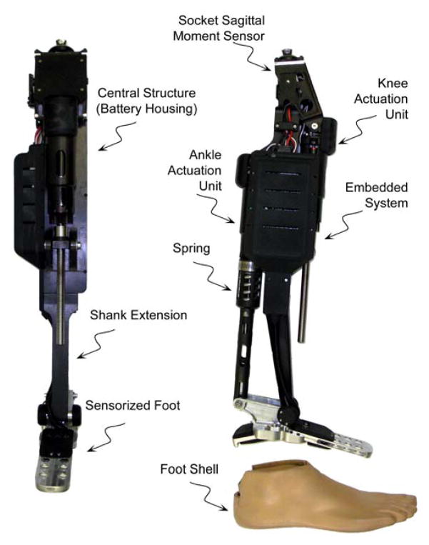
The authors have previously described a tethered powered knee and ankle prosthesis [12]. A new (previously unreported) self-contained version of the prosthesis, shown in Fig. 1, was used for the powered sit-to-stand and assistive stand-to-sit testing, described herein. The powered prosthesis is a two degree of freedom robotic device capable of generating human-scale torque and power at the knee and ankle joints. Actuation of each joint is accomplished via slider-crank linkages driven by motor ball screw assemblies. The ankle actuation unit incorporates a spring to bias the motor’s axial force output toward ankle plantarflexion, and to supplement power output during ankle push off. The device’s sensor package includes a custom load cell to measure the sagittal socket interface moment above the knee joint, a custom foot to measure the ground reaction force at the heel and ball of the foot, and commercial potentiometers and load cells to measure joint positions and torques, respectively. The self-contained version hosts an embedded system allowing for both tethered and untethered operation run by either MATLAB Simulink or a PIC32 microcontroller, respectively. The prosthesis is powered by a 118 W·h lithium polymer battery that allows for approximately 1.8 hours of level ground walking at 5.1 km/h (over 4,500 strides with the prosthesis) or 12 hours of standing, estimated in initial trials with one unilateral transfemoral amputee subject.
Fig. 1.
The self-contained powered knee and ankle transfemoral prosthesis.
B. Control Architecture
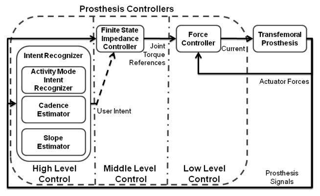
The control architecture of the prosthesis is a three level hierarchy, as diagrammed in Fig. 2. The high level supervisory controller, which is the intent recognizer, infers the user’s intent based on the interaction between the user and the prosthesis, and correspondingly switches the middle level controllers. Intent recognition is achieved by first generating a database containing sensor data from different activity modes and then training a pattern recognizer that switches between activity modes in real time, as described in [13]. A middle level controller is developed for each activity mode, such as walking, standing, sitting, and stair ascent/descent. The middle level controllers generate torque references for the joints using a finite state machine that modulates the impedance of the joints depending on the phase of the activity. The low-level controllers are the closed-loop joint torque controllers, which compensate for the transmission dynamics of the ball screw (i.e., primarily friction and inertia), and thus enable tracking of the knee and ankle joint torque references (commanded by the middle level controllers) with a higher bandwidth and accuracy than is afforded with an open-loop torque control approach. In this work, the design of the supervisory intent recognizer and the finite state impedance based controller for the sitting and standing modes will be presented.
Fig. 2.
Powered prosthesis control architecture.
C. Finite State Based Impedance Control
In the finite state impedance based control, the impedance behavior of healthy biomechanical gait is mimicked by modulating joint impedances of the prosthesis according to the phase of gait. In each phase, the knee and ankle torques, τi, are each described by a passive spring and damper with a fixed equilibrium point, given by:
| (1) |
where ki, bi, and θki denote the linear stiffness, damping coefficient, and equilibrium point, respectively, for the ith state. Switching joint impedances between the gait phases is initiated by biomechanical cues. For instance, the switching from swing extension to the early stance state during walking occurs with the detection of heel strike. The approach requires the development of a state machine for each type of user activity such as walking, standing, sitting, and stair ascent and descent. The result is an effective and predictable controller that does not violate passive behavior except when the user requests active power transfer by triggering a transition. The authors previously developed controllers for standing and walking modes using this framework [12]. Within this framework, the finite state based impedance control approach will be extended to include a state machine for sitting and the transitions between sitting and standing, Fig. 3.
Fig. 3.
The state chart depicting the phase transitions in standing and sitting modes.
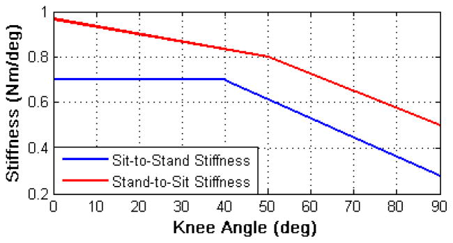
The standing impedance controller consists of two phases: weight bearing and non-weight bearing. In the weight bearing phase, the weight of the user is supported with high impedance at the joints. In the non-weight bearing mode, the knee acts as a soft dashpot to enable freedom of movement and a smooth transition to walking. While using the standing controller, the user can shift his or her weight between the sound side and the prosthesis, balance and shuffle. The sitting mode controller consists of four phases. Two are primary sitting phases, weight bearing and non-weight bearing. The other two encompass the transition phases, sit-to-stand and stand-to-sit transitions, for SU and SD, respectively. Weight bearing and non-weight bearing are the active sitting phases that switch the knee and ankle joints between high and low impedances, respectively. The transition phases, sit-to-stand and stand-to-sit, modulate the stiffness of the knee as a function of knee angle, Fig. 4, to assist the user in SU and SD. The modulation allows for smoother transitions near the seated position. The ankle joint is slightly dorsiflexed with moderate stiffness during the SU and SD phases. The parameters of the impedance based controllers are tuned using a combination of feedback from the user and joint angle, torque and power data from the prosthesis.
Fig. 4.
Knee angle modulated knee stiffness during sit-to-stand and stand-to-sit phases.
D. Intent Recognition
1) Database Generation
The prosthesis was tested on a 20-year-old male (1.93 m, 70 kg) unilateral amputee three years post amputation. The length of the test subject’s residual limb, measured from the greater trochanter to the amputated site, was 55% of the length of the non-impaired side measured from the greater trochanter to the lateral epicondyle. The subject uses an Ottobock C-leg with a Freedom Renegade prosthetic foot for daily use. The subject’s daily use socket was used on all experiments, where the powered prosthesis prototype was attached on place of the daily use prosthesis. The overall prosthesis height and varus-valgus alignment were performed by a licensed prosthetist. The prosthesis was tuned for the subject. The controller parameters for the standing and sitting mode are given in Table I and II, respectively, which were obtained by tuning as previously mentioned. The powered prosthesis was tethered to a laptop computer running MATLAB Real Time Workshop for controller implementation and data logging. The prosthesis sensor data for database generation was sampled at 1000 Hz consisted of seven signals: joint positions and velocities for the knee and ankle, socket sagittal plane moment and heel and ball of foot forces.
TABLE I.
IMPEDANCE PARAMETERS FOR STANDING FROM EXPERIMENTAL TUNING
| Knee Impedance | Ankle Impedance | |||||
|---|---|---|---|---|---|---|
| Phase | k Nm deg−1 | b N s m−1 | θk deg | k Nm deg−1 | b N s m−1 | θk deg |
| 0 | 2.5 | 0.02 | 0 | 4.0 | 0.05 | −6 |
| 1 | 0 | 0.02 | 0 | 2.0 | 0.05 | −6 |
TABLE II.
IMPEDANCE PARAMETERS FOR SITTING FROM EXPERIMENTAL TUNING
| Knee Impedance | Ankle Impedance | |||||
|---|---|---|---|---|---|---|
| Phase | k Nm deg−1 | b N s m−1 | θk deg | k Nm deg−1 | b N s m−1 | θk deg |
| 0 | 0 | 0.05 | 0 | 4 | 0.06 | 0 |
| 1 | 0 | 0.02 | 0 | 2 | 0.02 | 0 |
| 2 | 1.0 | 0 | 5 | 2 | 0.06 | 5 |
| 3 | 0.7 | 0 | 5 | 2 | 0.06 | 5 |
In order to recognize standing and sitting modes, a database was generated that contained the possible standing and sitting scenarios as outlined in Table III. The data acquired was used for designing the GMM classifiers and finding the optimal voting length for real-time controller switching. For the standing mode, two activities were considered: static and dynamic standing. The former consists of activities in which the subject stands still such as standing stationary and shifting weight between the limbs. The latter contains more active movements, such as taking small steps, turning in place, and repositioning the limb. For each of the static and dynamic standing activities, four 100-second trials were measured of which the middle 80 seconds were used for generation of the database. From the first two trials, 200 frames with random initial points for four different frame lengths, f, of 50, 100, 200, and 400 samples were extracted to generate the features for the GMM classifier. The remaining standing trials were used for voting vector length determination.
TABLE III.
DIFFERENT ACTIVITY SCENARIOS FOR DATABASE GENERATION
| Scenario | #. of trials | Activity Mode | Activity | Purpose |
|---|---|---|---|---|
| 1 | 4 | Standing | Static Standing | GMM, OVVL |
| 2 | 4 | Standing | Dynamic Standing | GMM, OVVL |
| 3 | 15 | Sitting | Standing Up | GMM |
| 4 | 15 | Sitting | Sitting Down | GMM |
| 5 | 2 | Sitting | Sitting | OVVL |
Note. GMM stands for the task of designing the GMM classifier.
OVVL stands for the task of finding the optimal voting vector length for real-time controller switching.
Generation of the database for the sitting mode was more complicated, since the finite state based impedance controller for sitting includes the SU and SD transitions. These transitions are initiated by the intent recognizer. Without a database containing these transitions, the intent recognizer cannot be designed. In order to overcome this problem, the SU and SD transitions were triggered using knee angle thresholds for generating the database. For generating the database, an activity mode change occurs during standing up in sitting mode to standing mode when the knee angle becomes less than 5 degrees. For sitting down, the finite state based impedance controller is switched to sitting mode when the knee angle exceeds 5 degrees. Fifteen trials for both cases are conducted. The four seconds after the sitting down transition and four seconds before the SU transition are recorded for generating the feature frames for the GMM classifier design. From each trial 20 frames of length 50, 100, 200 and 400 samples are generated. Moreover, two 100-second sitting trials were recorded for finding the optimal voting vector length for sitting to standing transitions. During these trials, the subject sat on a stool, did sitting activities such as repositioning limbs, changing orientation, and reaching an object excluding SU transition. For each frame length, the database for the GMM classifier design included 800 frames of standing data and 600 frames of sitting data.
2) Feature Extraction
The real-time nature of the problem requires that the features extracted from the seven prosthesis signals be computationally inexpensive, and as such, the mean and standard deviation were selected as features to extract from each frame, resulting in 14 fundamental simple time domain features. After the features were extracted, they were normalized into the range of [−1, 1] to eliminate the scaling effects between different features. Balancing the information content of a frame against frame length is important since additional delay for intent recognition is introduced as the frame size grows. In order to find the optimal frame length, different frame sizes (50, 100, 200 and 400 samples) were considered.
3) Dimension Reduction
In order to decrease the time required for real-time intent recognition and training and prevent over-fitting, the feature space was reduced (at the cost of information content) using Principal Component Analysis (PCA) [14] and Linear Discriminant Analysis (LDA) [15], from 14 dimensions to a feature space of 1, 2 and 3 dimensions. Both approaches employ linear transformations, which only necessitate a matrix multiplication operation. Since orthonormal transformations tend to decrease the magnitude of the elements in the transformed matrix as compared to the initial matrix, the reduced features are normalized into the range of [−1, 1] to avoid any possible numerical instability in the GMM classification phase.
4) Gaussian Mixture Model Activity Mode Classification
Gaussian Mixture Models (GMM) are used to characterize the probability that the user and prosthesis is engaged in a given activity mode. Specifically, a separate GMM is used to describe each activity mode, wi. For some set of inputs x⃗, the probability of being in an activity mode, wi, is given by:
| (1) |
where
| (2) |
where K is the number of components of the mixture model, is the mixture parameter of the ith GMM for the kth component, which satisfy the constraints and . The mixture component, , is a multivariate Gaussian probability density function with a D×1 mean vector, , and D×D full covariance matrix, , with D(D +1)/2 free parameters. Each GMM can be parameterized by K(1+ D + D(D +1)/2) − 1 parameters, which are the mixture parameters, mean vectors and covariance matrices, notated as . Once the GMM’s are parameterized, for a given sample feature vector, x⃗S, the activity mode, wm, is selected as the mode with the highest probability:
| (3) |
Parameterization of the GMM’s for all desired activity modes is achieved based on training data in an iterative fashion with the Expectation Maximization (EM) algorithm [16]. Several initialization schemes for EM are suggested in [17]. In this work, the reduced dataset for an activity mode, wi, is roughly clustered using the k-means algorithm [18]. These clusters are used to initialize the EM algorithm for finding the mixtures. A key factor affecting the classification performance of GMM’s is the number of mixture components, K. As such, the performance of the models for a range of mixture components should be considered and compared for a given application.
5) Model Selection
The model search space consists of 42 models, which in turn consist of 6 dimension methods (i.e., PCA and LDA for 1 to 3 dimensions) applied to 7 GMM models ranging from order 2 to 8, for each frame length. In order to find the best classifier for each frame length, the Area under the Receiver Operator Characteristics curve (AUC) [19] is used as the performance metric. The reason for choosing AUC is twofold. Firstly, it provides a comprehensive metric that computes true and false positives for all possible classification thresholds observed in the data. Secondly, the AUC metric is insensitive to class distribution. 10-fold cross-validation (CV) [20] is employed to avoid over-fitting. In 10-fold CV, the data is split into 10 sets of size N/10. For purposes of model selection, the classifier is trained on 9 datasets and tested for the AUC on the remaining one. This is repeated ten times until all the data splits are tested and the mean AUC score is recorded as the performance metric of a specific classifier.
6) Voting Scheme for Controller Mode Switching
The activity mode intent recognizer is a component of the supervisory controller for the powered prosthesis and has two performance objectives. The first objective is to switch to another mode in the shortest time possible when a mode transition occurs, and the second objective is to avoid switching to another mode when there is no real transition. With respect to the first objective, a longer switching time will decrease the quality of movements since the user will have a perceived latency of the assistance from the prosthesis. However, failure to meet the second objective could have more severe consequences (i.e. causing loss of balance and even a fall). Therefore, to increase assurance of correct mode switching, a voting scheme is used.
In the real-time implementation, overlapping frames are classified at each 10 ms interval (Δt ). In the voting scheme, the last l classifier decisions are stored in a voting vector and mode switching occurs if more than 90 percent of the classification results are in agreement. To avoid chattering during transition and increase the robustness of the powered prosthesis control, a rule was introduced to not allow the controller mode to switch for 500 ms after a mode switching occurs.
The combination of the voting length, l, and the frame length, f, determines the delay of activity mode intent recognition. To optimize the voting vector length, l, the last two trials for each scenario in the experimental database were used. In this process, the real-time activity intent recognizer is implemented offline with possible voting vector length from 10 to 100 in increments of 10. For a specific frame length, f, the smallest voting length, ls, which does not switch to standing for the sitting trials and to standing for sitting trials, is selected as the optimal voting vector length.
Once the optimal voting length for each frame is found, the best frame length for the real-time activity intent mode recognition needs to be determined. It is assumed that the two trials for each scenario encompass all the possible cases and the best models for each frame length are reliable, meaning they do not result in incorrect controller switching. Hence, the problem becomes to select the frame length which yields the least amount of delay, d, in the intent recognition. This is accomplished by computing an approximate delay score, d = f/2+10l, for each frame length.
III. Results and Discussions
A. Real-time Intent Recognition
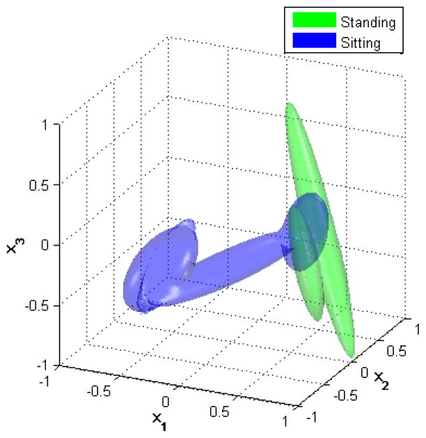
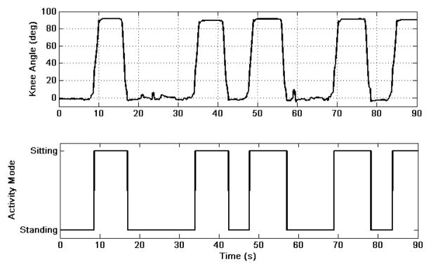
The intent recognition analysis returns the GMM with 6 mixtures using three dimensional PCA reduction using 100 sample frames as the best model. The voting vector length for this model is 40 resulting in an approximate delay of 450 ms. Surface plots of the standing and sitting GMMs showing the regions of the feature space with greater than 0.05 probability densities are presented in Fig. 5. The distinct locations of the two different activities in the reduced feature space can be seen in this figure. It should be noted that the SU and SD transitions look like a bridge connecting the standing and sitting modes in this plot. The best model (the model with the least delay) is used for real-time intent recognition between the standing and sitting activity modes. Five trials lasting 90 seconds were conducted to verify that the supervisory controller works in a closed feedback loop. During each trial, the experimenter gave audio cues to the subject to stand up and sit down. During the five trials, no erroneous mode changes were observed. The prosthetic knee angle and the activity mode for one of the trials are shown in Fig. 6. The subject stated that there was no perceived latency during transitions. This also agrees with the fact that the knee trajectories for SU and SD transitions are smooth. One might argue that instead of designing a complex intent recognizer a simple thresholding scheme such as implemented for the database generation might suffice for initiating SU and SD transitions. As can be observed from Fig. 6, however, the knee angle threshold used for generating the database (5 degrees) is exceeded many times during standing. If this threshold were used, many incorrect stand-to-sit transitions would be initiated. The intent recognizer creates an intricate switching function combining many measurements which results in a robust supervisory controller.
Fig. 5.
Gaussian Mixture Model surface plots of the standing and sitting modes showing the regions of the feature space, where the probability density function is greater than 0.05, for the three dimensional PCA reduced data.
Fig. 6.
Prosthetic knee angle (top) and the real-time activity mode switching (bottom) for a 90 seconds standing and sitting trial.
B. Biomechanical Evaluation
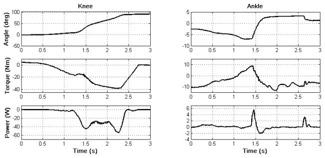
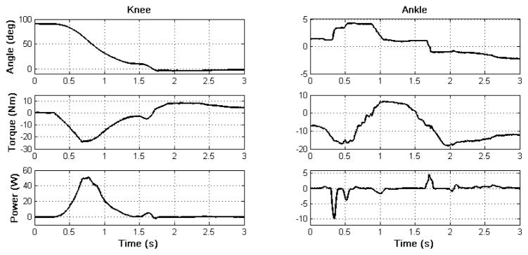
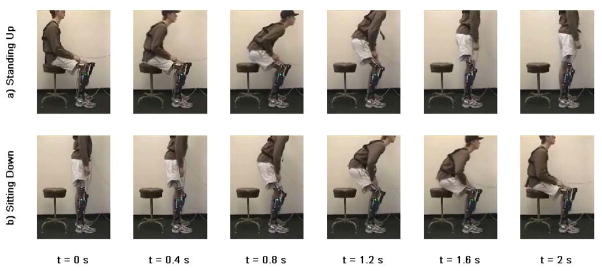
The knee and ankle angles, torques and powers are shown in Figs. 7 and 8 for SU and SD, respectively. The corresponding video frame plot showing the middle two second period of these transitions are in Fig. 9. In standing up, the prosthesis generates peak torque of around 25 Nm and positive peak power of 50 W at the knee during SU. During SD, a smooth descent with up to 50 W of power dissipated at the knee is observed. Even though no significant power and torque was registered at the ankle, the active ankle joint increases stability by adjusting the ankle angle to keep the foot flat during the SU and SD transitions. It should be noted that the powered prosthesis is capable of generating higher torques than those in Figs. 7 and 8 but the parameters were tuned such that the subject feels most comfortable. The relatively short residual limb length of the subject could limit the maximum comfortable knee torque during SU. The subject stated while using the powered prosthesis it was easier for him to stand up and he feels more support from the prosthesis relative to using his passive one. Presumably, the increased support from the powered prosthesis reduced the joint torques and powers required during standing up from the sound side, although these were not measured in the experimental trials.
Fig. 7.
Knee and ankle angles (top), torques (middle) and powers (bottom) during sitting down.
Fig. 8.
Knee and ankle angles (top), torques (middle) and powers (bottom) during standing up.
Fig. 9.
Video frames of standing up (a) and sitting down (b) transitions.
IV. Conclusion
This paper describes a novel control framework for standing and sitting down with a powered knee and ankle prosthesis. The results indicate that the high level controller (intent recognizer) infers user’s intent without perceived latency by the user and switches the underlying controllers correctly. Operating in the proposed control framework, the powered prosthesis was able contribute significant net power to the user at the knee joint during standing up that could not have been achieved with passive prostheses. Further work includes comprehensive biomechanical evaluation of the assistive sit-to-stand and stand-to-sit control framework on multiple amputee subjects.
Supplementary Material
Acknowledgments
This work was supported by the National Institutes of Health grant no. R01EB005684-01. The authors also gratefully acknowledge the support of Otto Bock Healthcare Products for donation of prosthetic components.
Contributor Information
Huseyin Atakan Varol, Email: atakan.varol@vanderbilt.edu, Department of Electrical Engineering and Computer Science, Vanderbilt University, Nashville, TN 37235 USA.
Frank Sup, Email: frank.sup@vanderbilt.edu, Department of Mechanical Engineering, Vanderbilt University, Nashville, TN 37235 USA.
Michael Goldfarb, Department of Mechanical Engineering, Vanderbilt University, Nashville, TN 37235 USA.
References
- 1.Lindemann U, Claus H, Stuber M, Augat P, Muche R, Nikolaus T, Becker C. Measuring power during the sit-to-stand transfer. European J of Applied Physiology. 2003 Jun;89(5):466–470. doi: 10.1007/s00421-003-0837-z. [DOI] [PubMed] [Google Scholar]
- 2.Galli M, Cimolin V, Crivellini M, Campanini I. Quantitative analysis of sit to stand movement: Experimental set-up definition and application to healthy and hemiplegic adults. Gait & Posture. 2008 Jul;28(1):80–85. doi: 10.1016/j.gaitpost.2007.10.003. [DOI] [PubMed] [Google Scholar]
- 3.Kralj A, Jaeger RJ, Munih M. Analysis of Standing up and Sitting down in Humans - Definitions and Normative Data Presentation. J of Biomechanics. 1990;23(11):1123–1138. doi: 10.1016/0021-9290(90)90005-n. [DOI] [PubMed] [Google Scholar]
- 4.Janssen WGM, Bussmann HBJ, Stam HJ. Determinants of the sit-to-stand movement: A review. Physical Therapy. 2002 Sep;82(9):866–879. [PubMed] [Google Scholar]
- 5.Schenkman M, Berger RA, Riley PO, Mann RW, Hodge WA. Whole-body movements during rising to standing from sitting. Physical Therapy. 1990 Oct;70(10):638–648. doi: 10.1093/ptj/70.10.638. [DOI] [PubMed] [Google Scholar]
- 6.Burger H, Kuzelicki J, Marincek C. Transition from sitting to standing after trans-femoral amputation. Prosthetics and Orthotics International. 2005 Aug;29(2):139–151. doi: 10.1080/03093640500199612. [DOI] [PubMed] [Google Scholar]
- 7.Berry D. Microprocessor prosthetic knees. Phys Med Rehabil Clin N Am. 2006 Feb;17(1):91–113. vii. doi: 10.1016/j.pmr.2005.10.006. [DOI] [PubMed] [Google Scholar]
- 8.Flowers WC, Mann RW. Electrohydraulic knee-torque controller for a prosthesis simulator. ASME J of Biomechanical Engineering. 1977;99(4):3–8. doi: 10.1115/1.3426266. [DOI] [PubMed] [Google Scholar]
- 9.Popovic D, Schwirtlich L. Belgrade active A/K prosthesis. In: de Vries J, editor. Electrophysiological Kinesiology, Intern. Congress Ser. No. 804. Excerpta Medica; Amsterdam, The Netherlands: 1988. pp. 337–343. [Google Scholar]
- 10.Bedard S, Roy P. Actuated Leg Prosthesis for Above-Knee Amputees. U. S. Patent. 2003
- 11.Martinez-Villalpando E, Weber J, Elliott G, Herr H. Design of an agonist-antagonist active knee prosthesis. Proc. IEEE/RAS-EMBS Int. Conf. on Biomedical Robotics and Biomechatronics; 2008. pp. 529–534. [Google Scholar]
- 12.Sup F, Varol HA, Mitchell J, Withrow T, Goldfarb M. Design and control of an active electrical knee and ankle prosthesis. Proc. IEEE/RAS-EMBS Int. Conf. on Biomedical Robotics and Biomechatronics; 2008. pp. 523–528. [DOI] [PMC free article] [PubMed] [Google Scholar]
- 13.Varol HA, Sup F, Goldfarb M. Real-time gait mode intent recognition of a powered knee and ankle prosthesis for standing and walking. Proc. IEEE/RAS-EMBS Int. Conf. on Biomedical Robotics and Biomechatronics; 2008. pp. 66–72. [DOI] [PMC free article] [PubMed] [Google Scholar]
- 14.Jolliffe IT. Principal Component Analysis. 2. New York: Springer; 2002. [Google Scholar]
- 15.Fisher RA. The statistical utilization of multiple measurements. Annals of Eugenics. 1938;8:376–386. [Google Scholar]
- 16.Dempster AP, Laird NM, Rubin DB. Maximum likelihood from incomplete data via EM algorithm. J of the Royal Statistical Society Series B-Methodological. 1977;39(1):1–38. [Google Scholar]
- 17.McLachlan GJ, Peel D. Finite mixture models. New York: Wiley; 2000. [Google Scholar]
- 18.Hartigan JA, Wong MA. A K-means clustering algorithm. Applied Statistics. 1979;28(1):100–108. [Google Scholar]
- 19.Fawcett T. An Introduction to ROC Analysis. Pattern Recognition Letters. 2006 Jun;27(8):861–874. [Google Scholar]
- 20.Mitchell TM. Machine Learning. New York: McGraw-Hill; 1997. [Google Scholar]
Associated Data
This section collects any data citations, data availability statements, or supplementary materials included in this article.


