Abstract
In this study, a new concept for particle size prediction during the fluid bed granulation is presented. Using the process measurements data obtained from a design of experimental study, predictive partial least squares models were developed for spraying and drying phases. Measured and calculated process parameters from an instrumented fluid bed granulation environment were used as explaining factors, whereas an in-line particle size data determined by spatial filtering technique were used as response. Modeling was carried out by testing all possible combinations of two to six process parameters (factors) of the total of 41 parameters. Eleven batches were used for model development and four batches for model testing. The selected models predicted particle size (d50) well, especially during the spraying phase (Q2 = 0.86). While the measured in-line d50 data were markedly influenced by different process failures, e.g., impaired fluidization activity, the predicted data remained more consistent. This introduced concept can be applied in fluid bed granulation processes if the granulation environment is soundly instrumented and if reliable real-time particle size data from the design of experiment batches are retrieved for the model development.
Key words: fluid bed granulation, granule growth, modeling, particle size distribution, process analytical technology (PAT)
INTRODUCTION
Fluid bed granulation (FBG) is one of the most widely used and extensively studied processes in pharmaceutical technology. The prime purpose of the FBG is to improve material properties for further processing, i.e., flowability and compactibility. Particle size distribution has a major impact on these properties. FBG involves three simultaneous processes: (1) wetting and nucleation, (2) consolidation and growth, and (3) breakage and attrition. Since it is difficult to distinguish these rate processes from each other, some more practical partitioning of the process is required. Thermodynamically, it is reasonable to split FBG process and the modeling in two separate stages: (1) binder spraying phase and (2) drying phase, since material input into the processing chamber is fundamentally different in these two stages.
During the FBG process, granule growth rate and size are influenced by the establishment of a critical dynamic equilibrium between granule wetting and evaporation from the granule surface (1). The process parameters affecting granule wetting are granulation fluid volume and addition rate, atomizing air spray pressure and position, and design of the spray nozzle. Evaporation from the granule surface is governed by the drying capacity of the inlet air, a factor in turn governed by inlet air temperature, flow rate, humidity, and distribution. It is commonly understood that careful and accurate control and monitoring of this complex set of interrelated parameters is important (2–23).
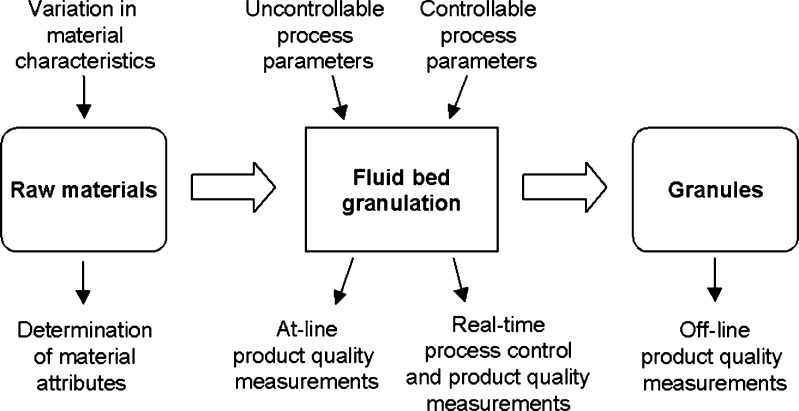
Understanding and controlling of FBG process also requires sophisticated instrumentation. Air flow rates, air humidity, pressure differences, temperature values, and granulation liquid feed rate values are typical process measurements that are determined during the FBG. A schematic overview illustrating the variation and measurement aspects in FBG is shown in Fig. 1. Even though most sources of variation can be kept in control, some process parameters may remain uncontrollable. If there is, e.g., no effective air-dehumidifying system in place, inlet air humidity can vary remarkably during the year, and it is, therefore, an important uncontrollable variable. The impact of air humidity effect is, however, dependent on the formulation used. Another example is batch to batch variation in raw material characteristics. If an uncontrollable variation influences the product quality attributes, the process should be adjusted to compensate for this. In practice, process adjustment is possible if process understanding can be scientifically demonstrated (24,25).
Fig. 1.
Overview of fluid bed granulation process
Traditionally, and quite commonly still today, the determination of the product quality is carried out by off-line measurement after the process. Various techniques, such as sieve analysis (26), laser diffraction (27,28), and image analysis (29–31), are available for off-line particle size distribution measurement. Recently, also spatial filtering technique (SFT) has been utilized for particle size determination (32). In SFT, the measured particles are dispersed using pressurized air through the measurement zone inside the probe. The velocity and the chord length size of the particles are measured as they move through the laser beam and hence, prohibit light entrance to the detectors. One disadvantage of these off-line applications is, however, that no data is obtained from the granule growth/attrition during the process, and therefore, real-time process adjustment is not possible. Due to this, more and more effort has been put into techniques that can be applied as in-line, online, or at-line (33–40).
When all relevant process parameters are measured, and a real-time particle size is determined during the FBG, correlations between these can be studied. Consequently, better understanding of the particle size growth and attrition can also be attained. The aim of this study was to introduce a new concept for real-time particle size prediction in FBG. The previous study reports focused on process understanding and determination of particle size during the FBG (32,40). The process measurement and in-line particle size data gathered in those studies were used here to evaluate the possibility of the real-time particle size prediction using the measured process data.
MATERIALS AND METHODS
Materials
Each batch consisting of 2.0 kg theophylline anhydrate (200 M, BASF Aktiengesellschaft, Ludwigshafen, Germany) and 2.0 kg α-lactose monohydrate (200 M, DMV International GmbH, Veghel, Netherlands) was granulated, using 2 kg of 7.5% aqueous binder solution of polyvinylpyrrolidone (Kollidon K-30; BASF).
Granulation Batches
The granulations were performed in an automated fluid bed granulator (Glatt WSG 5; Glatt GmbH, Binzen, Germany). The inlet air humidity of the process air was modified using a humidifier (Defensor Mk4; Brautek Oy, Espoo, Finland). The atomization pressure was 0.1 MPa, and the nozzle height was set to 45 cm from the distributor plate. The inlet air temperature was 40ºC during the mixing and spraying phases and was raised to 60ºC during the drying phase. The inlet airflow rates were adjusted to 0.04 m3/s for the mixing and 0.08 m3/s for the granulation/drying phases. A mixing time of 2 min was used. The final moisture content of the granules, measured by loss-on-drying (Sartorius Thermocontrol MA 100; Sartorius, Göttingen, Germany), was not more than 1.1% in all batches.
A central composite face-centered experimental design with three midpoint repetitions was used. Inlet air humidity, granulation liquid feed rate, and granulation liquid feed pulsing were studied at three levels. The parameter values were selected to generate sufficient range of different particle size growth and final particle size levels among the batches. The inlet air humidity levels were >13 (high), 7–12 (medium), and <6 g/m3 (low). The granulation liquid feed rate values were 90, 70, and 50 g/min. Granulation liquid feed pulsing was initiated after half of the total liquid amount (2,000 g) was sprayed. The granulation liquid feed was interrupted for 1 min every second minute (50% pause time), every third minute (33% pause time), or not at all (0% pause time). The granulations were performed in randomized order. The experimental study set included 17 batches; however, in-line particle size data could be collected from 15 batches that are listed in Table I.
Table I.
Design of Experiment and Actual Process Parameter Values
| Batch | Average water content of inlet air | Granulation liquid feed rate | Pause time in liquid feeding | |||
|---|---|---|---|---|---|---|
| Level | g/min | Level | g/min | Level | % | |
| 1a | −1 | 5.3 | −1 | 50 | −1 | 0 |
| 2 | 1 | 15.9 | −1 | 50 | −1 | 0 |
| 3 | −1 | 4.8 | 1 | 90 | −1 | 0 |
| 4 | −1 | 4.2 | −1 | 50 | 1 | 50 |
| 5 | 1 | 18.3 | −1 | 50 | 1 | 50 |
| 6a | −1 | 5.0 | 1 | 90 | 1 | 50 |
| 7 | 1 | 16.2 | 1 | 90 | 1 | 50 |
| 8 | −1 | 4.7 | 0 | 70 | 0 | 33 |
| 9 | 1 | 15.2 | 0 | 70 | 0 | 33 |
| 10 | 0 | 10.2 | −1 | 50 | 0 | 33 |
| 11 | 0 | 9.4 | 1 | 90 | 0 | 33 |
| 12 | 0 | 8.9 | 0 | 70 | −1 | 0 |
| 13a | 0 | 9.0 | 0 | 70 | 1 | 50 |
| 14 | 0 | 9.1 | 0 | 70 | 0 | 33 |
| 15a | 0 | 8.6 | 0 | 70 | 0 | 33 |
aBatches used for model testing
In-line Particle Size Measurements
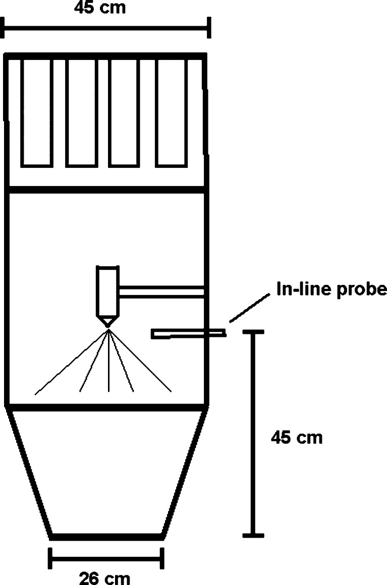
An in-line SFT probe (Parsum® IPP 70; Gesellschaft für Partikel-, Strömungs-, und Umweltmesstechnik GmbH, Chemnitz, Germany) was installed to the granulator at the height of 45 cm (Fig. 2). The particles passed through an aperture (diameter 4 mm), and pressurized air was used to disperse the particles. Measured raw data were collected via analog/digital converter to the PC (Pentium II, 2 GHz, 40 GB HDD, 512 MB RAM). The SFT software operated in the Windows® XP environment. During the fluid bed process, an average volume particle size at 10-s intervals was saved. Fifty percent fractile value (d50) of the volume particle size distribution was used for data analysis.
Fig. 2.
Fluid bed granulator
Data Pretreatment and Modeling
Partial Least Squares (PLS) was used for the data modeling. PLS is a projection method relating two data matrices to each other by a multivariate model. The PLS method enables modelling of data in which the number of variables exceeds the number of observations. It can be used, e.g., for multivariate calibration and for process modeling and optimization. More detailed information on PLS can be found in literature (41,42).
Twenty-two measured and 19 derived process parameters were used as factors, and the in-line d50 values were used as a response in PLS modeling. For spraying phase model, the actual d50 values were used. The change in d50 values from the start of drying phase was used for drying phase model. The complete list of all 41 process parameters is presented in Table II. It was realized that the derived and measured parameters do have correlations. The derived parameters, however, were included in order to get better insight of the granulation phenomena. Water balance is one example of a derived parameter that compiles many relevant FBG parameters, and hence, it enables more comprehensive evaluation of granulation.
Table II.
Measured and Derived Parameters in Glatt WSG 5 Fluid Bed Granulator
| Parameter | Abbreviation | Unit | Example numerical values from batch 3 | |
|---|---|---|---|---|
| Mean | Min–max | |||
| Measured | ||||
| Temperature of process room | T1 | ºC | 20 | 20–21 |
| Temperature after heater | T2 | ºC | 53 | 39–81 |
| Temperature of air before granulator | T3 | ºC | 46 | 38–62 |
| Temperature of air before granulator | T4 | ºC | 47 | 40–63 |
| Temperature of mass | T5 | ºC | 24 | 18–46 |
| Temperature of granulation chamber | T6 | ºC | 23 | 18–45 |
| Temperature of granulation liquida | T7 | ºC | 22 | 22–22 |
| Temperature after filters | T8 | ºC | 24 | 19–40 |
| Temperature after filters | T9 | ºC | 25 | 21–38 |
| Temperature on the chamber wall | T10 | ºC | 24 | 21–36 |
| Temperature in the outlet air duct | T11 | ºC | 27 | 24–36 |
| Pressure difference over filters | dP1 | kPa | 109 | 0–208 |
| Pressure difference over granules | dP2 | kPa | 213 | 0–314 |
| Relative humidity of inlet air | U1 | RH% | 27 | 15–29 |
| Relative humidity of outlet air | U2 | RH% | 57 | 12–82 |
| Flow rate of inlet air | F in | g/s | 72 | 12–102 |
| Flow rate of outlet air | F out | g/s | 82 | 18–124 |
| Fan speed, value of frequency converter | Fan speed | 1/s | 4,079 | 2,290–4,593 |
| Control current of heating element | Current | mA | 363 | 67–700 |
| Pump rotation speed of granulating liquida | N1 | rpm | 18 | 2–21 |
| Amount of granulation liquid sprayed (scale)a | M1 | g | 995 | 0–1,993 |
| Granulation time | Time | s | 1,280 | 130–2,430 |
| Derived | ||||
| Absolute humidity of inlet air | AH1 | g/m3 | 5 | 4–5 |
| Absolute humidity of outlet air | AH2 | g/m3 | 12 | 4–16 |
| Flow rate of inlet air | F1 | l/s | 17 | 1–30 |
| Flow rate of outlet air | F2 | l/s | 22 | 2–44 |
| Fluidization parameter, F in/Fan speed | Flow ind | g/rev | 0.018 | 0.003–0.024 |
| Specific enthalpy of water vapor in inlet air | Lat heat | kJ/kg | 165 | 29–473 |
| Cumulative enthalpy of water vapor in inlet air | Lat heat cum | kJ/kg | 14,700 | 412–38,400 |
| Average flow of granulating liquid from starta | AveM | g | 63 | 0–75 |
| Flow rate of granulation liquid in a seconda | dM | g/s | 13 | 0–20 |
| Cumulative water amount of inlet air | Water in cum | g | 418 | 9–824 |
| Cumulative water amount of outlet air | Water out cum | g | 1,268 | 7–2,391 |
| Water in cum + M1—water out cum | Water balance | g | 502 | 1–877 |
| Pressure difference over filters—pressure difference over filters with empty granulator with equal flow rate | dP1eff | kPa | 98 | 1–196 |
| Pressure difference over granules—pressure difference over granules with empty granulator with equal flow rate | dP2eff | kPa | 124 | 2–197 |
| U1–U2 | dU | RH% | −30 | −54–(+12) |
| AH1–AH2 | dAH | g/m3 | −8 | −11–0 |
| Specific enthalpy of water vapor in outlet air | Lat heat out | kJ/kg | 208 | 35–335 |
| Cumulative enthalpy of water vapor in outlet air | Lat heat out cum | kJ/kg | 22,421 | 462–48,563 |
| Cumulative enthalpy of water vapor in inlet air—cumulative enthalpy of water vapor in outlet air | Energy balance | kJ/kg | 7,680 | 50–12,643 |
Min minimum, max maximum
aParameters not used in drying phase
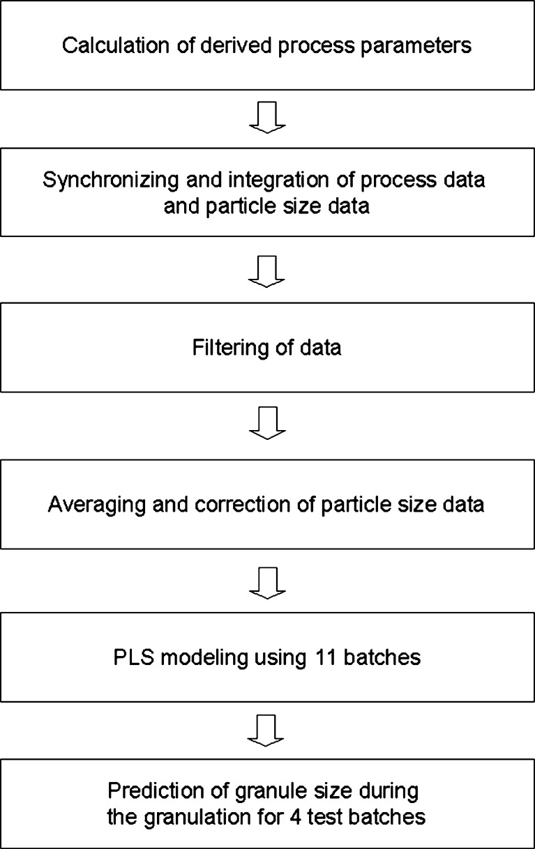
The general process for data pretreatment and modeling is presented in Fig. 3. At first the process, data were synchronized and integrated with the d50 data. The process measurement data were saved at every 1 s whereas the d50 data were received only at every 10 s, and therefore, the process measurement data was filtered to have the same amount of time points. Because one measurement represents quite a small sample from the total mass, it can still have some random noise, and therefore, a moving average of six consecutive measurements was used. It was found in previous studies that the in-line application systematically underestimates the particle size (40). Due to this, the d50 data were finally corrected using the Eq. 1, where X represents the original d50 values (micrometer), and Y represents the corrected values (micrometer).
 |
1 |
Fig. 3.
Schema for data pretreatment
Eleven batches from the experimental study set were selected for PLS model development and four batches for model testing. The test batches are marked with asterisk in Table I. As reported earlier, there were different process phenomena among the manufactured batches that caused inconsistencies in the in-line particle size data acquisition during the granulation process (40). Selection criterion here was such that all batches used in the model development had consistent and successful in-line d50 data, whereas in three out of the four test batches had different process failures and hence, some inconsistencies in the d50 data. Consequently, it was also possible to evaluate the robustness of the model by comparing the predicted and measured d50 data during the process failures.
Different models were developed for spraying phase and drying phase. Matlab software (version 7.0 in Windows XP) was programmed to model all possible two to six process parameter permutations. The constructed PLS models were based on linear combinations of these parameters. Computer’s (1.6 GHz, 500 Mb) calculation time using six parameters was approximately 20 h resulting 22.5 million models using 4.5 million combinations and all possible one to five principle components. Root mean square error of prediction (RMSEP) and statistical significance evaluation of the parameters were used to compare and rank the models. Consequently, the selected models had the smallest RMSEP value assuming that all parameters were statistically significant.
RESULTS
Prediction Models
The best models with using two to six parameters are shown in Table III. The RMSEP values of the spraying phase model decreased when the number of the parameters increased, as expected. However, it was also found that if more than four parameters were used in the spraying phase model, the coefficient values were not statistically significant anymore. Therefore, to decrease the risk of over modeling and to enable the stability of the model, four parameters were used in the spraying phase model. Using this model, the RMSEP was 30.0 µm.
Table III.
Best Models Using Two to Six Parameters
| Spraying phase models | |||||
| Water balance | Fan speed | ||||
| Water balance | Water out cum | T4 | |||
| Water balance | Water out cum | F1 | dP2 | ||
| Water balance | Water out cum | F1 | dP2 eff | T5 | |
| Water balance | Water in cum | AH1 | dU | dP2 eff | dP2 |
| Drying phase models | |||||
| Water balance | dP1 eff | ||||
| Water balance | dP1 eff | dP2 | |||
| Water balance | dU | Time | dP1 eff | ||
| Water balance | dU | Time | dP1 eff | dP2 | |
| Water balance | AH1 | AH2 | dU | T4 | T6 |
The selected spraying phase model included following parameters: water balance, water out cum, F1, and dP2. The goodness of prediction (Q2) value for the model was 0.86. Water balance and water out cum had the biggest impact on the model which can be seen as high variable influence on projection (VIP) and coefficient values (Table IV). Water balance was actually present in all of the models regardless of the amount of the parameters used and can, therefore, be regarded as the most significant single parameter for the d50. When the coefficient values of the model are evaluated, it is seen that the increase in water balance increases the d50 value, and the increase in water out cum decreases it. This is logical since the first parameter describes the amount of the water accumulating in the granulator whereas the second parameter reflects the cumulative water amount released from the process. The influence of the other two parameters, F1 and dP2, on the model was very likely related to the decreased air flow through the smallest particles. Consequently, the bigger the particles, the higher the inlet air flow rate and hence, the smaller the pressure difference over the granules.
Table IV.
VIP and Coefficient Values of the Selected Models
| Spraying phase model | ||
| VIP | Coefficient | |
| Water balance | 1.40 | 1.24 |
| Water out cum | 1.00 | −0.546 |
| F1 | 0.730 | 0.178 |
| dP2 | 0.698 | −0.117 |
| Drying phase model | ||
| VIP | Coefficient | |
| dU | 1.24 | 1.66 |
| Water balance | 1.14 | 0.585 |
| AH1 | 1.05 | −1.03 |
| T6 | 1.01 | −1.10 |
| AH2 | 0.805 | 0.564 |
| T4 | 0.636 | 0.499 |
VIP variable influence on projection
It was not sensible to calculate the RMSEP values for drying phase due to the inconsistencies in d50 data of the three test batches. However, it was found that using the model of six parameters, all parameter coefficients had statistical significance on the model. Therefore, six parameters were used for drying phase model. The drying phase model included following parameters: dU, water balance, AH1, T6, AH2, and T4.
Prediction Results
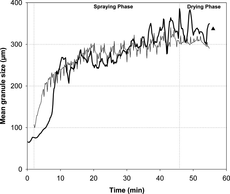
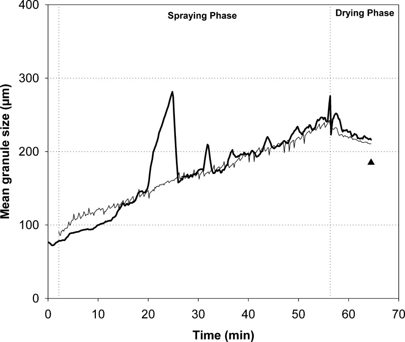
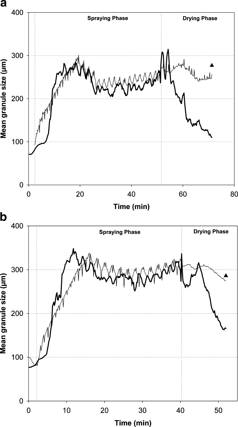
The predicted and measured d50 values of the four test batches are presented in Figs. 4, 5, and 6. In general, the predicted d50 values were in good correspondence with the observed values. For batch 15, which was a midpoint batch of the experimental design, the predicted values followed particularly well the measured data (Fig. 4). There were inconsistencies in the original in-line particle size data acquisition with the batches 1, 6, and 13. During the spraying phase of batch 1 (approximately at 21 min time point), the measured d50 values rapidly increased due to the diminishing of the filter shaking. This abnormality, however, was not reflected to the predicted data. It was found that the predicted trend of the particle size increase was very stable also during this process failure (Fig. 5). Furthermore, there was a turning point in the original d50 trend at the time when the drying phase started. The model predicted this trend very similarly to the obtained data. The measured d50 values were decreased at the end of the drying process of two batches due to the blocking of the distributor plate and decreased fluidization activity (Fig. 6). The prediction results, on the contrary, revealed clearly more consistent d50 trend until the end of the process. When the final d50 values measured off-line by SFT are compared to the predicted level, it is found that the selected model predicts reasonably well the final particle size. Especially, with batches 6 and 13 that had impaired fluidization, the predicted d50 values were more accurate than those of the observed in-line data during the end of the process.
Fig. 4.
Observed (thick line) and predicted (thin line) d 50 values for batch 15. Triangle represents the d 50 value of the final granules measured off-line
Fig. 5.
Observed (thick line) and predicted (thin line) d 50 values for batch 1. Triangle represents the d 50 value of the final granules measured off-line
Fig. 6.
Observed (thick line) and predicted (thin line) d 50 values for batches 6 (a) and 13 (b). Triangle represents the d 50 value of the final granules measured off-line
DISCUSSION
Biggest systematic differences between the modeled and the observed d50 values were obtained at the beginning of the granulation, where the increase in the observed d50 values was very fast. The number of process measurement time points representing the fast granule growth (nucleation) phase was very limited and small compared to the slow growth phase. Consequently, the model describes the slow growth phase better. If the nucleation phase was in focus, a separate model could have been constructed to better predict the fast granule growth. This would have been justified, since the factors and the magnitude of the factors that influence the granule growth in the nucleation phase are probably different compared to those in the slow granule growth phase. However, in this study, the detailed modeling of the initial granule growth phase was not regarded important, because the granules in nucleation phase are still loosely bound and undergo breakage, attrition, and reagglomeration.
One variable, i.e., pulsing of the granulation liquid feed, had a major effect on the process environment. During the pause phase, the granules dried to some extent, and this causes a fluctuation phenomenon in the mass temperature with these batches (32). It is obvious that this variation observed can disturb the modeling to some extent. In future, it would be important to utilize the same kind of modeling concept to another study experiment, having a different kind of formulation and process variables to verify the concept. One useful and objective evaluation criterion for the prediction capability is the comparison of the final predicted and measured particle size.
Applicability of the Modeling Concept
In general, the prediction results by the model were very promising. Although the composition and the design of experiment were not optimal for modeling, the d50 predictability was still good. This suggests that the model parameters well covered the most relevant phenomena during the spraying phase. The possibilities of the modeling concept described here are wide; however, some restrictions exist. The main prerequisites for the development of this kind of prediction model are: (1) appropriately instrumented fluid bed granulator and (2) reliable particle size determination method during the model development. The instrumentation of a granulator is, in principle, straightforward, and commercial solutions are available. The second item is more challenging, because quite often, there are difficulties in obtaining reliable real-time particle size data during FBG. For example, it is well known that the probes applied into the process are prone to foul due to the adhesive and moist powder. In addition, the location of the probe in the chamber can affect the particle size results. Therefore, an at-line focused beam reflectance method has also been utilized (38). SFT is another good alternative to be used for fast at-line particle size analysis. It must be noticed, however, that representative sampling is of uppermost importance when applying any particle size determination method during FBG.
Design of experimental studies can be utilized to cover the desired variable ranges for the model. If, e.g., the inlet air humidity cannot be controlled in production scale environment, the effects of this uncontrollable variable could be included in smaller scale study as shown in this report. Predictive model for particle size growth can be developed in small scale, and the design space limits for the growth can be specified. In larger scale, the model can be verified and updated. In the end, the particle size trend could be predicted in real time without any in-line particle size technique or sampling procedures as long as the process variation obtained is included in the established model (i.e., design space). By doing this, the risk of in-line probe fouling and the biased particle size results due to size segregation can be avoided, too. It must be remembered, that the developed model is valid only inside the studied variable ranges, and it allows no extrapolation. The update and adjustment of the model can be, however, carried out by using the accumulative data from the manufactured batches. Although this modeling concept described is process- and equipment-dependent, we think it may have value, e.g., to support the in-house assurance of the process performance or to decrease the need of in-line particle size equipment investments in well-controlled manufacturing processes.
CONCLUSIONS
The developed models enabled the prediction of the particle size during the fluid bed granulation based on the traditional process data measurements. The goodness of prediction (Q2) and the RMSEP values for the spraying phase model were 0.86 and 30.0 µm, respectively. While the measured in-line particle size data were influenced by different process failures, e.g., decreased fluidization activity, the predicted data remained more consistent. The introduced modeling concept can be applied in fluid bed granulation if the granulation environment is soundly instrumented and if reliable real-time particle size data from the design of experiment batches are retrieved for the model development and testing.
Acknowledgments
This work was financially supported by the Finnish Funding Agency for Technology and Innovation TEKES. Anni Liimatainen, Tanja Lipsanen, and Henri Salokangas from Orion Pharma and Heikki Räikkönen and Kristian Alho from the University of Helsinki are acknowledged for their contribution to this project.
References
- 1.Frake P, Greenhalgh D, Grierson SM, Hempenstall JM, Rudd DR. Process control and end-point determination of a fluid bed granulation by application of near infrared spectroscopy. Int J Pharm. 1997;151:75–80. doi: 10.1016/S0378-5173(97)04894-1. [DOI] [Google Scholar]
- 2.Schaefer T, Wortz O. Control of fluidized bed granulation: effects of spray angle, nozzle height and starting material on granule size and size distribution. Arch Pharm Chem Sci Ed. 1977;5:51–60. [Google Scholar]
- 3.Schaefer T, Wortz O. Control of fluidized bed granulation: estimation of droplet size of atomized binder solutions. Arch Pharm Chem Sci Ed. 1977;5:178–93. [Google Scholar]
- 4.Schaefer T, Wortz O. Control of fluidized bed granulation: effects of inlet air temperature and liquid flow rate on granule size and size distribution. Arch Pharm Chem Sci Ed. 1978;6:1–13. [Google Scholar]
- 5.Schaefer T, Wortz O. Control of fluidized bed granulation: effects of binder solution and atomization on granule size and size distribution. Arch Pharm Chem Sci Ed. 1978;6:14–25. [Google Scholar]
- 6.Davies WL, Gloor WT. Batch production of pharmaceutical granulations in a fluidized bed: effects of process variables on physical properties of final granulation. J Pharm Sci. 1971;60:1869–74. doi: 10.1002/jps.2600601224. [DOI] [PubMed] [Google Scholar]
- 7.Davies WL, Gloor WT. Batch production of pharmaceutical granulations in a fluidized bed: effects of various binders and their concentrations on granulations and compressed tablets. J Pharm Sci. 1972;61:618–22. doi: 10.1002/jps.2600610428. [DOI] [PubMed] [Google Scholar]
- 8.Davies WL, Gloor WT. Batch production of pharmaceutical granulations in a fluidized bed: binder dilution effects on granulation. J Pharm Sci. 1973;62:170–1. doi: 10.1002/jps.2600620144. [DOI] [PubMed] [Google Scholar]
- 9.Rambali B, Baert L, Massart DL. Using experimental design to optimize the process parameters in fluidized bed granulation on a semi-full scale. Int J Pharm. 2001;220:149–60. doi: 10.1016/S0378-5173(01)00658-5. [DOI] [PubMed] [Google Scholar]
- 10.Gorodnichev VI, El-Banna HM, Andreev BV. The construction of uses of factorial designs in the preparation of solid dosage forms, part 2: granulation in a fluidized bed. Pharmazie. 1981;36:270–3. [PubMed] [Google Scholar]
- 11.Wan LSC, Lim KS. Action of binders in the fluidized bed granulation of lactose. STP Pharma. 1991;1:248–55. [Google Scholar]
- 12.Wan LSC, Heng PWS, Muhuri G. Analysis of growth of granules in a fluidised bed granulator. STP Pharma. 1992;2:381–6. [Google Scholar]
- 13.Niskanen T, Yliruusi J. Attrition of theophylline granules during drying in a fluidized bed granulator. Pharm Ind. 1994;56:282–5. [Google Scholar]
- 14.Lipps M, Sakr AM. Characterization of wet granulation process parameters using response surface methodology. Top-spray fluidized bed. J Pharm Sci. 1994;83:937–47. doi: 10.1002/jps.2600830705. [DOI] [PubMed] [Google Scholar]
- 15.Merkku P, Lindqvist A-S, Leiviska K, Yliruusi J. Influence of granulation and compression process variables on flow rate of granules and on tablet properties, with special reference to weight variation. Int J Pharm. 1994;102:117–25. doi: 10.1016/0378-5173(94)90046-9. [DOI] [Google Scholar]
- 16.Gordon MS. Process considerations in reducing tablet friability and their effect on in vitro dissolution. Drug Dev Ind Pharm. 1994;20:11–29. doi: 10.3109/03639049409047211. [DOI] [Google Scholar]
- 17.Liu CH, Chen SC, Lee YC, Sokoloski TD, Sheu MT. Directly compressible acetaminophen compositions prepared by fluidized-bed granulation. Drug Dev Ind Pharm. 1994;20:1911–22. doi: 10.3109/03639049409050218. [DOI] [Google Scholar]
- 18.Miyamoto Y, Ogawa S, Miyajima M, Sato H, Takayama K, Nagai T. An evaluation of process variables in wet granulation. Drug Dev Ind Pharm. 1995;21:2213–25. doi: 10.3109/03639049509065902. [DOI] [Google Scholar]
- 19.Vojnovic D, Moneghini M, Rubessa F. Experimental design for a granulation process with ‘a priori’ criterias. Drug Dev Ind Pharm. 1995;21:823–31. doi: 10.3109/03639049509026646. [DOI] [Google Scholar]
- 20.Juslin L, Yliruusi J. The effect of raw material and atomizing air pressure on the properties of granules prepared in a fluidized bed granulator. STP Pharma. 1996;6:328–34. [Google Scholar]
- 21.Watano S, Takashima H, Yoshinobu S, Miyanami K, Yasutomo T. IR absorption characteristics of an IR moisture sensor and mechanism of water transfer in fluidized bed granulation. Adv Powder Technol. 1996;7:279–89. [Google Scholar]
- 22.Watano S, Morikawa T, Miyanami K. Mathematical model in the kinetics of agitation fluidized bed granulation. Effects of moisture content, damping speed and operation time on granule growth rate. Chem Pharm Bull. 1996;44:409–15. [Google Scholar]
- 23.Watano S. Direct control of wet granulation processes by image processing system. Powder Technol. 2001;117:163–72. doi: 10.1016/S0032-5910(01)00322-9. [DOI] [Google Scholar]
- 24.International Conference on Harmonisation. ICH harmonised tripartite guideline; pharmaceutical development Q8; 2005.
- 25.Food and Drug Administration (FDA). Guidance for industry; PAT—a framework for innovative pharmaceutical development, manufacturing and quality assurance; 2004.
- 26.Washington C. Particle size analysis. Chichester: Ellis Horwood; 1992. [Google Scholar]
- 27.Etzler FM, Sanderson MS. Particle size analysis: a comparative study of various methods. Part Part Syst Charact. 1995;12:217–24. doi: 10.1002/ppsc.19950120503. [DOI] [Google Scholar]
- 28.Etzler FM. Particle size analysis: a comparison of methods. Am Pharm. 2004;7:104–8. [Google Scholar]
- 29.Laitinen N, Antikainen O, Yliruusi J. Characterization of particle sizes in bulk pharmaceutical solids using digital image information. AAPS PharmSciTech. 2003;4:383–91. doi: 10.1208/pt040449. [DOI] [PMC free article] [PubMed] [Google Scholar]
- 30.Laitinen N, Antikainen O, Rantanen J, Yliruusi J. New perspectives for visual characterization of pharmaceutical solids. J Pharm Sci. 2004;93:165–76. doi: 10.1002/jps.10529. [DOI] [PubMed] [Google Scholar]
- 31.Köhler U, List J, Witt W. Comparison of laser diffraction and image analysis under identical dispersing conditions. Nuremberg: International Congress on Particle Technology; 2007. [Google Scholar]
- 32.Närvänen T, Lipsanen T, Antikainen O, Räikkönen H, Yliruusi J. Controlling granule size by granulation liquid feed pulsing. Int J Pharm. 2008;357:132–8. doi: 10.1016/j.ijpharm.2008.01.060. [DOI] [PubMed] [Google Scholar]
- 33.Watano S, Morikawa T, Miyanami K. Kinetics of granule growth in fluidized bed granulation with moisture control. Chem Pharm Bull. 1995;43:1764–71. [Google Scholar]
- 34.Goebel SG, Steffens KJ. Online-measurement of moisture and particle size in the fluidized-bed processing with the near-infrared-spectroscopy. Pharm Ind. 1998;60:889–95. [Google Scholar]
- 35.Rantanen J, Räsänen E, Tenhunen J, Känsäkoski M, Mannermaa J-P, Yliruusi J. In-line moisture measurement during granulation with a four-wavelength near infrared sensor: an evaluation of particle size and binder effects. Eur J Pharm Biopharm. 2000;50:271–76. doi: 10.1016/S0939-6411(00)00096-5. [DOI] [PubMed] [Google Scholar]
- 36.Otsuka M, Mouri Y, Matsuda Y. Chemometric evaluation of pharmaceutical properties of antipyrine granules by near-infrared spectroscopy. AAPS PharmSciTech. 2003;4:375–81. doi: 10.1208/pt040347. [DOI] [PMC free article] [PubMed] [Google Scholar]
- 37.Findlay WP, Peck GR, Morris KR. Determination of fluidized bed granulation end point using near-infrared spectroscopy and phenomenological analysis. J Pharm Sci. 2005;94:604–12. doi: 10.1002/jps.20276. [DOI] [PubMed] [Google Scholar]
- 38.Hu X, Cunningham JC, Winstead D. Study growth kinetics in fluidized bed granulation with at-line FBRM. Int J Pharm. 2008;347:54–61. doi: 10.1016/j.ijpharm.2007.06.043. [DOI] [PubMed] [Google Scholar]
- 39.Närvänen T, Seppälä K, Antikainen O, Yliruusi J. A new rapid on-line imaging method to determine particle-size distribution of granules. AAPS PharmSciTech. 2008;9:282–7. doi: 10.1208/s12249-008-9043-y. [DOI] [PMC free article] [PubMed] [Google Scholar]
- 40.Närvänen T, Lipsanen T, Antikainen O, Räikkönen H, Heinämäki J, Yliruusi J. Gaining fluid bed process understanding by in-line particle size analysis. J Pharm Sci. doi 10.1002/jps.21486. [DOI] [PubMed]
- 41.Haaland DM, Thomas EV. Partial least-squares methods for spectral analyses. 1. Relation to other quantitative calibration methods and the extraction of qualitative information. Anal Chem. 1988;60:1193–202. doi: 10.1021/ac00162a020. [DOI] [Google Scholar]
- 42.Wold S, Sjöström M, Eriksson L. PLS-regression: a basic tool of chemometrics. Chemom Intell Lab Syst. 2001;58:109–30. doi: 10.1016/S0169-7439(01)00155-1. [DOI] [Google Scholar]


