Abstract
Gamma Knife™ stereotactic radiosurgery is capable of providing small, high gradient dose distributions to a target with a high level of precision, which makes it an excellent choice for studies of focal irradiations with small animals. However, the Gamma Knife stereotactic radiosurgery process makes use of a human-sized fiducial marker system that requires a field of view of at least 200 mm2 to relate computed tomography and magnetic resonance images to the Gamma Knife treatment planning software. Thus the Gamma Knife fiducial marker system is five to six times larger than a typical small animal subject. The required large field of view limits the spatial resolution and structural detail available in the animal treatment planning image set. In response to this challenge we have developed a custom-designed stereotactic jig and miniature fiducial marking system that allow small bore high-resolution micro-imaging techniques, such as 7T MR and micro-CT, to be used for treatment planning of Gamma Knife stereotactic radiosurgery focal irradiation of small animals.
INTRODUCTION
Translational research has gained widespread popularity in radiation oncology in recent years, with the goal of moving basic research from the bench into the clinic as quickly as possible. In many cases, a key step in this process is the development of a preclinical small animal model to validate basic scientific research. The current trend in clinical radiation oncology is to use highly conformal radiation therapy treatments (1) that deliver a large dose to the tumor while sparing surrounding normal tissues. Subsequently, we are seeing increasing interest in the use of conformal, targeted radiation in preclinical small animal work to study the mechanisms of radiation response in normal and diseased tissues for these dose distributions delivered with focal stereotactic, hypofractionated and non-homogeneous radiation beams.
Several devices based on kilovoltage X-ray technology have been developed to deliver conformal, targeted radiation fields to small animals. These units typically use both imaging and treatment capabilities in a hybrid device, similar to some clinical designs of image-guided linear accelerators (2–6). Although dedicated small animal irradiators such as these offer good resolution and performance, they may not be a possibility for every research group due to the expense and expertise required for their construction. Another option is to modify an existing clinical device for research uses with small animals. The Leksell Gamma Knife™ is an excellent candidate for the task of delivering focal radiation to specific anatomical or functional regions. The Gamma Knife offers small, high-gradient, predictable dose distributions that can be delivered with sub-millimeter precision under stereotactic conditions.
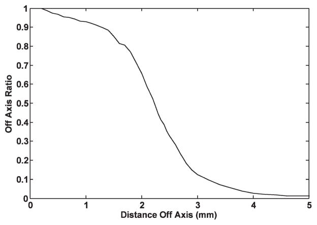
Previously, the Gamma Knife has been used to deliver intracranial radiation in a variety of small animal studies. However, in these studies the Gamma Knife treatment was planned using information from relatively low-resolution magnetic resonance (MR) or computed tomography (CT) imaging4 (7–13) or by using external measurements of the animal to locate an intracranial region of interest (14–18). Figure 1, the dose profile for the 4-mm Gamma Knife collimator, shows that the dose falls to 50% of the center-line dose at ~2 mm off axis and to 1% of the center-line dose at ~5 mm off axis. Gamma Knife focal irradiation of small animals, based on relatively low-resolution axial images or no images at all, is challenging because it is difficult to identify specific intracranial anatomical structures of interest as either targets or regions of avoidance. Thus an investigator may face limitations in taking full advantage of the small, well-defined Gamma Knife dose distribution. For example, the rat hippocampus covers ~5 mm in the lateral direction, ~2 mm in the superior-inferior direction, and ~3 mm along the third axis (19). Careful work and a well-detailed anatomical atlas of the rat brain enable clinical-sized CT- or MR-based Gamma Knife targeting of the rat brain hippocampus, such that the 4-mm collimator 50% isodose distribution covers the hippocampus in one hemisphere while sparing the contralateral hippocampal region. However, this type of focal irradiation plan could be much better executed with a high-resolution image of the rat brain that clearly shows the hippocampus and other relevant regions in stereotactic image space.
FIG. 1.
Ratio of focal point dose to off-axis dose used by Leksell Gamma Plan to calculate dose distributions for the 4-mm collimator. In general practice, dose is prescribed to the 50% isodose line, so in this case regions >2 mm from the focus would be considered to be out of the radiation field.
Low-resolution imaging typically has been used to plan Gamma Knife small animal irradiations because the Gamma Knife is designed to deliver stereotactic radiosurgery to human-sized subjects. This procedure is accomplished for a human subject by rigidly mounting a Leksell Model G headframe to the patient’s skull, then acquiring CT or MR imaging with a “localizer” box in place. The localizer box leaves fiducial marks on the images that are used to relate the image reference frame to the stereotactic coordinate frame used by the Leksell Gamma Plan (LGP) treatment planning software. The fiducial system defined by the human-sized localizer box is large (120 × 190 × 120 mm) compared to a small animal (e.g. 40-mm diameter for a rat) and requires a field of view (FOV) of at least 200 mm2 to encompass the fiducial marking system. Thus, to use the localizer box and commercial Gamma Knife planning software, the stereotactic image FOV must be about five times larger than the diameter of the animal, limiting the spatial resolution available for identifying features of interest such as the hippocampus in the small animal brain.
An alternative to large FOV imaging approaches, such as high-resolution 7T micro-MR, is capable of providing images that allow for the identification of features of interest in the rat brain. Figure 2 shows 3T MR and CT images acquired with FOVs large enough (FOV_CT = 320 mm2 and FOV_CT = 250 mm2) to include the Gamma Knife localizer box, as required for Gamma Knife treatment planning, alongside an image from a high-resolution 7T MR (FOV = 50 mm2). The benefit of 7T micro-MR compared to clinical-sized CT or MR in identification of the hippocampus and/or other structures in the rat brain is clearly illustrated in Fig. 2. However, the Gamma Knife localizer box does not fit in the 7T MR scanner aperture. Thus we have developed and validated a method to relate the 7T MR image coordinates to the Gamma Knife treatment planning coordinates, enabling 7T MR-based Gamma Knife focal irradiations to be performed.
FIG. 2.
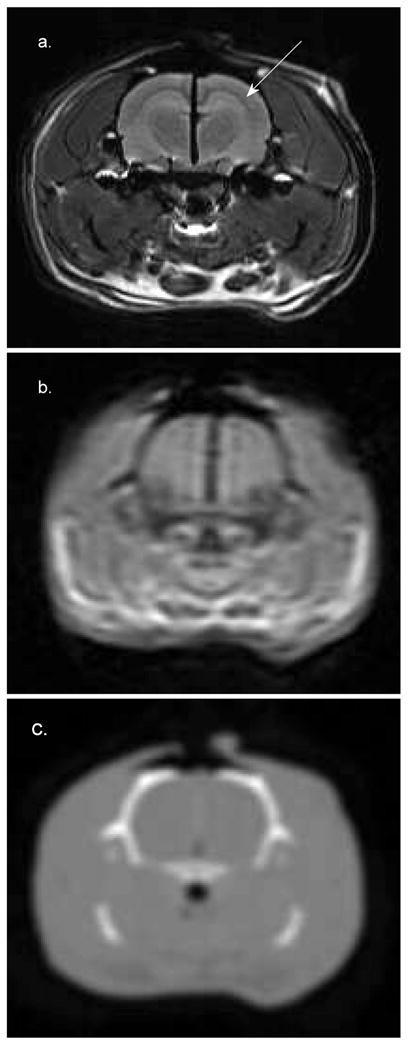
Cross section of the brain of a 19-week-old 546-g Sprague-Dawley rat. Panel a: 7T MR (FOV = 50 mm2). Panel b: 3T MR (FOV = 250 mm2). Panel c: CT (FOV = 320 mm2). The 7T image was acquired with an FOV large enough to include the surrogate fiducial system. The CT and 3T MR images were acquired with FOVs large enough to include the localizer box. These images were interpolated to a size comparable to the 7T image for comparison. The hippocampus is clearly visible in panel a (marked by the arrow) but cannot be identified in the other images. The dark line running in the vertical direction at midbrain in panels a and b is a piece of radiochromic film that was placed in the sagittal plane to verify the 7T Gamma Knife irradiation procedure.
This method uses a custom-made animal restraint and positioning jig with a scaled-down surrogate fiducial system, compatible with a small-bore 7T Bruker Biospin MR imaging system, and image transformation software that reads the surrogate fiducial marks on the restraint jig and writes geometrically correct Gamma Knife fiducial marks on the 7T MR images. With this approach 7T MR images can be used in the Gamma Knife planning software in the same fashion as clinical, stereotactic images. The following sections describe the techniques that are used to implement a Gamma Knife focal irradiation with high-resolution 7T micro-MR imaging and the validation of this process.
MATERIALS AND METHODS
Animal Restraint Jig and Surrogate Fiducial System
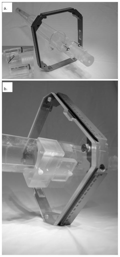
The restraint jig, shown in Fig. 3, is specifically designed to fit in the 72-mm dedicated rat imaging coil of the 7T Bruker BioSpin MRI. The jig is made from a 520-mm-long, 60-mm-inner-diameter acrylic tube. The top half of the tube is removed so that the animal can be set in the bottom of the tube in the prone position. A bite block and optional ear pins are used to reproducibly position the animal in the jig. The Gamma Knife headframe mounts to the jig approximately 60 mm from the bite block (the Gamma Knife headframe is removed before the jig is placed in the MRI).
FIG. 3.
Panel a: The animal restraint jig and surrogate fiducial system docked with the Gamma Knife headframe. The inset shows a close-up of the surrogate fiducial system. Panel b: The headframe is fixed to the acrylic mounting plate by four bolts. The headframe and mounting plate are fixed to the underside of the jig using an acrylic mounting bracket and two nylon screws to ensure that the headframe joins with the jig in the exact same manner every time. The frame, mounting plate and mounting bracket are removed for 7T MR imaging.
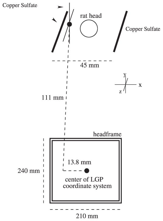
The surrogate fiducial system is fixed to the jig near the resting position for the animal’s head. The surrogate fiducial system consists of three acrylic blocks with milled channels that are filled with a 1% solution of copper sulfate, which appears bright on MR images. The two most lateral fiducial lines, 45 mm in separation, run parallel to the long axis of the jig and are used to correct for any rotation of the jig about its long axis (Fig. 4). Rotations of the jig inside the MR bore about the two other axes are prohibited by the tight fit of the jig within the bore. The intersection of the diagonal and vertical fiducial lines appears as a point on a single slice and is a known and fixed distance from the center of the Gamma Knife headframe. This intersection point is used to relate the image and LGP coordinate systems.
FIG. 4.
Schematic representation of the surrogate fiducial system. The two copper sulfate channels lateral to the rat’s head are used to correct for rotation. The intersection of the two copper sulfate channels to the left of the rat’s head creates the surrogate fiducial mark used to translate the LGP coordinate system to the image coordinate system. The lines that create the surrogate fiducial mark are ~1 mm in diameter, small enough that the intersection of the lines appears as a point on one slice when contiguous 1-mm-thick slices are acquired (1-mm, skip 0 MR scan protocol).
After the 7T images have been corrected for rotation about the long axis, the following transformation is determined to relate the surrogate fiducial system to the LGP coordinate system:
| (1) |
| (2) |
| (3) |
where XLGP, YLGP and ZLGP are the column, row and axial indices in image space, respectively, for the voxel located at the center of the LGP coordinate system. XMR, YMR and ZMR are the indices for the voxel containing the surrogate fiducial reference point. DX, DY and DZ are the known distances from the center of the LGP coordinate system to the surrogate fiducial point in the direction of the columns, rows and axis, respectively. VX, VY and VZ are the sizes of the voxels along the column, row and axis directions. Using the D and V variables that are known beforehand, and the variables denoted by the MR, which are found from the MR images, the LGP coordinate system can easily be mapped to the image frame.
Software Development
Leksell Gamma Plan fiducial marks that match the geometry of the CT and MR Gamma Knife localizer boxes are written on the 7T MR images using a custom program written in Matlab 2007a (Mathworks Inc., Natick, MA). Images in the DICOM format are read and displayed through a graphical user interface (GUI). The images are padded in the XY image plane to the size of the headframe to accommodate the calculated localizer box fiducial markers. Next, Z-axis image rotation is corrected. Each lateral fiducial mark is identified by clicking the cursor on the mark center. The software automatically calculates the angle of rotation and rotates the image set about the axis perpendicular to the image plane to correct for rotation in the MR bore.
After the images have been corrected for rotation, the location of the center of the LGP coordinate system in image space is calculated. First, the intersection of the diagonal and vertical fiducial lines is selected, and then the transform is calculated by Eqs. (1–3) using this point location, the voxel dimensions from the DICOM header, and the fixed distance from the surrogate fiducial mark to the center of the LGP coordinate system (equal to 13.8 mm in X, 0 in Y, and 11.1 mm in Z) (Fig. 4).
Once the center of the LGP coordinate system in image space is determined the LGP fiducial markers can be written onto the 7T MR image set at the correct locations, as if the images had been acquired with the Gamma Knife localizer box in place. The corners of the LGP fiducial system are drawn at offsets of 60 mm from XLGP and 95 mm from YLGP. The Z-location fiducial marks are added to each image based on the equations
| (4) |
| (5) |
where XAXIAL and YAXIAL are the voxel indices for the LGP axial fiducial marker for a particular image (i.e. particular location in Z), m is the number of voxels transversed in the Y direction per millimeter of travel in the Z direction, NZ is the slice index of the current image minus the slice index of ZLGP, and T is the thickness of a slice in millimeters. The images are then saved in DICOM format with the header modified to match the larger size of the padded images. The images are then sent to the LGP computer for treatment planning.
Validation
The above process was validated using a specially designed geometric phantom and a fresh rat cadaver. The geometric phantom was made from two 32-mm-diameter, 15-mm-long pieces of acrylic rod. Each half has two 3-mm holes oriented parallel to the central axes of the phantom that were filled with copper sulfate. These holes “dead-end” at the orthogonal surface of each half of the phantom. Carefully cut radiochromic film (Grafchromic MD-55, International Specialty Products, Wayne, NJ) was sandwiched between the two halves of the phantom, with the copper sulfate-filled holes intersecting the film plane. The phantom was secured in the jig and scanned in the 7T MR. Next, without moving the phantom, the headframe and localizer box were carefully fixed to the jig. The jig, headframe and localizer box underwent CT scanning (FOV = 320 mm2). The 7T MR images were coordinate-transformed offline and transmitted over the network to the LGP planning computer.
The 7T MR images were fused to the CT images in LGP by an image registration procedure to measure the agreement of the fiducial markers on the CT (from the clinical localizer box) against the artificial marks placed on the 7T MR images (obtained with the surrogate fiducial markers). Also, Gamma Knife shots were placed at the intersection of the radiochromic film and two of the copper sulfate-filled holes in the phantom using the 7T MR image set. The phantom was positioned manually in the Gamma Knife with a 4-mm collimator, and a dose of ~35 Gy (which exposed the film without saturation) was delivered to the two planned target locations.
A second validation study was performed using a fresh 546-g 19-week-old Sprague-Dawley rat corpse, under the auspices of a protocol approved by the Institutional Animal Care and Use Committee. The rat was killed humanely by overdose with sodium pentobarbital (200 mg/kg i.p.) and the skull was exposed. A midline craniotomy approximately 14 mm long and 2 mm wide was opened in the dorsal skull to expose the longitudinal fissure of the brain. A small rectangular piece of radiochromic film approximately 10 mm long and 7 mm tall and sealed in clear plastic for moisture protection was inserted at the midline between the hemispheres until the bottom edge of the film rested on the floor of the cranial cavity. A drop of cyanoacrylate glue was added to the upper edge to help hold the film in place, and the skin was sutured closed.
The rat was fixed in the jig and then underwent a 7T MR scan (FOV = 50 mm2, voxel size = 0.1953 × 0.1953 × 1 mm) with the surrogate fiducial system in place followed by CT (FOV = 320 mm2, voxel size = 0.625 × 0.625 × 1.25 mm) and 3T MR (FOV = 250 mm2, voxel size = 0.4883 × 0.4883 × 2 mm) scans with the headframe and standard Gamma Knife localizer box attached to the jig. The 7T MR images were transferred to an offline workstation where the LGP fiducial marks were added as described above. All image sets were sent to the LGP computer and co-registered to evaluate the accuracy of the surrogate fiducial marking process and thus the 7T-based Gamma Knife irradiations. A single 4-mm shot was planned on the radiochromic film in LGP using the 7T MR images for planning, the coordinates were set manually, and a dose of ~35 Gy was delivered to the target centered on the film. Thus this experiment tested the 7T MR-based Gamma Knife irradiation procedure through all phases of image acquisition, treatment planning and delivery of focal radiation.
All 7T MR images used in this work were acquired with a 72-mm birdcage coil for signal excitation and reception (Bruker BioSpin). Conventional T2-weighted Rapid Acquisition with Relaxation Enhancement (RARE) images (TE = 50 ms, TR = 3000 ms) were acquired in the axial orientation.
RESULTS
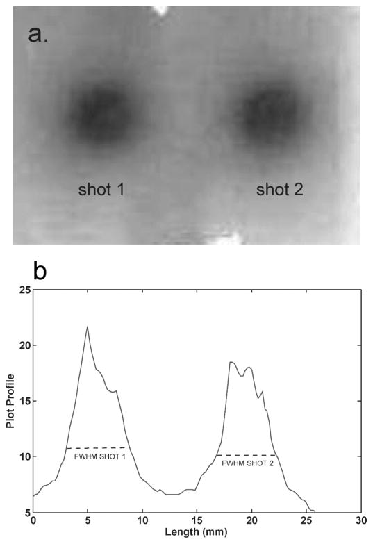
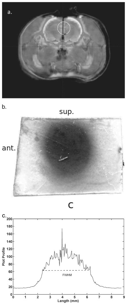
The LGP software produced a fused CT-7T image set with phantom structures that agreed to within one voxel at all points. The irradiated radiochromic film is shown in Fig. 5. The full width at half maximum (FWHM) of each shot was 5.4 mm, which shows that the shot with the 4-mm collimator was centered along the Z direction. The centers of the shots, found from the FWHMs, were separated by 14.0 mm, which agrees with the physical dimensions of the geometric phantom to <0.1 mm.
FIG. 5.
Panel a: The exposed film used in the geometric phantom. Panel b: Plot profile through the horizontal axis of the film. The full width at half maximum (FWHM) of each shot was 5.4 mm, which shows that the center of the shot was well located by the LGP plan using the 7T image set. The centers of the two shots, as indicated by the FWHM, were separated by 14 mm, which is in exact agreement with the physical separation of the copper sulfate filled channels.
Analysis of an image of the exposed film fixed on the geometric phantom showed that the center of shot number 1 (lower shot) agreed within one voxel (<0.3 mm) to the center of the copper sulfate channel. Shot number 2 (upper shot) was off-centered approximately 0.3 mm (~1 voxel) in X and Y compared to its copper sulfate channel. This small offset may have occurred due to a slight error in targeting at the time of the stereotactic treatment planning because of an adhesive residue in the hole, an artifact of manufacturing. Using the LGP treatment plan based on the 7T image set, we were able to deliver two Gamma Knife shots to the phantom that were localized to ~0.3 mm along each axis.
The 7T MR images of the rat cadaver were registered to the 3T and CT images in LGP as described above. The registration was evaluated visually by comparing image features that were easily and mutually distinguishable on both image sets. Features generally agreed to within two voxels for the registrations, and all structure volumes on the 7T images fell inside the CT and 3T MR image volumes. Comparison among the image sets was made difficult at times due to partial volume effects on the CT and 3T image sets that made it hard to determine the edges of certain structures on these images, which further emphasizes the superior ability of 7T images to distinguish structures of interest in the rat brain.
Figure 6 shows the film from the midline sagittal plane of the cadaver rat brain and the LGP plan used to target the shot on the film. The FWHM of the shot was 5.1 mm, which indicates that the shot was well centered along the X axis. The shot was centered 4.5 mm above the inferior edge of the film and six 1-mm slices from the anterior edge of the film (which means the center of the exposed shot should be between 4–6 mm from the anterior edge) in the LGP plan using the 7T image set. The exposure on the film was 4.5 mm from the inferior edge of the film, showing that the shot was centered to < 0.1 mm in the Y direction, and 5.2 mm from the anterior edge, showing good agreement with the LGP plan.
FIG. 6.
Panel a: Fusion of the 7T MR and CT images that was used to target the shot on the film in the cadaver rat brain. The centers of volume of specific features, such as bone and brain, agree to <2 voxels in all places. Panel b: The exposed film, which had been oriented in the animal such that the left side of the film (in the figure) was the anterior edge inside the animal and the top of the film was the superior edge. The LGP plan in panel a shows that the center of the shot was placed 4.5 mm from the inferior edge of the film. The measured distance from the inferior edge of the exposed film to the center of the shot, as indicated by the FWHM, was 4.5 mm. This shows that the shot was localized in the superior-inferior direction to <0.1 mm by the 7T LGP plan. Panel c: A profile through the horizontal axis of the exposed film. The FWHM was 5.1 mm, which shows that the shot was well centered along the X axis.
DISCUSSION
This work shows that high-resolution small-bore microimaging modalities (in this work micro-MR was studied, but the technique is applicable for micro-CT or micro-PET) can be incorporated into the Gamma Knife treatment planning process through the use of surrogate fiducial markers and image transformation. The surrogate fiducial method produces excellent agreement with the standard Gamma Knife fiducial marks to within 1 voxel for the 7T micro-MR images, or approximately 0.3 mm. The high-resolution 7T micro-MR allows one to identify anatomical structures in the rat brain that are not discernible in the 3T MR or the CT images (with a human-sized FOV large enough to include the Gamma Knife localizer box). Thus high-resolution 7T micro-MR imaging for Gamma Knife treatment planning allows for sub-millimeter precision for Gamma Knife irradiation of targets of interest in the rat brain.
The ability to accurately target specific structures in the brain for preclinical studies with the Gamma Knife is becoming increasingly important as the use of techniques such as Gamma Knife stereotactic radiosurgery, IMRT and robotically controlled systems (e.g. Cyberknife, Accuray Inc., Sunnyvale, CA) becomes more common in the clinic. These approaches all use multiple beams to deliver radiosurgical or hypofractionated conformal doses of radiation to intra- and extracranial sites of disease. With the technical capabilities for delivery of these highly conformal doses comes the need for a better understanding of the underlying biological mechanisms that govern the response to these treatments. Preclinical studies to evaluate the biological effects of hypofractionated high-dose radiotherapy treatments as well as studies to look at the biological effects of multiple low-dose entrance and exit beams are needed to better understand the effects of this highly conformal radiotherapy. The work reported here has been performed to enable better focal radiation targeting and analysis of radiation response for specific intracranial regions of the rat.
Acknowledgments
This work was supported by the TRADONC Program, Wake Forest University School of Medicine (NCI T-32 CA113267), and a grant from the Kulynych Interdisciplinary Research Fund, Intramural Research Committee, Wake Forest University School of Medicine (GTS no. 33697).
Footnotes
T. Atwood, Bioanatomic MRI of Brain Tumors in Animal Models: Implications for Radiation Therapy Treatment Planning and Assessment of Treatment Response. Dissertation, Wake Forest University, 2008.
References
- 1.Sanghani M, Mignano J. Intensity modulated radiation therapy: A review of current practices and future directions. Technol Cancer Res Treat. 2006;5:447. doi: 10.1177/153303460600500501. [DOI] [PubMed] [Google Scholar]
- 2.Wong J, Armour E, Kazanzides P, Iordachita I, Tryggestad E, Deng H, Matinfar M, Kennedy C, Liu Z, DeWeese TL. High-resolution, small animal radiation research platform with x-ray tomographic guidance capabilities. Int J Radiat Oncol Biol Phys. 2008;71:1591–1599. doi: 10.1016/j.ijrobp.2008.04.025. [DOI] [PMC free article] [PubMed] [Google Scholar]
- 3.Wang S, Liu Z, Sultana S, Schreiber E, Zhou O, Chang S. A novel high resolution micro-radiotherapy system for small animal irradiation for cancer research. Biofactors. 2007;30:265–270. doi: 10.1002/biof.5520300408. [DOI] [PubMed] [Google Scholar]
- 4.Lindsay P, Ansell S, Moseley D, Jelveh S, Hill R, Jaffray D. Development of an image-guided conformal small animal irradiation platform. Med Phys. 2008;35:2695. [Google Scholar]
- 5.Stojadinovic S, Low DA, Hope AJ, Vicic M, Deasy JO, Cui J, Khullar D, Parikh PJ, Malinowski KT, Grigsby PW. MicroRT small animal conformal irradiator. Med Phys. 2007;34:4706–4716. doi: 10.1118/1.2799887. [DOI] [PubMed] [Google Scholar]
- 6.Graves EE, Zhou H, Chatterjee R, Keall PJ, Gambhir SS, Contag CH, Boyer AL. Design and evaluation of a variable aperture collimator for conformal radiotherapy of small animals using a microCT scanner. Med Phys. 2007;34:4359–4367. doi: 10.1118/1.2789498. [DOI] [PubMed] [Google Scholar]
- 7.Liang C, Li W, Liu N, Yin Y, Hao J, Zhao W. Effects of Gamma Knife irradiation in the expression of NMDA receptor subunits in rat forebrain. Neurosci Lett. 2008;439:250–255. doi: 10.1016/j.neulet.2008.05.046. [DOI] [PubMed] [Google Scholar]
- 8.Jirak D, Namestkova K, Herynek V, Liscak R, Vymazal J, Mares V, Sykova E, Hajek M. Lesion evolution after Gamma Knife irradiation observed by magnetic resonance imaging. Int J Radiat Biol. 2007;83:237–244. doi: 10.1080/09553000601169792. [DOI] [PubMed] [Google Scholar]
- 9.Tokumaru O, Tomhida M, Katayama Y, Hayashi M, Kawakimi Y, Kouyana N. The effect of Gamma Knife irradiation on functions of striatum in rats. J Neurosurg. 2005;102(Suppl):42–48. doi: 10.3171/jns.2005.102.s_supplement.0042. [DOI] [PubMed] [Google Scholar]
- 10.Herynek V, Burian M, Jirak D, Liscak R, Namestkova K, Hajek M, Sykova E. Metabolite and diffusion changes in the rat brain after Leksell Gamma Knife irradiation. Magn Reson Med. 2004;52:397–402. doi: 10.1002/mrm.20150. [DOI] [PubMed] [Google Scholar]
- 11.Liscak R, Vladyka V, Novotny J, Brozek G, Namestkova N, Mares V, Herynek V, Jirak D, Hajek M, Sykova E. Leksell Gamma Knife lesioning of the rat hippocampus: the relationship between radiation dose and functional and structural damage. J Neurosurg. 2002;97(Suppl):666–673. doi: 10.3171/jns.2002.97.supplement. [DOI] [PubMed] [Google Scholar]
- 12.Rao ZR, Ge X, Qiou JY, Yang T, Duan L, Ju G. Expression and changes of HSP70 in the rat forebrain subjected to Gamma Knife (100 Gy) irradiation targeted in the caudate putamen and survived for different times. Neurosci Res. 2000;38:139–146. doi: 10.1016/s0168-0102(00)00134-6. [DOI] [PubMed] [Google Scholar]
- 13.Duan XQ, Wu SL, Li T, Liang JC, Qiou JY, Rao ZR, Ju G. Expression and significance of three types of Fos-immunoreactive cells after Gamma Knife irradiation of the forebrain in the rat. Neurosci Res. 1999;33:99–104. doi: 10.1016/s0168-0102(98)00124-2. [DOI] [PubMed] [Google Scholar]
- 14.Lee JI, Itasaka S, Kim JT, Nam DH. Antiangiogenic agent, thalidomide increases the antitumor effect of single high dose irradiation (Gamma Knife radiosurgery) in the rat orthotopic glioma model. Oncol Rep. 2006;15:1163–1168. [PubMed] [Google Scholar]
- 15.Kamiryo T, Berk HW, Lee KS, Kassell NF, Steiner L. A stereotactic device for experimental Gamma Knife radiosurgery in rats. Acta Neurochir (Wien) 1993;125:156–160. doi: 10.1007/BF01401844. [DOI] [PubMed] [Google Scholar]
- 16.Chen ZF, Kamiryo T, Henson SL, Yamamoto H, Bertram EH, Schottler F, Patel F, Steiner L, Prasad D, Lee KS. Anticonvulsant effects of gamma surgery in a model of chronic spontaneous limbic epilepsy in rats. J Nerosurg. 2001;94:270–280. doi: 10.3171/jns.2001.94.2.0270. [DOI] [PubMed] [Google Scholar]
- 17.Kamiryo T, Berr SS, Berk HW, Lee KS, Kassell NF, Steiner L. Accuracy of an experimental stereotactic system for MRI-based Gamma Knife irradiation in the rat. Acta Neurochir (Wien) 1996;138:1103–1108. doi: 10.1007/BF01412315. [DOI] [PubMed] [Google Scholar]
- 18.Kamiryo T, Berr SS, Lee KS, Kassell NF, Steiner L. Enhanced magnetic resonance imaging of the rat brain using a stereotactic device with a small head coil. Acta Neurochir (Wien) 1995;133:87–92. doi: 10.1007/BF01404955. [DOI] [PubMed] [Google Scholar]
- 19.Paxinos G, Watson C. The Rat Brain in Stereotactic Coordinates. Elsevier Academic Press; Burlington: 2005. [Google Scholar]


