Abstract
A series of 2-phenoxypyridyl and 2-phenoxyimino ligands, H2LR,R’ (2,2’-(5,5’-(1,2-phenylenebis(ethyne-2,1-diyl))bis(pyridine-5,2-diyl))diphenol, where R = H, Me, or t-Bu, and R’ = H, or Ph) and H2BIPSMe,Ph ((3,3’-(1E,1’E)-(3,3’-sulfonylbis(3,1-phenylene)bis(azan-1-yl-1-ylidene))bis(methan-1-yl-1-ylidene)bis(5-methylbiphenyl-2-ol)) were synthesized as platforms for non-heme diiron(II) protein model complexes. UV-vis spectrophotometric studies and preparative-scale reactions of LR,R’ or BIPSMe,Ph, where LR,R’ and BIPSMe,Ph are the deprotonated forms of H2LR,R’ and H2BIPSMe,Ph, respectively, with Fe(II) revealed that the presence of sterically protective ortho phenol substituents is necessary to obtain discrete dinuclear species. Reaction of LMe,Ph with Fe(II) in THF afforded the doubly-bridged compound [Fe2(LMe,Ph)2(THF)3] (1), which was characterized in the solid state by X-ray crystallography. A large internal cavity in this complex facilitates its rapid reaction with dioxygen, even at −50 °C, to produce the thermodynamically stable [Fe2(μ-O)(LMe,Ph)2] (2) species. Reaction of 18O2 instead of 16O2 with 1 led to a shift in the Fe–O–Fe vibrational frequency from 833 cm-1 to 798 cm-1, confirming the presence of the μ-oxodiiron(III) core and molecular oxygen as the source of the bridging oxo group. The LMe,Ph ligand is robust toward oxidative decomposition and does not display any reversible redox activity.
Introduction
Our laboratory has a longstanding interest in developing synthetic analogs of iron-containing proteins that activate molecular oxygen.1-3 The goal of our investigations is two-fold, namely, to understand the structural and electronic features that control dioxygen activation in biological systems and to construct potent oxidation catalysts that utilize molecular oxygen as an environmentally friendly and economically viable chemical feedstock. Our efforts have been largely inspired by the bacterial multi-component monooxygenase (BMM) family of enzymes.4-6 These multicomponent systems, which include soluble methane monooxygenase (sMMO),4 phenol hydroxylase (PH),7 and toluene/o-xylene monooxygenase (ToMO),7,8 perform oxygen-atom transfer reactions in aerobic environments under mild conditions. Although substrate oxidation is believed to occur at the diiron centers of the hydroxylase component, the BMM machinery also requires both reductase and regulatory proteins to function efficiently. Attempts to mimic monooxygenase activity in synthetic systems have led to the preparation of a rich assortment of diiron compounds that display structural, spectroscopic, and/or functional features similar to those of the protein active sites.9-12 To date, however, no diiron model complexes have been able to match the biological systems in terms of catalytic efficiency, chemoselectivity, and oxygenation ability.13
To overcome the shortcomings of existing diiron model designs, our strategy has been to construct diiron complexes with organic ligands that more accurately resemble the primary coordination spheres of the BMM hydroxylase active sites. The structure of each diiron protein core comprises four carboxylate amino acid side chains, two histidine imidazole groups syn to the Fe–Fe vector, and an internal O2-binding cavity.14-16 A representative view of the reduced form of soluble methane monooxygenase hydroxylase (sMMOHred) is provided in Chart 1 (left). To achieve such an architecture in a small-molecule host, we have synthesized dinucleating ligands derived from 1,2- diethynylbenzene moieties.17,18 Our studies with this class of ligands have resulted in the preparation of several dinuclear compounds, most notably with 8-carboxy ester quinoline17 and 2-carboxy ester pyridyl19 metal-binding groups. These dimetallic complexes, however, are substitutionally labile and readily dissociate upon exposure to dioxygen. To obtain a more kinetically stable platform, we wished to introduce 2-phenoxypyridyl moieties into the 1,2-diethynylbenzene backbone. Although the diiron sites in BMM hydroxylases do not contain phenolate donors, iron-bound tyrosinate ligands occur in the O2-activating enzymes intradiol dioxygenases20,21 and the phosphate ester hydrolyzing proteins mammalian purple acid phosphatases.22 Incorporating phenol rings into the ligand framework also facilitates synthetic modifications, such as appending bulky moieties for steric protection or introducing electron-donating/or -withdrawing groups for electronic tuning. Our initial synthetic target based on the 2-phenoxypyridyl dinucleating motif is shown in Chart 1 (right). In this design, the exogenous carboxylates are unrestrained so that the diiron complex could accommodate structural rearrangements upon reaction with dioxygen.
Chart 1.
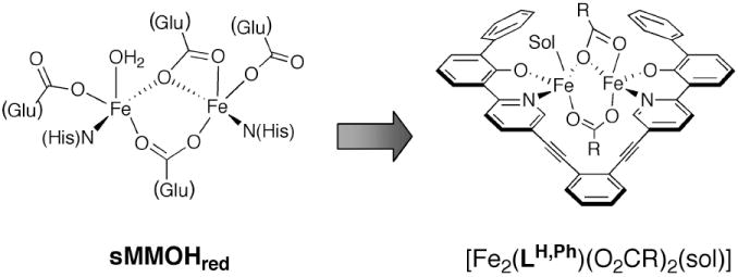
Active site structure of reduced soluble methane monooxygenase hydroxylase (sMMOHred, left) and a proposed synthetic analog with a dinucleating ligand, LH,Ph (right), containing a 2-phenoxypyridyl group. Sol = solvent molecule.
In the present paper we report the results of a systematic study of the coordination chemistry of a new family of 2-phenoxypyridyl and 2-phenoxyimino ligands with iron(II). The importance of incorporating sterically protecting groups to the ligand periphery and its implication for future ligand designs are discussed. This work led to the synthesis of a diiron(II) complex which, although it did not yield the target structure in Chart 1, was of considerable interest in its own right, reacting rapidly with dioxygen and demonstrating potential as a substrate oxidation catalyst.
Experimental Section
Materials and Methods
Reagents were obtained from Strem, Aldrich Chemical Co., and Alfa Aesar and used as received. The synthesis and characterization of all organic ligand precursors are described in the Supporting Information. The iron(II) starting material [Fe2(Mes)4] (where Mes = 2,4,6-trimethylphenyl) was prepared according to a literature procedure.23 Air-sensitive manipulations were performed using standard Schlenk techniques or under a nitrogen atmosphere inside a MBraun drybox. All solvents were saturated with argon and purified by passage over two columns of activated Al2O3. Labeled dioxygen (~ 98% 18O2) was obtained from Isotech and used without further purification.
General Physical Methods
NMR spectra were recorded on a 500 MHz Varian Mercury spectrometer and chemical shifts for 1H and 13C spectra were referenced to residual solvent peaks. IR spectra were recorded on a ThermoNicolet Avatar 360 spectrophotometer with OMNIC software. Absorption spectra were recorded on a Cary 50 spectrophotometer using 6Q Spectrosil quartz cuvettes (Starna) with 1 cm path lengths. Cyclic voltammetry and differential pulse voltammetry measurements were made using a VersaSTAT3 potentiostat from Princeton Applied Research using the V3 Studio software. Electrospray ionization mass spectra were acquired on an Agilent Technologies 1100 Series LC-MSD Trap. Gas-chromatographic mass spectra were obtained using an Agilent Technologies 6890 N GC system equipped with a 5973N MSD unit.
X-ray Collection and Data Refinement
Single crystals were mounted in Paratone oil on a cryo-loop and frozen under a 110 K KRYO-FLEX nitrogen cold stream. Data were collected on a Bruker APEX CCD X-ray diffractometer with Mo Kα radiation (λ = 0.71073 Å) controlled by the SMART software package.24 Empirical absorption corrections were applied using SADABS.25 The structure was solved by Patterson methods with refinement by full-matrix least squares based on F2 using the SHELXTL-97 software package.26 All non-hydrogen atoms were located and refined anisotropically. Hydrogen atoms were assigned idealized positions based on a riding model. Additional crystallographic details are provided in the Supporting Information.
57Fe Mössbauer Spectroscopy
Mössbauer spectra were recorded on a MSI spectrometer (WEB Research Company) with a 57Co source in a Rh matrix maintained at room temperature. Solid samples were prepared by suspending in Apiezon M grease and placed in a nylon sample holder. Data were acquired at 90 K, and the isomer shift (δ) values are reported with respect to metallic iron that was used for velocity calibration at room temperature. The spectra were fit to Lorentzian lines using the WMOSS plot and fit program (WEB Research, Minneapolis).
Stopped-flow UV-vis spectrophotometry
Ambient-pressure kinetic studies were performed using a Canterbury SF-41 stopped-flow instrument (Hi-Tech) and a fused-silica fiber optics spectrometer (Oriel Corp.). Data were acquired using a KinetAsyst v. 3.16 software (TgK Scientific Limited) at a sampling rate of 300 scans in 30 s. To avoid moisture and pre-oxidation, the stainless-steel lines were washed with dioxygen-free anyhydrous THF before loading the sample syringes. The mixing cell was maintained at -50.0 ± 0.1 °C. Before mixing, the concentration of complex 1 was 26 μM in THF and that of the dioxygen solution was assumed to be 10 mM.27
Synthesis
H2LVH,H (2,2’-(5,5’-(4,5-dimethoxy-1,2-phenylene)bis(ethyne-2,1-diyl)bis(pyridine-5,2-diyl)) diphenol)
Solid Benz2LVH,H (5,5’-(4,5-dimethoxy-1,2-phenylene)bis(ethyne-2,1-diyl)bis(2-(2-(benzyloxy)phenyl)pyridine)) (46.0 mg, 65.3 μmol) and iodotrimethylsilane (0.02 mL, 163 μmol) were combined in 2 mL of dry CH2Cl2 in a 10 mL Schlenk flask. The reaction mixture was stirred at RT for 22 h. A diluted solution of HCl(aq) was added and the organic phase was extracted with CH2Cl2. The organic layer was separated, dried over Na2SO4, filtered, and evaporated to dryness. The crude material was purified by silica gel column chromatography (CH2Cl2) to afford a yellow solid (10 mg, 29%). 1H NMR (CDCl3, 500 MHz): δ 8.70 (s, 2H), 7.95 (d, J = 2.0 Hz, 4H), 7.80 (dd, J = 9.5, 1.5 Hz, 2H), 7.34 (t, J = 8.5 Hz, 2H), 7.08-7.04 (m, 4H). 6.93 (t, J = 8.5 Hz, 2H), 3.98 (s, 6H). ESI-MS = 525.3 [M+H]+. Mp = 166-167 °C.
H2LH,H (2,2’-(5,5’-(1,2-phenylenebis(ethyne-2,1-diyl))bis(pyridine-5,2-diyl))diphenol)
Solid Me2LVH,H (1,2-bis((6-(2-methoxyphenyl)pyridin-3-yl)ethynyl)benzene) (340 mg, 0.690 mmol) was dissolved in 15 mL of dry CH2Cl2 and cooled to -78°C. A 1.0 M CH2Cl2 solution of BBr3 (3.4 mL, 3.45 mmol) was added slowly to the reaction mixture and stirred for 6 h at 0 °C. The reaction was quenched with trifluoroacetic acid (2 mL) and washed with K2CO3 (aq). The organic layer was separated, dried over Na2SO4, filtered, and evaporated to dryness. Purification of the crude material by silica gel column chromatography (20:80 EtOAc/Hexanes) gave a yellow solid (122 mg, 38%). 1H NMR (CDCl3, 500 MHz): δ 13.41 (bs, 2H), 10.40 (s, 2H), 9.77-9.68 (m, 4H), 9.53 (d, J = 8.0 Hz, 2H), 9.27 (s, 2H), 9.05 (s, 2H), 8.88 (t, J = 7.0 Hz, 2H), 8.54-8.48 (m, 4H). 13C NMR (CDCl3, 500 MHz): δ 161.47, 158.28, 149.50, 141.05, 133.09, 132.72, 129.84, 127.62, 126.02, 120.01, 119.57, 119.44, 119.39, 118.72, 92.52, 90.93. ESI-MS = 465.3 [M+H]+. Mp = 141-145 °C.
H2LH,Ph (3,3’-(5,5’-(1,2-phenylenebis(ethyne-2,1-diyl))bis(pyridine-5,2-diyl))dibiphenyl-2-ol)
The foregoing procedure was employed except that Me2LH,Ph (1,2-bis((6-(2-methoxybiphenyl-3-yl)pyridin-3-yl)ethynyl)benzene) was used in place of Me2LH,H. The reaction was performed using Me2LH,Ph (1.50 g, 2.32 mmol) and 1.0 M BBr3 in CH2Cl2 (12 mL, 12 mmol). Purification of the crude material by silica gel column chromatography (20:80 THF/hexanes) gave a yellow solid (393 mg, 27%). 1H NMR (CDCl3, 500 MHz): δ 14.50 (bs, 2H), 8.66 (s, 2H), 8.00-7.95 (m, 4H), 7.82 (d, J = 8.0 Hz, 2H), 7.66-7.61 (m, 6H), 7.47-7.34 (m, 10H), 7.00 (t, J = 8.0 Hz, 2H). 13C NMR (CDCl3, 500 MHz): δ 157.60, 157.22, 148.33, 140.07, 138.57, 133.35, 132.34, 131.57, 129.69, 129.03, 128.25, 127.23, 126.06, 125.19, 119.31, 119.06, 118.68, 118.10, 92.33, 90.04. ESI-MS = 617.4 [M+H]+. Mp = 104-106 °C.
H2LMe,Ph (3,3’-(5,5’-(1,2-phenylenebis(ethyne-2,1-diyl))bis(pyridine-5,2-diyl))bis(5-methyl-bi phenyl-2-ol)
Method A: Solid Benz2LMe,Ph (1,2-bis((6-(2-(benzyloxy)-5-methylbiphenyl-3-yl)pyridin-3-yl)ethynyl)benzene) (1.20 g, 1.45 mmol) and iodotrimethylsilane (2.1 mL, 14.9 mmol) were combined in 50 mL of dry toluene and stirred in a sealed reaction vessel at 130 °C for 3 d. Dilute HCl (aq) was added to quench the reaction and the organic phase was extracted with CH2Cl2 (3 × 30 mL). The organic layer was separated, dried over Na2SO4, filtered, and evaporated to dryness. Purification of the crude material by silica gel column chromatography (50:50 hexanes/CH2Cl2) gave a yellow solid (630 mg, 67%). Method B: Solid Benz2LMe,Ph (1.65 g, 2.00 mmol) was dissolved in CH2Cl2 (75 mL) and cooled to -78°C. A 1.0 M BBr3 solution in CH2Cl2 (4.40 mL, 4.40 mmol) was added dropwise into the reaction flask. After stirring for 2 h, the mixture was quenched with H2O (100 mL). The organic product was extracted with CH2Cl2 (3 × 50 mL), dried over Na2SO4, filtered, and evaporated to afford an oil. About 50 mL of CH3OH was added to the residue and a large amount of yellow solid appeared after 1 h. The product was isolated by filtration and re-crystallized form hot CH2Cl2/CH3OH to give the desired material (0.99 g, 78 %). 1H NMR (CDCl3, 500 MHz): δ 14.38 (bs, 2H), 8.64 (s, 2H), 7.95 (dd, J = 8.5 Hz, 4H), 7.68-7.61 (m, 8H), 7.48-7.35 (m, 8H), 7.35 (s, 2H), 2.40 (d, 6H). 13C NMR (CDCl3, 500 MHz): δ 155.31, 148.30, 139.94, 138.65, 134.28, 132.28, 131.23, 129.64, 128.96, 128.21, 127.89, 127.15, 126.20, 125.15, 119.24, 118.30, 117.89, 92.26, 90.09, 20.96. ESI-MS = 645.4 [M+H]+. Mp = 137-140 °C.
H2LtBu,Ph (3,3’-(5,5’-(1,2-phenylenebis(ethyne-2,1-diyl))bis(pyridine-5,2-diyl))bis(5-tert-butylbi phenyl-2-ol))
The same procedure was employed as for the synthesis of H2LMe,Ph (Method A), except that Benz2LtBu,Ph (1,2-bis((6-(2-(benzyloxy)-5-tert-butylbiphenyl-3-yl)pyridin-3-yl)ethynyl)benzene) was used instead of Benz2LMe,Ph. The reaction was performed with Benz2LtBu,Ph (260 mg, 0.286 mmol) and iodotrimethylsilane (0.4 mL, 2.86 mmol). Purification of the crude material by silica gel column chromatography (50:50 CH2Cl2/Hexanes) gave a yellow solid (43 mg, 21%). 1H NMR (CDCl3, 500 MHz): δ 14.39 (bs, 2H), 8.68 (d, 2.5 Hz, 2H), 8.93 (d, J = 8.5 Hz, 2H), 7.97 (dd, J = 10.5, 2.0 Hz, 2H), 7.83 (d, J = 2.5 Hz, 2H), 7.69-7.68 (m, 4H), 7.65-7.63 (m, 2H), 7.50-7.47 (m, 6H), 7.41-7.37 (m, 4H), 1.42 (s, 18H). 13C NMR (CDCl3, 500 MHz): δ 157.54, 155.28, 148.46, 141.42, 139.93, 139.07, 132.35, 131.08, 130.98, 129.73, 128.98, 128.24, 127.14, 125.14, 122.39, 119.21, 117.86, 117.85, 92.21, 90.12, 34.49, 21.77. ESI-MS = 729.5 [M+H]+. Mp = 125-128 °C.
H2BIPSMe,Ph (3,3’-(1E,1’E)-(3,3’-sulfonylbis(3,1-phenylene)bis(azan-1-yl-1-ylidene))bis(methan-1-yl-1-ylidene)bis(5-methylbiphenyl-2-ol))
In a 100 mL round-bottom flask, 2-hydroxy-5-methyl-3-phenylbenzaldehyde (11) (2.60 g, 12.3 mmol) and 3,3’-diaminodiphenylsulfone (1.38 g, 5.56 mmol) were dissolved in 50 mL of MeOH. The mixture was treated with formic acid (0.46 mL, 12.3 mmol) and stirred at room temperature for 5 h. The resulting bright orange precipitate was isolated by filtration and washed with MeOH. Purification of the reaction product by silica gel column chromatography (CH2Cl2 → 15% EtOAc/CH2Cl2) gave the desired product (2.1 g, 48 %). A small amount of the starting aldehyde and singly condensed product (< 2 %) were still present in the purified material, presumably due to hydrolysis of H2BIPSMe,Ph. 1H NMR (CDCl3, 500 MHz): δ 13.19 (s, 2H), 8.59 (s, 2H), 7.88 (m, 2H), 7.61-7.57 (m, 6H), 7.47-7.44 (m, 4H), 7.38-7.24 (m, 6 H), 2.38 (s, 6H). 13C NMR (CDCl3, 500 MHz): δ 164.97, 156.52, 149.62, 142.86, 137.58, 136.23, 132.41, 130.84, 130.18, 129.47, 126.68, 128.37, 127.48, 126.99, 125.88, 119.99, 118.88, 20.61. ESI-MS = 637.2 [M+H]+. Mp = 141-145 °C.
[Fe2(LMe, Ph)2(THF)3] (1)
Inside a drybox, solid H2LMe,Ph (200 mg, 310 μmol) and [Fe2(Mes)4] (91.3 mg, 155 μmol) were dissolved in 10 mL of THF in a 25 mL flask to give a dark red solution. The mixture was stirred at RT for 10 min and the solvent was removed in vacuo. A solution of Et2O (10 mL) was added and the resulting suspension was stirred for 10 min. The solid material was isolated by filtration and crystallized by layering pentane (2 mL) onto a solution of the compound in THF (10 mL). Upon drying, the dark red crystals became a red-brown powder (116 mg, 46 %). Crystals suitable for X-ray diffraction studies were obtained by vapor diffusion of pentane into a solution of the complex in THF. 1H NMR (THF-d8, 500 MHz): δ = 44.45 (bs), 42.20 (bs), 38.08 (bs), 36.30 (bs), 34.14 (bs, methyl), 11.01 (bs), 6.84 (bs), 6.25 (bs), 5.61 (bs), 4.61 (bs). IR (KBr): v = 3442, 2918, 2851, 1595, 1555, 1495, 1453, 1420, 1368, 1292, 1250, 1222, 1045, 840, 821, 757, 698 cm-1. λmax = 395 (ε = 5130 M-1 cm-1), 332 (ε = 63,300 M-1 cm-1), 306 (ε = 94100 M-1 cm-1), 235 (ε = 137000 M-1 cm-1) nm. 57Fe Mössbauer (90 K): δ = 1.13 mm/s, ΔEQ = 1.88 mm/s, ΓL/R = 0.47 mm/s. Mp > 400 °C. Anal. Calc. for 1, Fe2C104H84N4O7: C, 77.42; H, 5.25; N, 3.47. Found: C, 76.66, 76.91; H, 4.50, 4.22; N, 4.16, 4.65. Drying of the samples under vacuum at 80 °C and repeated measurements of independently prepared material gave similar results. Deviations between calculated and observed values are ascribed to residual solvent molecules and possibly partial oxidation to form 2 since 1 is quite air-sensitive. Because we have crystal structure information on 1, which has disordered THF and pentane in the crystal lattice, and the crystalline samples looked identical with copious amounts of material, there is no doubt about the composition of 1.
[Fe2(μ-O)(LMe, Ph)2] (2)
Method A. The [Fe2(LMe, Ph)2(THF)3] complex (50 mg, 31 mmol) was dissolved in THF (2 mL) in a 5 mL Schlenk flask under a nitrogen atmosphere. An excess amount of dry O2 gas was introduced and the reaction was stirred for 5 min. The solvent mixture was evaporated to dryness and the resulting dark red residue was extracted into dry toluene (2 mL). The desired material was crystallized from vapor diffusion of pentane into a solution of the complex in toluene to give a dark red material (35 mg, 80%). Method B. The dinucleating ligand H2LMe,Ph (137 mg, 213 μmol) and NaHMDS (82 mg, 447 μmol) were dissolved in THF (3 mL) to give a bright orange solution. A solution of (NEt4)2[Fe2OCl6] (141 mg, 234 μmol) in CH3CN (0.5 mL) was added and the dark red mixture was stirred for 15 min. The solvent was removed in vacuo and the resulting product was extracted into toluene. Evaporation of the toluene solution gave the desired complex as a red solid (70 mg, 47 %). Crystals suitable for X-ray diffraction studies were obtained by vapor diffusion of pentane into a solution of the complex in THF. 1H NMR (THF-d8, 500 MHz): δ = 16.42 (bs), 13.90 (bs), 11.75 (bs), 8.56 (bs), 8.25 (bs), 7.59 (bs), 7.52 (bs), 6.96 (bs), 6.60 (bs). IR (KBr): v = 3431, 3030, 2917, 2851, 1598, 1493, 1418, 1367, 1290, 1250, 1225, 833, 758, 697 cm-1. λmax = 390 (sh, ε = 37,500 M-1 cm-1), 312 (ε = 108,000 M-1 cm-1) nm. 57Fe Mössbauer (90K): δ = 0.43 mm/s, ΔEQ = 1.35 mm/s, ΓL/R = 0.42 mm/s. Mp = 335°C (decomposition). Anal. Calc. for 2·4THF, Fe2C108H92N4O9: C, 76.96; H, 5.50; N, 3.33. Found: C, 76.23; H, 5.45; N, 3.29. This result is consistent with the four THF molecules found in a low-resolution X-ray crystal structure of 2.
UV-Vis Spectrophotometric Studies
Reaction of LR,,R’ or BIPSMe,Ph (where LR,,R’ and BIPSMe,Ph are the deprotonated forms of H2LR,,R’ and H2BIPSMe,Ph, respectively, with the charges omitted for simplicity) with Fe(II) in THF
Inside a nitrogen drybox, stock solutions of either LR,R’ or BIPSMe,Ph were prepared by dissolving the H2LR,R’ or H2BIPSMe,Ph ligand in THF containing two equiv of NaHMDS, giving a concentration of ~20 μM. A 3.0 mL portion of either the LR,R’ or BIPSMe,Ph stock solution was added via a septum to a sealed UV-vis quartz cuvette and brought outside of the drybox. An anaerobic CH3CN solution of Fe(OSO2CF3)2 (~3 mM) was loaded into a 25 μL gas-tight syringe. Small aliquots (~ 5 μL, 0.25 equiv relative to LR,R’ or BIPSMe,Ph) of the Fe(OSO2CF3)2 solution were added to the sample in the cuvette and the electronic absorption spectrum was recorded.
Reaction of 2 Fe(II) and LH,Ph with Ph3CCO2Na in THF
Inside a nitrogen drybox, a THF solution containing Fe(OSO2CF3)2 (60 μM) and LH,Ph (30 μM) was prepared in a 25 mL volumetric flask. A 4.0 mL portion of the iron-ligand mixture was added to a septum-sealed UV-vis quartz cuvette and brought outside of the drybox. A 250 μL air-tight syringe was loaded with a degassed THF solution containing Ph3CCO2Na (13 mM). Aliquots of the carboxylate solution (~ 10 μL, 1.0 equiv relative to LH,Ph) were added to the UV-vis cell and the absorption spectra were recorded.
Reaction of [Fe2(LMe, Ph)2(THF)3] (1) with [FeCp2](BF4) (Cp = cyclopentadiene) in THF
Inside a nitrogen drybox, a stock solution of [Fe2(LMe, Ph)2(THF)3] (13 μM) in THF was prepared using a 25 mL volumetric flask. A 3.0 mL portion of the [Fe2(LMe, Ph)2(THF)3] solution was added to a septum sealed UV-vis quartz cuvette and brought outside of the drybox. Small aliquots of an anaerobic CH2Cl2 solution of [FeCp2](BF4) (~ 10 μL, which equals 0.5 equiv relative to [Fe2(LMe,Ph)2(THF)3]) were added into the UV-vis cell and the absorption spectra were recorded.
Results and Discussion
Ligand Design and Synthesis
Controlling the coordination chemistry of kinetically labile iron complexes is a formidable challenge.28,29 Reaction of iron salts with simple ligands, such as alkoxides or carboxylates, typically results in formation of oligo- or polymeric metal clusters.30-34 In contrast, when the ligands are too sterically hindered, mononuclear iron species are obtained.35,36 To construct functional protein models using carboxylate-bridged diiron assemblies, certain design elements must be considered. First, the diiron framework should be sufficiently stable towards changes of the metal oxidation state. Reaction of the reduced, diiron(II) form of sMMOH with dioxygen generates transient diiron(III) and diiron(IV) intermediates.2,4 In order to access such species outside of the protein environment, the ligand must be able to accommodate iron in its +2, +3, and +4 oxidation states. Second, the diiron assembly should be structurally flexible to allow for geometric reorganization. In the biological systems, changes in ligation of a glutamate side chain to the diiron center occur concomitantly with changes in metal oxidation state.37-39 Such carboxylate shifts are important for O2 activation and catalytic competency. Third, the ligand scaffold should provide an open site for dioxygen binding between the two metal ions. In order to access a quadrilateral core, such as the proposed di(μ-oxo)diiron(IV) structure of intermediate Q in sMMOH,40 the diiron unit should be coordinatively unsaturated or have bridging ligands that can be readily displaced. Finally, the ligand framework should be amenable to synthetic modifications. This feature is important because it allows control of the geometric and electronic properties of a given construct using the fewest synthetic steps.
Based on the above prerequisites, we designed a series of dinucleating ligands that share a common “V-shaped” architecture (Chart 2). These compounds can bind two metal ions, forming stable six-membered ring chelates, and were designed to enforce a planar arrangement of O2N2 donor atoms. We envisioned that the planar nature of the ligand would allow for axial coordination of external carboxylates, which would match the aspartate and glutamate side chains that are bound to the diiron protein active sites (Chart 1). The unique “V-shaped” ligand motif also provides an internal pocket for binding of a small molecule, such as dioxygen. Five of these compounds are derived from 2-phenoxypyridyl binding units tethered to a 1,2-diethynylbenzene linker. The protonated forms of these ligands are designated as H2LR,R’ (2,2’-(5,5’-(1,2-phenylenebis(ethyne-2,1-diyl))bis(pyridine-5,2-diyl))diphenol, where R = H, Me, or t-Bu and R’ = H, or Ph). The steric constraints of H2LR,R’ are adjusted by appending alkyl or phenyl moieties to either the ortho or para positions of the phenol ring. A sixth ligand, H2BIPMe,Ph ((3,3’-(1E,1’E)-(3,3’-sulfonylbis(3,1-phenylene)bis(azan-1-yl-1-ylidene))bis(methan-1-yl-1-ylidene)bis(5-methylbiphenyl-2-ol)), was also synthesized using a different covalent bridge. Replacement of the diethynylbenzene unit in H2LR,R’ with a bis(iminophenyl) sulfone linker alters the rotational freedom of the ligand framework. The parent bis-(3-(2-hydroxybenzylideneamino)phenyl) sulfone compound was first prepared as a ligand for dinuclear copper complexes.41
Chart 2.
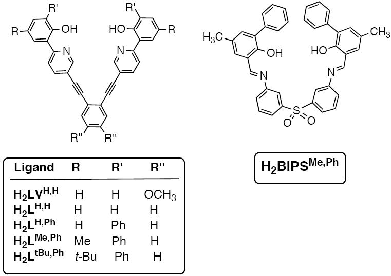
The series of 2-phenylpyridyl (left) and 2-phenoxyimino (right) dinucleating ligands synthesized.
Several routes were explored to obtain H2LR,R’. The synthetic schemes (Schemes S1-S4) and experimental details for H2LVH,H, H2LH,H, H2LH,Ph, and H2LtBu,Ph are provided in the Supporting Information. The most efficient synthetic strategy is illustrated for the preparation of H2LMe,Ph in Scheme 1. As described previously,42 protection of commercially available 2-bromo-4-methylphenol with tetrahydro-2H-pyran, followed by a Suzuki cross-coupling reaction with phenylboronic acid, gave 4 as a colorless oil. Deprotection with aqueous HCl followed by bromination with Br2 afforded 5 in 96% yield. The 3-bromo-5-methylbiphenyl-2-ol was subjected to a second protection procedure with benzyl bromide and isolated, after purification, as a white solid in 72% yield. Negishi coupling of 6 with 2,5-dibromopyridine gave 7 as a white solid in 64% yield. A Sonogashira procedure was employed to couple 7 and 1,2-diethynylbenzene. 1,2-Diethynylbenzene is susceptible to decomposition upon storage, so it was generated in situ from 1,2-bis((trimethylsilyl)ethynyl)benzene43 and tetrabutylammonium fluoride before use in the cross-coupling reaction. This procedure afforded the benzyl-protected ligand Benz2LMe,Ph in a moderate (56%) yield after purification. Finally, the desired H2LMe,Ph compound was obtained by treatment of Benz2LMe,Ph with boron tribromide in CH2Cl2 and crystallization from CH2Cl2/MeOH. The H2LMe,Ph ligand was isolated as a yellow solid in 78% yield.
Scheme 1.
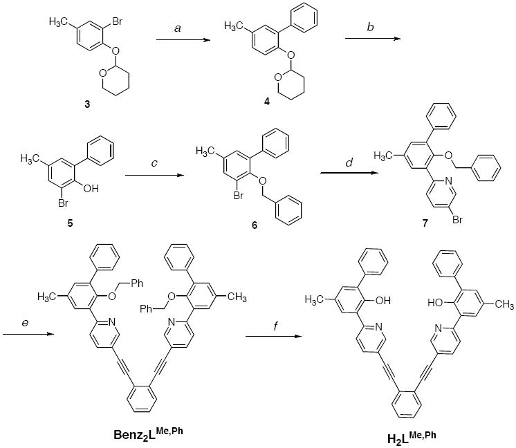
a) Phenylboronic acid, [Pd(PPh3)4], Na2CO3, THF/H2O; b) i. HCl (aq), ii. Br2, CH2Cl2; c) benzyl bromide, K2CO3, CH3CN; d) i. nBuLi, THF, -78°C, ii. ZnCl2, iii. 2,5-dibromopyridine, [Pd(PPh3)4]; e) i. 1,2-bis(trimethylsilylacetylene)benzene, NBu4F, THF, ii) [Pd(PPh3)4], NEt3; f) BBr3, CH2Cl2.
The sulfone bridged compound H2BIPSMe,Ph was synthesized according to Scheme 2. Benzylation of 2,6-dibromo-4-methylphenol with benzyl bromide provided 8 as a colorless crystalline solid. To introduce an aldehyde functionality, 8 was treated with n-butyllithium and quenched with dimethylformamide to give 9 in 65% yield. This precursor was coupled to phenylboronic acid to provide 10 in 76% yield. Cleavage of the benzyl protecting group by boron tribromide in CH2Cl2 cleanly gave 11 as a yellow oil in 76% yield. The final product was obtained by an acid-catalyzed condensation reaction between 11 and the commercially available 3,3’-diaminodiphenyl sulfone in MeOH. The desired bright orange solid, H2BIPMe,Ph, readily precipitated from the reaction mixture and was isolated in a moderate 48% yield.
Scheme 2.
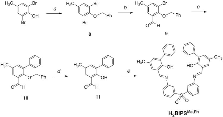
a) Benzyl bromide, K2CO3, CH3CN; b) i. nBuLi, toluene, -78°C, ii. DMF; c) phenylboronic acid, [Pd(PPh3)4], Na2CO3 THF/H2O; d) BBr3, CH2Cl2; e) 3,3’-bis(aminophenyl)sulfone, TFA, MeOH.
For the synthesis of both H2LMe,Ph and H2BIPMe,Ph, gram quantities of the final ligand were obtained. It is important to note that these multi-step routes facilitate modification of ligand substituents in a systematic manner without significant changes to the overall synthetic strategy.
UV-Vis Spectrophotometric Studies
With the compounds H2LR,R’ and H2BIPSMe,Ph in hand, we were interested to explore their iron(II) coordination chemistry. Since our goal was to construct discrete dinuclear complexes with two external carboxylates (Chart 1), we added iron(II) in a 2:1 metal-to-ligand stoichiometry. For systems that display strong optical features, a convenient way to examine metal-ligand interactions is to conduct UV-vis spectrophotometric titrations.44-46 By following spectral changes of the LR,R’ or BIPSMe,Ph (where LR,R’ and BIPSMe,Ph are the deprotonated forms of H2LR,R’ and H2BIPSMe,Ph, respectively) absorbance bands, it should be possible to assess whether they can serve as discrete dinucleating hosts.
Such titration experiments were first performed with the parent H2LH,H compound (Figure 1A). Upon deprotonation of H2LH,H with 2.0 equiv of sodium hexamethyldisilazide (NaHMDS) in THF, LH,H displayed an intense absorption at 415 nm (Figure 1A, dotted trace). When the LH,H solution was treated with various aliquots of Fe(OSO2CF3)2, two successive isosbestic points were observed, at 392 and 365 nm. These data suggest an A→B→C sequence of reactions, which would be consistent with the binding of an iron atom at one site followed by coordination of a second iron at the second metal-binding site. A plot of the absorbance change at 350 nm versus equiv of Fe(II) added (relative to LH,H) is given in Figure 2A. A gradual increase in the optical feature at 350 nm upon successive additions of iron indicates that LH,H is capable of coordinating at least two iron atoms. Saturation behavior was not observed when ≥ 2.0 equiv of Fe(II) were added.
Figure 1.
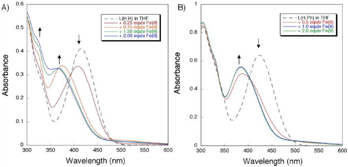
Electronic absorption spectra from the addition of Fe(OSO2CF3)2 to a THF solution containing LH,H (A, left) or LH,Ph (B, right). The dotted traces represent the spectra of the deprotonated apo-ligands, whereas the solid lines are spectra acquired after addition of various equiv of Fe(II).
Figure 2.
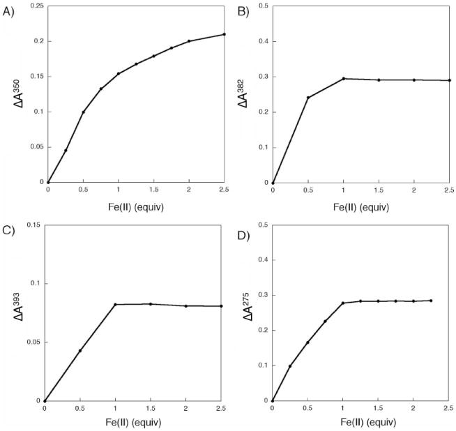
Plots of the absorbance change at a single wavelength (nm) from reaction of Fe(OSO2CF3)2 with a THF solution containing LH,H (A), LH,Ph (B), LtBu,Ph (C), and BIPSMe,Ph (D). The wavelengths were chosen to show the maximum change between successive Fe(II) titrations.
For comparison to LH,H, the optical response of the ortho substituted derivative LH,Ph to Fe(II) was examined. Reaction of H2LH,Ph with NaHMDS in THF gave LH,Ph, as indicated by the formation of a prominent absorption band at 424 nm (Figure 1B). When aliquots of Fe(II) were added to LH,Ph, a hypsochromic shift of the feature at 424 nm to 382 nm was observed. The optical spectra were unchanged after ≥ 1.0 equiv of Fe(II) were introduced (relative to LH,Ph) (Figure 2B). This result suggests that, in the presence of Fe(II), LH,Ph forms a complex having a 1:1 metal-to-ligand stoichiometry. To test the stability of this new species, various amounts of sodium triphenylacetate were added to the reaction mixture and the reaction was followed by UV-vis spectroscopy (Figure S1A). Surprisingly, the absorbance spectrum from 300-600 nm did not change after the addition of 20.0 equiv of the carboxylate (relative to LH,Ph). If coordination of triphenylacetate to iron resulted in significant geometric rearrangement, such a change should be reflected in the optical spectrum. Since no such changes were observed, we conclude that the 1:1 Fe(II)-to-LH,Ph species is too stable to be disrupted by triphenylacetate. When the reaction order was reversed, adding Fe(II) to a THF solution containing 1.0 equiv of LH,Ph and 20.0 equiv of triphenylacetate, a band at 382 nm also grew in (Figure S1B). Once again, formation of the 1:1 Fe(II) to LH,Ph species is preferred. We assign this optical spectrum to the bis-ligand diiron complex, [Fe2(LH,Ph)2] (vide infra).
To investigate the effect of bulkier ligand substituents on the iron binding of LR,R’, titration studies were also carried out with LtBu,Ph. We postulated that, by appending tert-butyl groups to the para position of the phenol ring, the increased steric demand at the ligand periphery would prevent any possible ligand-ligand interactions in the presence of Fe(II). When treated with NaHMDS in THF, H2LtBu,Ph was converted to LtBu,Ph. This free ligand displays a characteristic absorption at 437 nm (Figure S2). Upon addition of Fe(OSO2CF3)2 to a solution of LtBu,Ph, the band at 437 nm decreases, concomitant with an increased absorption at 393 nm. Just as for LH,Ph, the absorbance profile is unchanged after addition of 1.0 equiv of Fe(II) (Figure 2C). A 1:1 metal-to-ligand stoichiometry would also be consistent with the formulation [Fe2(LtBu,Ph)2].
The similar results obtained for LH,Ph and LtBu,Ph led us to hypothesize that, although LtBu,Ph is more sterically encumbering, free rotation about the ethynyl arms allows the LR,R’ ligands to “open up” and adopt a structure containing a second, interdigitated ligand. To explore whether we could maintain the “V-shaped” architecture of the LR,R’ ligand designs but restrict the rotational freedom, H2BIPSMe,Ph (Chart 2) was synthesized. Although the bis(iminophenyl)sulfone unit is not completely rigid, it is a promising alternative linker to 1,2-diethynylbenzene because it provides an ideal N⋯N distance for a dinucleating framework. Deprotonation of H2BIPSMe,Ph with NaHMDS in THF gave BIPSMe,Ph, which has a strong absorbance at 428 nm (Figure S3). When various equiv of Fe(II) were added to BIPSMe,Ph the band at 428 nm decreased, suggesting an interaction of the ligand and Fe(II). By evaluating the absorbance change at 275 nm, it is clear that a saturation point is reached after addition of 1.0 equiv of Fe(II) (Figure 2D). Thus, this study also indicates that with BIPSMe,Ph a 1:1 metal-to-ligand complex is formed preferentially in solution.
Isolation and Characterization of Iron Complexes
Since the parent LH,H compound appeared to accommodate a 2:1 metal-to-ligand ratio, we wondered whether it could be used to construct a discrete diiron complex in the presence of Fe(II) and carboxylates (Chart 1). To test this proposal, several preparative-scale reactions were performed. When H2LH,H (1.0 equiv) and triphenylacetic acid (2.0 equiv) were combined with Fe(Mes)4 (where Mes = 2,4,6-trimethylphenyl, 1.0 equiv) in THF, a dark red solid precipitated from the reaction mixture (Scheme 3A). This material was insoluble in both polar and non-polar organic solvents. When the reaction was repeated using either benzoate or acetate, instead of triphenylacetate, similar results were obtained. Since phenolate groups are well known to bridge multiple metal ions,47-49 it is possible that reaction of the underivatized LH,H ligand with Fe(II) led to the formation of polymetallic structures.
Scheme 3.
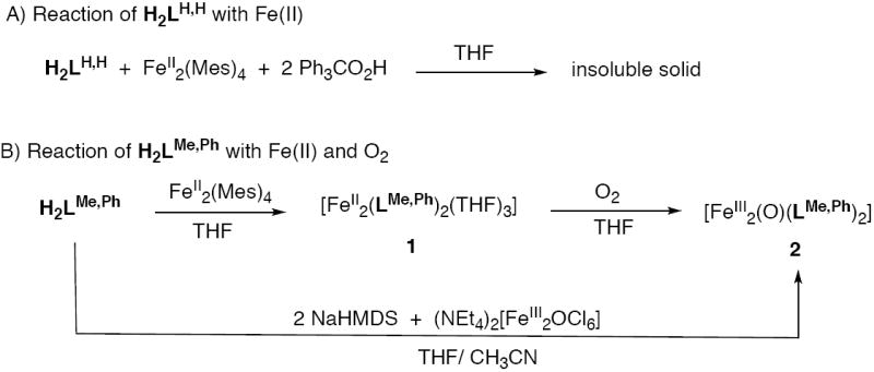
Reaction of H2LH,H with Fe(II) (A, top) and H2LMe,Ph with Fe(II) and O2 (B, bottom). Mes = 2,4,6-trimethylbenzene, NaHMDS = sodium hexamethyldisilazide.
The titration experiments with LR,R’ and BIPSMe,Ph demonstrated that when the ortho positions of the phenol rings were substituted a 1:1 metal-to-ligand complex was formed. To identify this species, we prepared the iron complex of H2LMe,Ph. Reaction of H2LMe,Ph (2.0 equiv) with Fe2(Mes)4 (1.0 equiv) in THF led to formation of a homogeneous dark red solution (Scheme 3B). Crystallization of the crude material from THF and pentane gave a dark red material in moderate yields (~50%). Single crystal X-ray diffraction analysis revealed the complex to have a diiron(II) structure with two bridging LMe,Ph ligands (Figure 3). Crystallographic data and refinement details are given in Table 1. Coordination of the iron centers by additional THF molecules gave the molecular formula [Fe2(LMe,Ph)2(THF)3] (1) in the solid state. The five-coordinate iron atom, Fe(1), adopts a distorted square pyramidal geometry, with two phenoxy oxygen (Fe-O = ~ 1.94 Å) and two pyridyl nitrogen (Fe-N = ~ 2.12 Å) atoms at the basal sites and a THF oxygen atom (Fe-O = 2.19 Å) at the apical position. The pseudo-octahedral iron center is coordinated by two phenoxy oxygen (Fe-O = ~ 1.97 Å), two pyridyl nitrogen (Fe-N = ~2.18 Å), and two THF oxygen (Fe-O = ~ 2.28 Å) atoms, with each set of donors trans to one another. A distance of 7.20 Å separates the two iron centers. The 1:1 Fe(II) to LR,R’ stoichiometry observed from the titration studies is reflected in the [Fe2(LMe,Ph)2(THF)3] formulation. Thus, it appears that in both the solid and solution states, 1 maintains the same molecular structure. A survey of the literature revealed that only a few Fe(II) complexes with terminal phenolate ligands have been isolated and characterized.50,51 Most iron-containing phenolate compounds are found in the Fe(III) state and/or have multiple metals bridged by the phenoxy moiety.52-54
Figure 3.
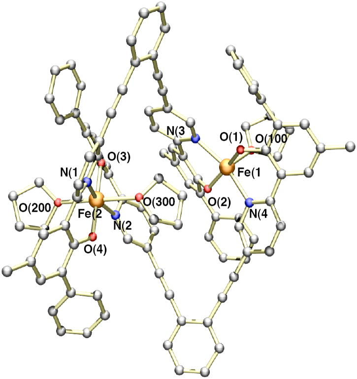
Ball and stick representation of the X-ray crystal structure of [Fe2(LMe,Ph)2(THF)3] (1) with a partial numbering scheme. Hydrogen atoms and solvent molecules have been omitted for clarity. The atoms are color coded according to the following: gray = carbon, red = oxygen, blue = nitrogen, and orange = iron. Selected bond lengths (Å) and angles (deg): Fe(1)-O(1), 1.945(3); Fe(1)-O(2), 1.936(3); Fe(1)-N(3), 2.183(4); Fe(1)-N(4), 2.193(4), Fe(1)-O(100), 2.123(3); Fe(2)-O(3), 1.967(3); Fe(2)-O(4), 1.977(3), Fe(2)-N(1), 2.180(4); Fe(2)-N(2), 2.191(4); Fe(2)-O(200), 2.203(4), Fe(2)-O(300), 2.321(3); O(1)-Fe(1)-N(4), 84.37(14); O(2)-Fe(1)-N(3), 85.98(14); O(3)-Fe(2)-N(2), 85.68(14), O(4)-Fe(2)-N(1), 85.25(14).
Table 1.
X-ray crystallographic data and refinement information for [Fe2(LMe,Ph)2(THF)3] (1).
| 1·(THF)3.5(pentane)0.5 | |
|---|---|
| Empirical formula | Fe2C120.5H118N4O10.5 |
| Formula weight | 1901.89 |
| Temperature | 110 K |
| Wavelength | 0.71073 Å |
| Crystal system, space group | Triclinic, P1̄ |
| Unit cell dimensions | a = 15.624(3) Å α = 90.39(3)° |
| b = 17.712(4) Å β = 98.51(3)° | |
| c = 18.838(4) Å γ = 106.33(3)° | |
| Volume | 4941.4(17) Å3 |
| Z, Calculated density | 2, 1.278 g/m3 |
| Theta range for data collection | 2.07 – 26.37° |
| Limiting indices | -19≤h≤ 19, -21≤k≤22, -23≤|≤22 |
| Reflections collection/ unique | 75842/ 20123 [Rint = 0.1207] |
| Completeness to theta | 99.5 % |
| Data/ restraints/ parameters | 20213/ 1390/ 1268 |
| Goodness of fit on F2 | 1.017 |
| Final R Indices | R1 = 0.0854, wR2 = 0.1860 |
The electronic absorption spectrum of 1 shows several intense features, at 235 (ε = 137,000 M-1 cm-1), 306 (ε = 94,100 M-1 cm-1), 332 (ε = 63,300 M-1 cm-1) and 395 (ε = 5,130 M-1 cm-1) nm (Figure S4). These optical signatures match the spectra observed for the Fe(II) to LR,R’ titration studies (vide supra), which suggests that the [Fe2(LR,R’)] complex was formed in solution. Due to the limited examples of Fe(II)-phenolate compounds that have been reported, it is difficult to determine whether any of these features correspond to a phenolate-to-Fe(II) charge transfer band. As a reference, phenolate-to-Fe(III) charge transfer bands are typically observed at 300-600 nm.52,55 Since the energy gap between metal d(π) and ligand p(π) orbitals for Fe(II) should be smaller than for Fe(III), it is reasonable to expect a phenolate-to-iron charge transition at lower energy for Fe(II) than Fe(III).
The 1H NMR spectrum of 1 in THF-d8 reveals the complex to be paramagnetic in solution (Figure 4A). The downfield signals at 44.45, 42.20, 38.08, and 36.30 ppm are most likely due to protons located either on the phenoxy or the pyridyl rings of LMe,Ph because they lie closest to the paramagnetic iron centers. The peak at 34.14 ppm is attributed to the methyl protons of LMe,Ph because of the relative integration value and by comparison to the spectrum of [Fe2(LH,Ph)2] in which such a feature is absent (data not shown).
Figure 4.
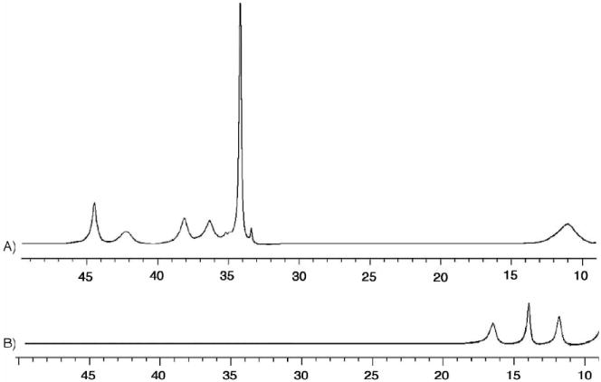
The 500 MHz 1H NMR spectra of complex 1 (A, top) and 2 (B, bottom) recorded in THF-d8. Only the paramagnetically shifted resonances (10-50 ppm) are shown.
The zero-field 57Fe Mössbauer spectrum of a polycrystalline solid sample of 1 was measured at 90 K (Figure 5A). A single quadrupole doublet appeared, with δ = 1.13 mm/s and ΔEQ = 1.88 mm/s. These parameters indicate high-spin iron(II) sites in pseudo-octahedral environments.12,56 Although there are two distinct iron atoms in the solid-state structure of complex 1, the similarities in their electronic and structural environments make the sites difficult to distinguish in the absence of an applied magnetic field. This effect most likely accounts for the slightly larger observed linewidth (ΓR,L = 0.46 mm/s).
Figure 5.
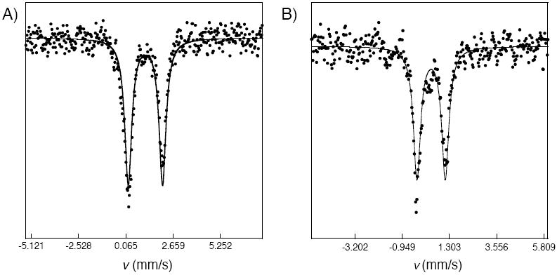
The 57Fe Mössbauer spectra of 1 (A, left) and 2 (B, right) recorded on polycrystalline samples at 90 K. Both spectra exhibit a single quadrupole doublet, with δ = 1.13 mm/s, ΔEQ = 1.88 mm/s, and ΓR,L = 0.46 mm/s for 1 and δ = 0.43 mm/s, ΔEQ = 1.35 mm/s, and ΓR,L = 0.42 mm/s for 2. Least-squares fits (solid lines), assuming Lorenztian lineshapes, are overlaid on the experimental points.
The electrochemical properties of 1 were studied by cyclic voltammetry (CV). When the CV was performed in THF, two sequential quasi-reversible redox processes were observed, at E(1/2) = -31 and −17 mV vs. ferrocene/ferrocenium (Fc/Fc+) (Figure 6A). A differential pulse voltammetry (DPV) measurement of 1 in THF revealed two oxidation peaks with maximum heights at −31 and −17 mV (Figure S8). These events are attributed to oxidation of 1 from Fe(II)Fe(II) → Fe(II)Fe(III) → Fe(III)Fe(III). When the CV of 1 was measured in DMF rather than THF, the complex exhibited one quasi-reversible redox couple at E(1/2) = -64 mV vs. Fc/Fc+ (Figure 6B). DPV measurement of 1 in DMF also confirmed that only a single redox event occurs at −64 mV (Figure S9). Presumably, this process corresponds to a two-electron oxidation of 1 from Fe(II)Fe(II) → Fe(III)Fe(III). These results suggest that electronic delocalization between the two iron centers in complex 1 is solvent dependent. From the electrochemical data, a comproportionation constant (Kcom)57 of 1 was calculated to be ~100 in THF and ~105 in DMF. According to the Robin-Day classification,58 1 behaves as a slightly charge-delocalized Class II species in THF, but becomes a completely charged-localized Class I complex in DMF. Since the UV-vis spectra of 1 in THF and DMF are identical, it is unlikely that the differences in electrochemical properties are due to different speciation in solution. It is more likely that coordination of solvent molecules to the iron centers mediate the degree of electronic communication between the two metal sites.
Figure 6.
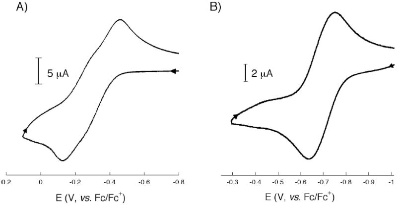
Cyclic voltammograms of a 0.2 mM solution of complex 1 containing 0.1 M tetrabutylammonium hexafluorophosphate in A) THF (left) and B) DMF (right) at a scan rate of 50 mV/s. The measurements were carried out with a Pt electrode and referenced to the Fc/Fc+ redox couple. Differential pulse voltammograms of 1 and 2 are shown in the Supporting Information (Figure S8 and S9, respectively).
Given the quasi-reversible redox behavior of 1, synthesis of the doubly oxidized [Fe2(LMe,Ph)2(THF)x]2+ complex was attempted. The E(1/2) values of 1 in THF (-31 and −17 mV vs. Fc/Fc+), indicated that [FeCp2]BF4 (Cp = cyclopentadienyl) would be a suitable oxidant. When aliquots of [FeCp2]BF4 in CH2Cl2 were added to a THF solution containing 1, clean conversion to a new species occurred, as revealed by the UV-vis spectra (Figure S5). This process could be followed by absorbance decreases at 242 and 395 nm, as well as increases at 314 and 626 nm. Since ferrocene does not absorb above 600 nm, the band at 626 nm must originate from a diiron product. Given the low intensity of this feature at 626 nm, it is possible that it arises from an Fe(III) d-d transition. Efforts to isolate and characterize the product were not successful.
Reaction of 1 with Dioxygen
The > 7 Å separation between the Fe(II) sites in complex 1 raises the question, how will it react with dioxgyen? If the metal centers were rigidly restrained at a fixed distance, exposure of 1 to O2 might lead to formation of two isolated iron-oxo or -peroxo sites within the same molecule. Alternatively, if the LMe,Ph framework were rotationally flexible, it is conceivable that O2 might bridge the two iron centers. To determine the final oxygenation product, complex 1 was dissolved in a THF solution and stirred for 5 min in the presence of O2 (Scheme 3B). The reaction product was dried in vacuo and crystallized from pentane and toluene to afford a red solid in ~80% yield. Single crystals for X-ray diffraction studies were grown from slow diffusion of pentane into a solution of the compound in THF. Because the red crystals were very small (approx. 0.20 × 0.08 × 0.05 mm3) it was difficult to acquire a high-resolution X-ray crystal structure of the compound. However, from the data it was clear that the compound contains a μ-oxodiiron(III) unit having the composition [Fe2(μ-O)(LMe,Ph)2] (2, Figure 7). The presence of an oxo bridge was also confirmed by several spectroscopic methods (vide infra). From the structure it is clear that rotation of the LMe,Ph ethynyl arms can lead to contraction of the iron-iron distance. Complex 2 was also prepared from a pre-assembled μ-oxodiiron(III) source. Upon deprotonation of H2LMe,Ph with NaHMDS in THF and addition of (NEt4)2[Fe2OCl6],59,60 a dark red solution was formed (Scheme 3B). Evaporation of the solvent and extraction of the residue into toluene gave the desired product in moderate yield (~50 %).
Figure 7.
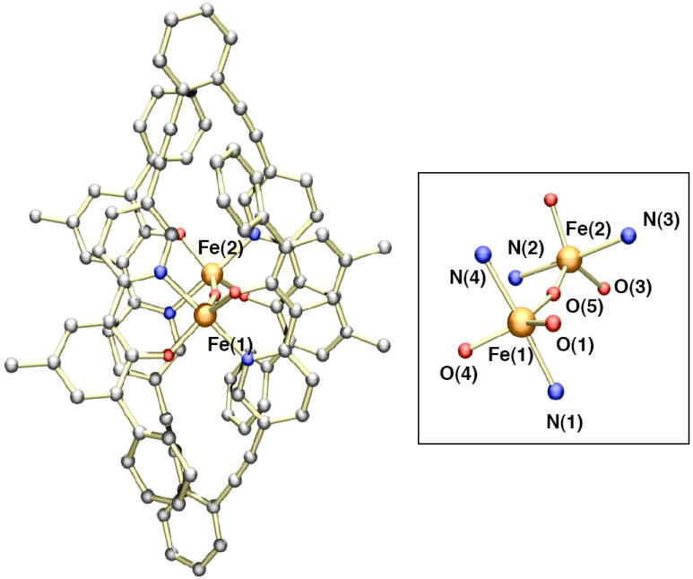
A ball and stick representation of the low-resolution X-ray crystal structure of [Fe2(μ-O)(LMe,Ph)2] (2). The coordination environment of the μ-oxodiiron(III) core is shown on the right. Due to the poor quality of the X-ray data, only the atom connectivity of the structure could be obtained. The atoms are color coded according to the following: gray = carbon, red = oxygen, blue = nitrogen, and orange = iron.
The presence of a μ-oxodiiron(III) center in 2 was further confirmed by both vibrational and 57Fe Mössbauer spectroscopy. When 2 was prepared by reaction of 1 with 18O2, instead of 16O2, its infrared spectrum revealed a single peak shifted from 833 cm-1 to 798 cm-1 (Figure 8). A survey of known μ-oxodiiron(III) complexes revealed that the asymmetric Fe–O–Fe stretch occurs between ~700-850 cm-1 and shifts to lower energy by ~30-45 cm-1 when 18O2 is substituted for 16O2.61,62 Since 2 exhibits an isotopically shifted peak within these ranges, it is clear that its diiron center also contains an oxo bridge. To probe further the oxidation state and coordination environment of 2, its 57Fe Mössbauer spectrum was measured. A Lorenztian least-squares fit of the Mössbauer data gave a single quadrupole doublet with δ = 0.43 mm/s and ΔEQ = 1.35 mm/s (Figure 5B). These parameters are common for high-spin iron centers with oxygen and nitrogen atom donors. In addition to overall charge considerations, the IR and Mössbauer data unequivocally show that formulation of 2 as a neutral μ-oxodiiron(III) [Fe2(μ-O)(LMe,Ph)2] complex is correct.
Figure 8.
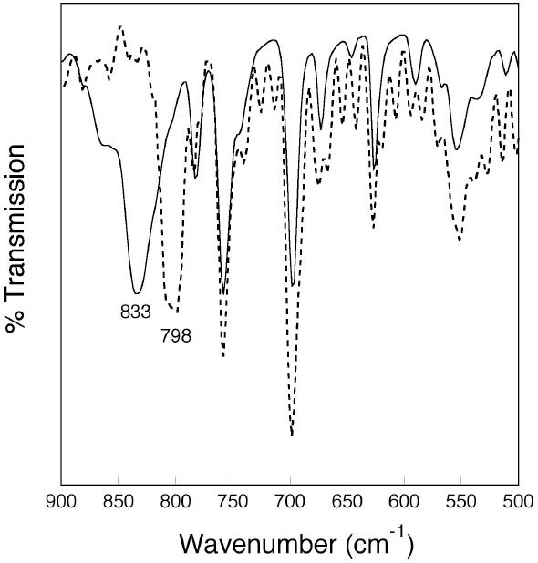
Infrared spectra (KBr) of complex 2 obtained from reaction of 16O2 (solid line) and 18O2 (dotted line) with complex 1. The labeled peaks correspond to the Fe-O-Fe asymmetric stretching mode.
The electronic absorption spectrum of complex 2 was recorded in THF. An intense band at 312 nm (ε = 108,000 M-1 cm-1) and a shoulder at ~390 nm (ε = 37,500 M-1 cm-1) dominate the spectrum (Figure S6). Since the band at ~310 nm also occurs in the spectrum of LMe,Ph, it is assigned as a p(π) → p(π*) ligand transition. For Fe(III)-phenolate complexes, the p(π) → d(σ*) and p(π) → d(π) absorbance maxima typically fall in the range ~300-600 nm.52,55 Since the spectrum of 2 shows an increased absorption between 350-390 nm, compared to the spectrum of 1, it is possible that this overlapping feature represents one of the phenolate-to-Fe(III) charge-transfer bands.
A bathochromic shift of the phenolate-to-iron LMCT band is reflected in smaller NMR contact shifts of the phenolate protons due to less mixing between the metal d and ligand orbitals.55 The 1H NMR spectrum of 2 (Figure 4B) contains only three signals outside the diamagnetic region, at 16.42, 13.90, and 11.75 ppm. Compared to the 1H NMR spectrum of 1, these peaks are less paramagnetically shifted. This result indicates that there is less unpaired spin density on the LMe,Ph ligand in complex 2 than in complex 1. Consequently, the phenolate-to-iron charge transfer bands should occur at a higher energy for 2 than for 1.
The electrochemical properties of 2 were investigated by cyclic voltammetry (Figure S10). When recorded in THF, an irreversible reduction wave was measured at −780 mV (vs. Fc/Fc+) and an irreversible oxidation wave appeared at +720 mV (vs. Fc/Fc+). The absence of reversible electrochemical behavior was unexpected because phenolate complexes are typically redox active due to involvement of phenolate radical species.63,64 A related μ-oxodiiron(III) complex containing salen ligands exhibits two reversible redox couples due to generation of ligand-centered monoradical and diradical complexes.65 The unique electronic properties of LMe,Ph preclude its classification as a typical redox active phenolate compound. Redox innocent ligands are desirable for constructing diiron hydroxylase protein models because they allow access to high-valent metal oxidation states rather than ligand-oxidized species.
The rapid conversion of 1 to 2 in the presence of O2 was studied by stopped-flow UV-vis spectrophotometry. A single mixing experiment was carried out at -50 °C, in which a 26 μM solution of 1 in THF was combined with a solution saturated with O2 (~ 10 mM). Spectral scanning between 300-750 nm revealed that the oxygenation reaction was complete in less than 10 s (Figure S7). The reaction kinetics were well fit to a single exponential function with a pseudo-first order rate constant of ~ 0.7 s-1. Even on the stopped-flow timescale, no intermediates were observed for conversion of 1 to 2. Given that O2 activation and O–O bond scission must occur to give the final μ-oxodiiron(III) product, intermediate species must form along the reaction pathway. Our inability to detect and characterize any transient species prevents us from speculating about the mechanism by which 1 converts to 2. Recent work with the ToMO enzyme system has identified a diiron(III) oxygenated intermediate lacking any obvious UV-vis absorption band that is catalytically competent to hydroxylate arenes.66 When the present oxygenation procedure was performed in the presence of triphenylphosphine, gas chromatographic mass spectral analysis of the reaction product indicated the formation of triphenylphosphine oxide. The nature of the active oxidizing species and the range of substrates that can be oxidized have not yet been evaluated. It is important to note, however, that during the course of these studies there does not appear to be any LMe,Ph ligand oxidation.
Conclusions
In our continuing search for novel frameworks to model the active sites of O2-activating diiron proteins, we prepared a new family of dinucleating ligands and provided a streamlined method for easy derivatization. By taking advantage of the chromophoric properties of LR,R’ and BIPSMe,Ph, the coordination chemistry of these ligands with Fe(II) was examined by UV-vis spectrophotometry. Incorporation of sterically demanding groups in the ligand scaffold prevented undesired polymer formation. During the course of these studies, a diiron(II) [Fe2(LMe,Ph)2(THF)3] (1) complex was synthesized having a large separation (7.2 Å) between the two metal centers. Rotation about the ethynyl arms led to a substantial contraction of the diiron distance, the structural flexibility being manifest in the oxygenation product (2) obtained from reaction of 1 with O2. [18O]-Isotopic infrared labeling studies and 57Fe Mössbauer spectroscopy clearly reveal that solutions of 2 retain the μ-oxodiiron(III) core found in the solid state by X-ray crystallography. Formation of [Fe2(μ-O)(LMe,Ph)2] most likely involves binding of O2 and concerted reorientation of the LMe,Ph ligands. Preliminary studies indicate that triphenylphosphine is converted to triphenylphosphine oxide in the presence of 1 and dioxygen, but a comprehensive study of this chemistry was not undertaken. The LMe,Ph ligand is chemically stable under these conditions and does not participate in ligand-centered redox reactions, despite the presence of the phenolate group. Although the desired diiron complex containing a single dinucleating LMe,Ph ligand was not achieved, the structure provides guidance for future modification of the LR,R’ framework to preclude formation of Fe2L2 units.
Supplementary Material
Acknowledgments
This work was supported by grant GM032134 from the National Institute of General Medical Sciences. The authors thank Dr. Zachary J. Tonzetich for helpful discussions and Prof. Wee Han Ang and Dr. Daniela Buccella for assistance with X-ray crystallography.
Footnotes
Supporting information available: experimental details, synthetic schemes, spectroscopic data, electrochemical data, and crystallographic details. This information is available free of charge via the Internet at http://pubs.acs.org.
References
- 1.Feig AL, Lippard SJ. Chem Rev. 1994;94:759–805. [Google Scholar]
- 2.Wallar BJ, Lipscomb JD. Chem Rev. 1996;96:2625–2658. doi: 10.1021/cr9500489. [DOI] [PubMed] [Google Scholar]
- 3.Du Bois J, Mizoguchi TJ, Lippard SJ. Coord Chem Rev. 2000;200-202:443–485. [Google Scholar]
- 4.Merkx M, Kopp DA, Sazinsky MH, Blazyk JL, Müller J, Lippard SJ. Angew Chem Int Ed Engl. 2001;40:2782–2807. doi: 10.1002/1521-3773(20010803)40:15<2782::AID-ANIE2782>3.0.CO;2-P. [DOI] [PubMed] [Google Scholar]
- 5.Leahy JG, Batchelor PJ, Morcomb SM. FEMS Microbiol Rev. 2003;27:449–479. doi: 10.1016/S0168-6445(03)00023-8. [DOI] [PubMed] [Google Scholar]
- 6.Sazinsky MH, Lippard SJ. Acc Chem Res. 2006;39:558–566. doi: 10.1021/ar030204v. [DOI] [PubMed] [Google Scholar]
- 7.Cafaro V, Izzo V, Scognamiglio R, Notomista E, Capasso P, Casbarra A, Pucci P, Di Donato A. Appl Environ Microbiol. 2004;70:2211–2219. doi: 10.1128/AEM.70.4.2211-2219.2004. [DOI] [PMC free article] [PubMed] [Google Scholar]
- 8.Cafaro V, Scognamiglio R, Viggiani A, Izzo V, Passaro I, Notomista E, Dal Piaz F, Amoresano A, Casbarra A, Pucci P, Di Donato A. Eur J Biochem. 2002;269:5689–5699. doi: 10.1046/j.1432-1033.2002.03281.x. [DOI] [PubMed] [Google Scholar]
- 9.Que L., Jr J Chem Soc Dalton Trans. 1997:3933–3940. [Google Scholar]
- 10.Fontecave M, Ménage S, Duboc-Toia C. Coord Chem Rev. 1998;178(180):1555–1572. [Google Scholar]
- 11.Costas M, Chen K, Que L., Jr Coord Chem Rev. 2000;200(202):517–544. [Google Scholar]
- 12.Tshuva EY, Lippard SJ. Chem Rev. 2004;104:987–1012. doi: 10.1021/cr020622y. [DOI] [PubMed] [Google Scholar]
- 13.Que L, Jr, Tolman WB. Nature. 2008;455:333–340. doi: 10.1038/nature07371. [DOI] [PubMed] [Google Scholar]
- 14.Rosenzweig AC, Frederick CA, Lippard SJ, Nordlund P. Nature. 1993;366:537–543. doi: 10.1038/366537a0. [DOI] [PubMed] [Google Scholar]
- 15.Rosenzweig AC, Lippard SJ. Acc Chem Res. 1994;27:229–236. [Google Scholar]
- 16.Sazinsky MH, Dunten PW, McCormick MS, DiDonato A, Lippard SJ. Biochemistry. 2006;45:15392–15404. doi: 10.1021/bi0618969. [DOI] [PMC free article] [PubMed] [Google Scholar]
- 17.Kuzelka J, Farrell JR, Lippard SJ. Inorg Chem. 2003;42:8652–8662. doi: 10.1021/ic034928e. [DOI] [PubMed] [Google Scholar]
- 18.Kodanko JJ, Morys AJ, Lippard SJ. Org Lett. 2005;7:4585–4588. doi: 10.1021/ol051700h. [DOI] [PMC free article] [PubMed] [Google Scholar]
- 19.Kodanko JJ, Xu D, Song D, Lippard SJ. J Am Chem Soc. 2005;127:16004–16005. doi: 10.1021/ja054943d. [DOI] [PMC free article] [PubMed] [Google Scholar]
- 20.Vetting MW, D’Argenio DA, Ornston LN, Ohlendorf DH. Biochemistry. 2000;39:7943–7955. doi: 10.1021/bi000151e. [DOI] [PubMed] [Google Scholar]
- 21.Brown CK, Vetting MW, Earhart CA, Ohlendorf DH. Annu Rev Microbiol. 2004;58:555–585. doi: 10.1146/annurev.micro.57.030502.090927. [DOI] [PubMed] [Google Scholar]
- 22.Guddat LW, McAlpine AS, Hume D, Hamilton S, de Jersey J, Martin JL. Structure. 1999;7:757–767. doi: 10.1016/s0969-2126(99)80100-2. [DOI] [PubMed] [Google Scholar]
- 23.Klose A, Solari E, Floriani C, Chiesi-Villa A, Rizzoli C, Re N. J Am Chem Soc. 1994;116:9123–9135. [Google Scholar]
- 24.Sheldrick GM. Acta Crystallogr Sect A. 2008;A64:112–122. doi: 10.1107/S0108767307043930. [DOI] [PubMed] [Google Scholar]
- 25.Sheldrick GM. SADABS: Area-Detector Absorption Corrrection. University of Göttingen; Göttingen, Germany: 2001. [Google Scholar]
- 26.Sheldrick GM. SHELXTL97: Program for Refinement of Crystal Structures. University of Göttingen; Göttingen, Germany: 1997. [Google Scholar]
- 27.Battino R, editor. Oxygen and Ozone. Vol. 7. Pergamon Press; Oxford, U.K.: 1981. [Google Scholar]
- 28.Cotton SA. Coord Chem Rev. 1972;8:185–223. [Google Scholar]
- 29.Lippard SJ. Nature. 2002;416:587. doi: 10.1038/416587a. [DOI] [PubMed] [Google Scholar]
- 30.Armstrong WH, Roth ME, Lippard SJ. J Am Chem Soc. 1987;109:6318–6326. [Google Scholar]
- 31.Lippard SJ. Angew Chem Int Ed Engl. 1988;27:344–361. [Google Scholar]
- 32.Shweky I, Pence LE, Papaefthymiou GC, Sessoli R, Yun JW, Bino A, Lippard SJ. J Am Chem Soc. 1997;119:1037–1042. [Google Scholar]
- 33.Mandal SK, Jr, Young VG, Que L., Jr Inorg Chem. 2000;39:1831–1833. doi: 10.1021/ic9912676. [DOI] [PubMed] [Google Scholar]
- 34.Hagen KS, Naik SG, Huynh BH, Masello A, Christou G. J Am Chem Soc. 2009;131:7516–7517. doi: 10.1021/ja901093b. [DOI] [PubMed] [Google Scholar]
- 35.Hagadorn JR, Que L, Jr, Tolman WB. J Am Chem Soc. 1998;120:13531–13532. doi: 10.1021/ja983333t. [DOI] [PubMed] [Google Scholar]
- 36.Lee D, Lippard SJ. Inorg Chim Acta. 2002;341:1–11. [Google Scholar]
- 37.Rosenzweig AC, Nordlund P, Takahara PM, Frederick CA, Lippard SJ. Chemistry & Biology. 1995;2:409–418. [PubMed] [Google Scholar]
- 38.Dunietz BD, Beachy MD, Cao Y, Whittington DA, Lippard SJ, Friesner RA. J Am Chem Soc. 2000;122:2828–2839. [Google Scholar]
- 39.Rinaldo D, Philipp DM, Lippard SJ, Friesner RA. J Am Chem Soc. 2007;129:3135–3147. doi: 10.1021/ja0654074. [DOI] [PMC free article] [PubMed] [Google Scholar]
- 40.Shu L, Nesheim JC, Kauffmann K, Münck E, Lipscomb JD, Que L., Jr Science. 1997;275:515–518. doi: 10.1126/science.275.5299.515. [DOI] [PubMed] [Google Scholar]
- 41.Guidote AM, Jr, Ando K-i, Terada K, Kurusu Y, Nagao H, Masuyama Y. Inorg Chim Acta. 2001;324:203–211. [Google Scholar]
- 42.Edson JB, Wang Z, Kramer EJ, Coates GW. J Am Chem Soc. 2008;130:4968–4977. doi: 10.1021/ja077772g. [DOI] [PubMed] [Google Scholar]
- 43.Boydston AJ, Haley MM, Williams RV, Armantrout JR. J Org Chem. 2002;67:8812–8819. doi: 10.1021/jo020463i. [DOI] [PubMed] [Google Scholar]
- 44.Wang B, Wasielewski MR. J Am Chem Soc. 1997;119:12–21. [Google Scholar]
- 45.Kim I-B, Dunkhorst A, Gilbert J, Bunz UHF. Macromolecules. 2005;38:4560–4562. [Google Scholar]
- 46.Fan L-J, Jones WE., Jr J Am Chem Soc. 2006;128:6784–6785. doi: 10.1021/ja0612697. [DOI] [PMC free article] [PubMed] [Google Scholar]
- 47.Murch BP, Boyle PD, Que L., Jr J Am Chem Soc. 1985;107:6728–6729. [Google Scholar]
- 48.Glaser T, Lügger T, Hoffmann R-D. Eur J Inorg Chem. 2004:2356–2362. [Google Scholar]
- 49.Boudalis AK, Aston RE, Smith SJ, Mirams RE, Riley MJ, Schenk G, Blackman AG, Hanton LR, Gahan LR. J Chem Soc Dalton Trans. 2007:5132–5139. doi: 10.1039/b709293h. [DOI] [PubMed] [Google Scholar]
- 50.Wallasch M, Wolmershäuser G, Sitzmann H. Angew Chem Int Ed Engl. 2005;44:2597–2599. doi: 10.1002/anie.200462153. [DOI] [PubMed] [Google Scholar]
- 51.Bao X, Wang F-W, Wei Y-J. Acta Crystallogr Sect E. 2006;E62:m1298–m1300. [Google Scholar]
- 52.Koch SA, Millar M. J Am Chem Soc. 1982;104:5255–5257. [Google Scholar]
- 53.Snyder BS, Patterson GS, Abrahamson AJ, Holm RH. J Am Chem Soc. 1989;111:5214–5223. [Google Scholar]
- 54.Stassinopoulos A, Schulte G, Papaefthymiou GC, Caradonna JP. J Am Chem Soc. 1991;113:8686–8697. [Google Scholar]
- 55.Pyrz JW, Roe AL, Stern LJ, Que L., Jr J Am Chem Soc. 1985;107:614–620. [Google Scholar]
- 56.Yoon S, Lippard SJ. J Am Chem Soc. 2005;127:8386–8397. doi: 10.1021/ja0512531. [DOI] [PubMed] [Google Scholar]
- 57.Zanello P. Inorganic Electrochemistry. The Royal Society of Chemistry; Cambridge: 2003. [Google Scholar]
- 58.Robin MB, Day P. Adv Inorg Chem Radiochem. 1967;10:247–422. [Google Scholar]
- 59.Armstrong WH, Lippard SJ. Inorg Chem. 1985;24:981–982. [Google Scholar]
- 60.Dunbar KR, Longridge JJ, Rawson JM, Sun J-S, Hagen KS, Do B. Inorg Synth. 2002;33:103–107. [Google Scholar]
- 61.Sanders-Loehr J, Wheeler WD, Shiemke AK, Averill BA, Loehr TM. J Am Chem Soc. 1989;111:8084–8093. [Google Scholar]
- 62.Kurtz DM., Jr Chem Rev. 1990;90:585–606. [Google Scholar]
- 63.Adam B, Bill E, Bothe E, Goerdt B, Haselhorst G, Hildenbrand K, Sokolowski A, Steenken S, Weyhermüller T, Wieghardt K. Chem-Eur J. 1997;3:308–319. doi: 10.1002/chem.19970030221. [DOI] [PubMed] [Google Scholar]
- 64.Roy N, Sproules S, Weyhermüller T, Wieghardt K. Inorg Chem. 2009;48:3783–3791. doi: 10.1021/ic8023716. [DOI] [PubMed] [Google Scholar]
- 65.Strautmann JBH, Freiherr von Richthofen C-G, George SD, Bothe E, Bill E, Glaser T. Chem Commun. 2009:2637–2639. doi: 10.1039/b903500a. [DOI] [PubMed] [Google Scholar]
- 66.Murray LJ, Naik SG, Ortillo DO, García-Serres R, Lee JK, Huynh BH, Lippard SJ. J Am Chem Soc. 2007;129:14500–14510. doi: 10.1021/ja076121h. [DOI] [PMC free article] [PubMed] [Google Scholar]
Associated Data
This section collects any data citations, data availability statements, or supplementary materials included in this article.


