Abstract
We introduce an in vivo imaging flow cytometer, which provides fluorescence images simultaneously with quantitative information on the cell population of interest in a live animal. As fluorescent cells pass through the slit of light focused across a blood vessel, the excited fluorescence is confocally detected. This cell signal triggers a strobe beam and a high sensitivity CCD camera that captures a snapshot image of the cell as it moves down-stream from the slit. We demonstrate that the majority of signal peaks detected in the in vivo flow cytometer arise form individual cells. The instrument’s capability to image circulating T cells and measure their speed in the blood vessel in real time in vivo is demonstrated. The cell signal irradiance variation, clustering percentage, and potential applications in biology and medicine are discussed.
1. Introduction
An in vivo flow cytometer [I] is a simple confocal microscope that can provide real-time detection and quantitative information of fluorescently labeled cells in circulation in a live animal model. As the labeled cells pass through the beam of a cw laser (termed as “counting laser”) that is focused to a slit across a blood vessel, fluorescence is excited and then detected by a photo multiplier tube (PMT) located behind a confocal slit aperture. This confocal detection of cells in circulation makes observing a cell population of interest possible, without the need to extract blood samples. This advantage allows the same cell population to be tracked continuously and over long periods of time in order to examine its dynamic changes in the circulation. The in vivo flow cytometer has been used to measure the circulation lifetime of different tumor cells as well as to monitor apoptotic cells in circulation [2–4]. However, the ability of the in vivo flow cytometer to detect single cells in circulation has so far not been demonstrated directly. It is conceivable that the instrument sensitivity is insufficient to detect single cells and only cell clusters are detected. To verify that signal peaks in our in vivo flow cytometry traces truly correspond to single cells, we have developed an in vivo imaging flow cytometer that captures an image of the fluorescently labeled cell as it moves downstream from the counting laser slit, using the counting signal as a trigger for the strobe light and the CCD to produce a “stop action” image of the moving cell. With this new system, we are able to show that approximately 98% of the peaks in the original in vivo flow cytometer are signals from single cells, and only ~2% are clusters. We further discuss the potential biomedical applications of the combined counting and imaging flow cytometer.
2. Materials and methods
2.1 Setup
The in vivo imaging flow cytometer is based on the original in vivo flow cytometer that is explained in more detail by Novak et al. [1]. The schematic of the experimental setup is shown in Fig. 1. A test animal is anesthetized and placed on the XYZ translation stage with its ear adhered to a microscope slide using 2% Methocel. To identify the blood vessel location for measurement, the mouse ear is transilluminated by a green LED and imaged onto a CCD camera with a large field of view.
Fig. 1.
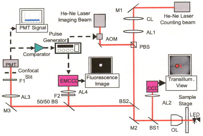
Schematic diagram of the in vivo imaging flow cytometer. M1–M3: mirrors, AL1–AL4: achromats, BS1–BS2: dichroic beam splitters, F1–F2: bandpass filters, CL : cylindrical lens, OL: microscope objective lens. Red lines indicate optical path. Dashed black arrows indicate electrical connections.
The underlying principle of the in vivo flow cytometer is confocal excitation and detection of fluorescently labeled cells in circulation. Light from a linearly polarized counting laser (cw He:Ne laser, λ = 632 nm, Melles Griot, 05-LHP-991, Carlsbad, CA) is focused to a slit by a cylindrical lens and imaged across the selected blood vessel with a microscope objective lens (40 ×, 0.6 NA). Fluorescence is excited as a labeled cell passes through the slit of the counting beam. The emitted fluorescence is collected by the microscope objective and separated from the excitation light by a dichroic beam splitter (BS2). After passing the 50/50 beam splitter, the beam is imaged on a 200 μm × 3000 μm mechanical slit, which is confocal with the excitation slit. This confocal arrangement eliminates light from out-of-focus fluorescent and scattering sources. Fluorescence is detected with a PMT (Hamamatsu, R3896, Hamamatsu City, Japan) placed directly behind the confocal slit. A bandpass filter (F1) placed in front of the confocal slit prevents most of the backscattered excitation light from entering the detector. The analog signal from the PMT is digitized and stored on a computer. Converting the existing device into an in vivo imaging flow cytometer is made possible by employing a second He:Ne “imaging laser,” with a center wavelength at 635 nm (Coherence, Radius 635-25, Santa Clara, CA) that serves as the strobe beam for a wide field microscope. The imaging laser has a power output of 30 mW and is linearly polarized. In order to produce strobe pulses of varying duration, the cw imaging laser is gated using an acousto-optic modulator (AOM, Andersen Laboratory, DLM-40-V-7, Bloomsfield, CN) that is controlled by a function generator.
The polarizing beam splitter (PBS) was employed to overlay the two lasers. The counting laser beam is transmitted through the PBS, while the imaging beam, with a polarization orthogonal to the counting beam, is deflected by the PBS; thus, the PBS acts as a beam combiner. The imaging beam, with a diameter of approximately 20 μm (1/e2), is separated by about 25 μm from the counting slit on the target surface.
The excited fluorescence is separated by a dichroic beam splitter (BS2) and further split by a 50/50 beam splitter. 50% of the beam are reflected and imaged on the Electron Multiplying CCD (EMCCD; Andor Technnology, DV 885, Belfast, UK) through a tube lens with focal length of 400 mm (AL4). A bandpass filter (F2) was placed in front of the tube lens to block unwanted light other than the fluorescence. A PC-based frame grabber captures the fluorescence image and saves it as a digital file.
2.2 Timing
The PMT “counting signal” is applied in parallel to the digitizer and to an OP-amp based comparator. When the PMT signal from a passing cell crosses a threshold value (~1V), the comparator triggers the arbitrary function generator (AFG). Upon triggering, the AFG sends a pulse to both the AOM and EMCCD with a given delay (a few tens ms) in order to capture an image of the passing cell. In order to fire the strobe pulse when the cell was in the region of the illumination spot, the pulse delay was adjusted according to the distance between the counting slit and the illumination spot.
The illumination time was matched to the estimated speed of the cells to avoid the blurring caused by movement during the exposure (dynamic blurring). The pulse duration was set to 200 μs for those blood vessels in which flow velocity ranges between about 2 mm/s and about 5 mm/s; most observed vessels fell into this category. The pulse duration was increased to 400 μs pulse for vessels with flow velocity less than about 2 mm/s. For cells with a speed of less than 5 mm/s, the 200 μs imaging pulse induces a dynamic blurring of 1 μm at most. A pulse shorter that 200 μs can be used for further reducing dynamic blurring; however, a shorter pulse also reduces the total emission of fluorescence at a given laser power.
2.3 Velocity
The cell speed was measured in two different ways: 1) Using a single strobe pulse, the velocity was calculated based on the distance the cell traveled from the counting slit and the delay of the imaging pulse. 2) Due to the fast response time of the AOM, multiple snapshots of a single cell were possible by applying a series of properly delayed imaging pluses (two or three pulses). By applying repetitive imaging pulses during the integration time of the EMCCD, one cell was imaged multiple times in one image. The speed was determined by measuring the distance the cell has traveled between two consecutive pulses.
2.4 Gain
One goal of the in vivo imaging flow cytometer is to answer the question of whether frequently observed saturated PMT signals are caused by cell clusters. In a typical counting experiment, the PMT is used with a gain of approximately 1.5 × 10⁶. The PMT gain was reduced by a factor of ten and kept constant for most experiments in order to examine the variation in PMT traces that would be saturated at the typical gain setting. This allowed us to compare the amplitude of the PMT trace with the cell brightness in the captured image. In order to compare the sensitivity of PMT versus camera, the PMT was sometimes used at the normal gain setting of 1.5 × 10⁶.
2.5 Cells, markers and animals
The cells used in our experiments were murine CD4+ T cells that were collected and purified from the harvested spleen and lymph nodes of BALB/c mice using the Dynal® Mouse CD4 Cell Negative Isolation Kit (Invitrogen Corporation, Carlsbad, CA). The isolated T cells were labeled ex vivo with 20 μM Vybrant® DiD (a lipophilic fluorescent dye that binds to the cell membrane; excitation peak at 647 nm and emission peak at 669 nm) from Molecular Probes (Invitrogen Corporation, Carlsbad, CA). The fluorescence characteristics of the labeled population were analyzed by in vitro flow cytometry prior to injection (FACSCalibur, Bcckton-Dickinson, Franklin Lakes, NJ). 1–2 × 10⁶ cells were injected into the mouse circulation through the tail vein. Circulating fluorescent cells were observed in the ear vasculature, which is representative of the whole mouse circulation, as cells injected via the tail vein rapidly circulate throughout the body. In addition, the shallow depth of the vessels as well as the contrast between the absorbing blood vessels and the relatively transparent ear tissue, allows for easy identification of appropriate size arteries. The average diameter of the observed arteries was about 20 μm. A total of five mice were examined in these experiments, starting 30 minutes after injection and lasting up to several hours. As a reference for the in vivo imaging, labeled CD4+ T cells were examined ex vivo using the above-described imaging flow cytomcter (continuous irradiation at low power setting) and a commercial fluorescence microscope (Zeiss, IM35, Göttingen, Germany).
3. Results
The fluorescence characteristics of the isolated T cell population were analyzed by conventional flow cytometry prior to injection. A typical flow cytometry plot is presented in Fig. 2. The X-axis represents forward scattering, correlated to cell size (increasing with cell diameter). The Y-axis represents the intensity of fluorescence labeling. According to the in vitro flow cytometry data, about 99% of injected cells are the size of T cells, appearing in the upper left quadrant of the fluorescence and scattering plot. About 1 % of the population are found in the upper right quadrant, indicating these are cells larger than the T cell. These cells can include monocytes and granulocytes. Lineage specific analysis (not shown) performed in vitro using CyChrome-conjugated anti-CD4 mAb (Pharmingen/Becton-Dickinson Biosciences, San Jose, CA) demonstrates that the isolated population was 94–95% CD4-positive T cells. The remaining CD4-negativc cells are most likely CD8+ T cells and B cells that have similar size as T cells. Altogether, the total percentage (5–6%) of the impurity is consistent with the manufacturer’s specification for the negative isolation process, but only about 1% of the cells are significantly larger than T cells.
Fig. 2.
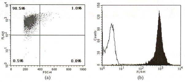
A typical result of in vitro flow cytometry of a DiD-labeled cell population. The X-axis in the scatter plot (a) represents forward scattering, which is correlated to cell size (increasing with cell diameter). The Y-axis represents the intensity of fluorescence labeling. About 99% of the labeled cells are the size of T cell, appearing in the upper left quadrant of the fluorescence and scattering plot. However, about 1% of population (upper right quadrant) is comprised of cells bigger than T cells or potential cell aggregates. The histogram (b) demonstrates that fluorescence intensity of DiD-labeled cells is well separated from unlabeled control cells.
Ex vivo fluorescence images taken with a commercial fluorescence microscope and our new imaging flow cytometer (Fig. 3) show morphologically consistent lymphocytes with an average diameter of about 5 μm. Fluorescence intensity varies among cells. Furthermore, distribution of the fluorescent marker DiD was inhomogeneous within individual cells.
Fig. 3.
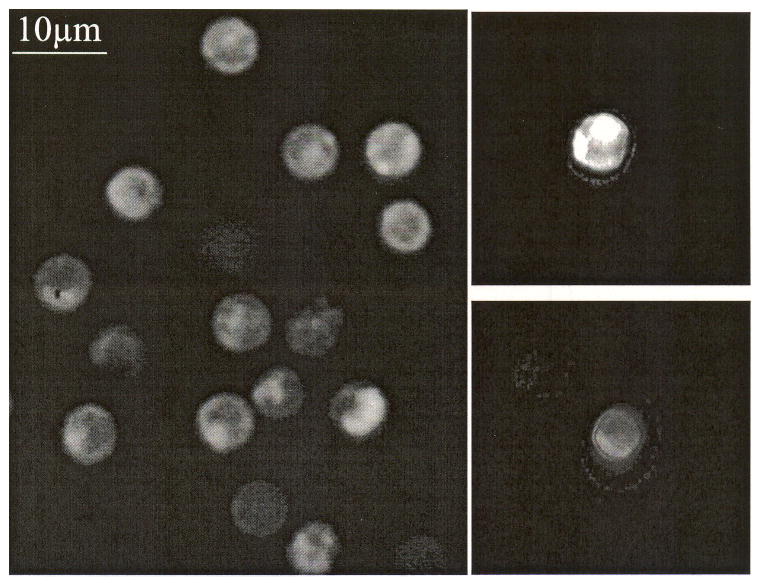
Ex vivo images of DiD-labeled T cells. (a) image taken with a commercial fluorescence microscope and (b) images taken with the imaging flow cytometer
The in vivo imaging flow cytometer allowed the identification of DiD-labeled murine T cells circulating in arteries (Fig. 4(a)). As in the ex vivo images, the brightness among cells varies and the staining of individual cells is inhomogeneous, so that highly labeled areas in a cell appear brighter than others. Most observed cells were circulating as single cells, while clustered T cells were rarely found. Altogether, 119 images were evaluated to distinguish the clustered cells from single cells (only images that are in focus are analyzed). Of these, 117 showed individual cells while two cases clearly presented clusters of T cells (Fig. 4(c)). Occasionally, two cells traveling in close proximity to each other were imaged with a single exposure of the imaging beam (Fig. 4(e)). The PMT trace for a single cell displays a bell shape counting signal (Fig. 4(b)). The second spike in this figure is the fluorescence caused by the imaging pulse. The PMT trace for the cluster presents a single counting signal with a shoulder in the rising slope (Fig. 4(d)). The trace for two cells is manifested as two distinct peaks (Fig. 4(f)). With a reduced PMT gain, peak intensities remained mostly below saturation levels; however, highly fluorescent cells occasionally produced saturated PMT intensity, as shown in the second peak of Fig. 4(f).
Fig. 4.
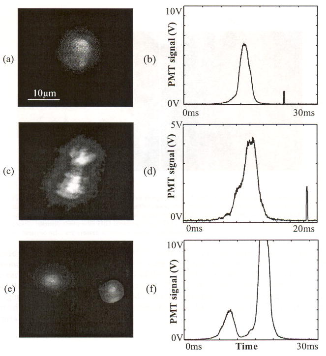
In vivo images and corresponding PMT traces of a single T cell ((a), (b)), a cluster of two T cells ((c), (d)), and two cells traveling in close proximity to each other ((e), (f)).
An ex vivo and in vivo image of a non T cell is presented in Fig. 5(a) and (b), respectively. Even though the exact cell type cannot be determined, the cell can be distinguished from a regular T cell due to its size and shape that appears to be irregular and distinctly different from the usual manifestation of T cells.
Fig. 5.
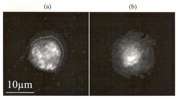
(a) Ex vivo image and (b) in vivo image of non T cell. These cells can be distinguished from a T cell due to its bigger size. Furthermore, their surface structure appears to be irregular and distinctly different from the usual appearance of T cells. However, it is not possible to clearly identify them with DiD labeling alone. They are most likely not dead cells, as apoptotic or necrotic cells are cleared from circulation within minutes [3].
Figure 6 shows in vivo images of T cells with distinct brightness, along with their corresponding PMT traces. Cell images were captured from the same vessel of the same mouse ear. The first, bell-shaped signal of the PMT trace is caused by a cell passing through the counting slit (i.e., the “counting signal”). The second spike is the fluorescence caused by the imaging pulse. Cells with higher PMT intensity produced brighter images. This trend was confirmed by plotting the total photon count from the CCD against PMT voltage for a typical set of measurements (Fig. 6(d)).
Fig. 6.
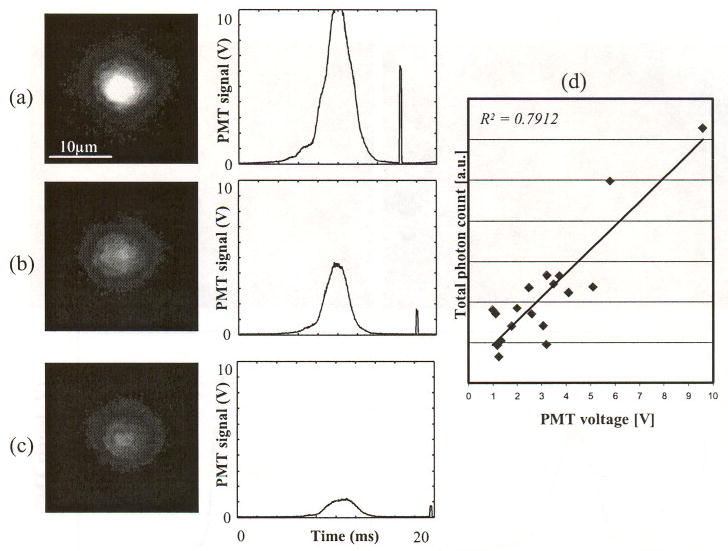
In vivo images of DiD-labeled T cells and corresponding PMT traces, (a) brightest, (b) medium brightness, (c) darkest cell, and (d) the total photon count against PMT voltage. The first bell-shaped pulse is induced by a cell passing through the slit. The second short pulse is induced by the imaging pulse. Since the gain for the PMT and the intensified CCD camera were constant for these measurements, the difference in brightness is intrinsic to the cell labeling.
In vivo images of two cells with distinct velocities and corresponding PMT traces are displayed in Fig. 7. The slit of the counting beam is illustrated in order to compare the travel distance of the two cells. The second pulse in both traces is produced by the fluorescence excited by the imaging beam. The imaging beam and EMCCD were triggered 10 ms after the counting PMT signal crosses the threshold (1 V). The cell in Fig. 7(a) traveled approximately 34 μm, while the cell in Fig. 7(b) traveled about 19 μm. Travel time was measured to be 9 ms from the counting signal peak to the center of the imaging beam signal in the trace. Assuming cells were traveling along a straight line that is perpendicular to the slit, the speed of cells can be estimated to be 3.8 mm/s and 2.1 mm/s for cells (a) and cell (b), respectively. As expected, cells with lower velocities produced temporally wider PMT spikes.
Fig. 7.
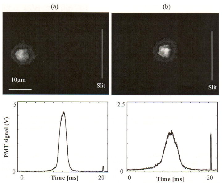
In vivo image of cells in circulation with different speed and corresponding PMT traces. The speed was estimated a straight path from the slit to the captured position, (a) a fast cell with a speed of 3.8 mm/s and (b) a slow cell with a speed of 2.1 mm/s.
An image of a single cell acquired by two consecutive imaging pulses and the corresponding PMT trace are displayed in Fig. 8. The first imaging pulse was triggered 20 ms after the cell signal and the second imaging pulse followed 20 ms later. The trajectory of the cell in the blood vessel can be estimated from the sequence of images. The speed was calculated at 0.67 mm/s, based on the travel distance and time delay between two imaging pulses.
Fig. 8.
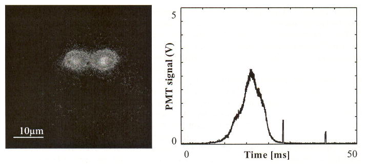
In vivo image of a cell with two consecutive imaging pulses and corresponding PMT trace. Two pulses are temporally separated by 20 ms and the image pulse duration is 400 μs. The measured traveling speed of cell is 0.67 mm/s.
4. Discussion
We have developed an in vivo imaging flow cytometer that captures images of fluorescently labeled cells in circulation after they passed a counting laser slit. After analyzing 119 images of DiD-labeled murine T cells it became apparent that the vast majority of the signal peaks detected by in vivo flow cytometry correspond to single cells, while only a small percentage (2 out of 119) are potential clusters. Furthermore, image brightness and PMT signal height correlated well as Fig. 6 shows.
Variations in the PMT peak intensity can be explained in two ways: 1) the variability of the fluorescence staining intensity and 2) the axial location of the cells. According to the conventional flow cytometry measurement (Fig. 2(a), note the vertical axis is in log scale), the difference in fluorescence intensity among most labeled cells (98%) is approximately thirty-fold. This kind of variation is normal in typical cell staining experiments. In addition, the in vivo PMT peak intensity depends on where the cells pass through the slit of the counting beam. First, the radiant exposure of the excitation light and the resultant fluorescence vary as a function of axial location of a cell due to the beam propagation. Second, the confocal rejection of emitted fluorescence varies with the axial location of a cell. This dependency of radiant exposure and confocal rejection on axial location was tested ex vivo with DiD-stained CD4+ T cells. After placing the cells (on a microscope slide) in the center of the counting slit, the fluorescence was measured using the PMT as a function of the axial location (at the focal plane and ± 12.5 μm from the focus). From measurements of ten distinct cells, the average PMT signal variation over 25 μm is 37 ± 9 %.
The current system’s maximum acquisition rate is about 100 frames per second, dictated by the readout speed of the EMCCD. This frame rate is sufficient because the typical cell count in a typical in vivo flow cytometer measurement is approximately 100 cells per minute [2–4]. With the in vivo imaging flow cytometer, the absolute speed of the cells can be measured precisely based on the travel distance (from the center of the slit to the center of the captured cell image) and the travel time (the delay between the peak of the counting spike and the image pulse), assuming that the cell travels along a straight path that is perpendicular to the counting slit. To determine if the direction deviates from this straight-line assumption, multiple exposures of the imaging beam can be employed (Fig. 8). Multiple illuminations of a single cell within one imaging frame acquired by at least two consecutive pulses can provide additional information on the direction of the flowing cell. The velocity of the cell can be accurately calculated based on the travel distance and the delay between two imaging pulses. The speed of circulating cells can be estimated alternatively from the PMT signal itself. Since less time is required for a fast cell to cross the slit of the counting beam compared to a slow cell, a fast cell produces a spike with a narrower full width half maximum (FWHM). As shown in a previous paper, cells in an artery produce narrower signals than cells in a vein [1], However, without knowledge of the exact dimensions of each cell, this measurement can provide only an approximate cell velocity.
The imaging flow cytometer also allows us to directly compare the sensitivity of the imaging system relative to the counting system. Using normal PMT gain setting that is usually used in counting experiments, imaging system was able to capture snapshot images for cells that produce saturated and high PMT peak intensity (about 35% of all PMT cell signals). For cells that produced a low to mid PMT amplitude (1–7 V), detected fluorescence was insufficient to produce images of those cells.
In summary, we have used stroboscopic fluorescence imaging to observe the same cells that are detected by the counting beam. However, the imaging system can be modified to take advantage of other contrast mechanisms such as white light imaging and photothermal imaging [5]. Advantages of the combined imaging flow cytometry include (i) both quantitative and morphologic information can be obtained simultaneously (a commercial in vitro system is available that offers such combined imaging and flow cytometry information, see Amnis.com), and (ii) in the case of rare events, the trigger signal from the counting beam allows us to capture images of rare cells of interest without having to sort through massive files of high-speed video data, most of which do not contain the rare events of interest. For example, using the combined system, we can begin to investigate whether circulating cancer cells can be distinguished from white blood cells, or activated lymphocytes from their resting counterpart, without the need to inject multiple fluorescent probes that can be problematic in vivo. Future studies will also include imaging and counting cells in an auto-perfused flow chamber [6], and in an artificial microvascular network used for tissue-engineered organs [7].
Footnotes
OCIS codes: (170.3880) Medical and biological imaging; (170.0170) Medical optics and biotechnology
Contributor Information
Ho Lee, Email: holee@knu.ac.kr, Wellman Center for Pholomedicine, Massachusetts General Hospital, Harvard Medical School, Boston, MA 02114, USA, Kyongpook National University, Daegu 702-701, South Korea.
Clemens Alt, Wellman Center for Photomedicine, Massachusetts General Hospital, Harvard Medical School, Boston, MA 02114, USA, Department of Biomedical Engineering, Tufts University, Medford, MA 02155,USA.
Costas M. Pitsillides, Wellman Center for Photomedicine, Massachusetts General Hospital, Harvard Medical School, Boston, MA 02114, USA, Department of Biomedical Engineering, Boston University, Boston, MA 02215,USA
Mehron Puoris’haag, Wellman Center for Photomedicine, Massachusetts General Hospital, Harvard Medical School, Boston, MA 02114, USA.
Charles P. Lin, Email: lin@helix.tngh.harvard.edu, Wellman Center for Photomedicine, Massachusetts General Hospital, Harvard Medical School, Boston. MA 02114, USA
References and links
- 1.Novak J, Georgakoudi I, Wei X, Prossin A, Lin CP. In vivo flow cytometer for real-time detection and quantification of circulating cells. Opt Lett. 2004;29:77–79. doi: 10.1364/ol.29.000077. [DOI] [PMC free article] [PubMed] [Google Scholar]
- 2.Georgakoudi I, Solban N, Novak J, Rice WL, Wei X, Hasan T, Lin CP. In vivo flow cytometry: a new method for enumerating circulating cancer cells. Cancer Res. 2004;64:5044–5047. doi: 10.1158/0008-5472.CAN-04-1058. [DOI] [PubMed] [Google Scholar]
- 3.Wei X, Sipkins DA, Pitsillides CM, Novak J, Georgakoudi I, Lin CP. Real-time detection of circulating apoptotic cells by in vivo flow cytometry. Mol Imaging. 2005;4:415–416. doi: 10.2310/7290.2005.05148. [DOI] [PMC free article] [PubMed] [Google Scholar]
- 4.Sipkins DA, Wei X, Wu JW, Runnels JM, Côté D, Means TK, Luster AD, Scadden DT, Lin CP. In vivo imaging of specialized bone marrow endothelial microdomains for tumour engraftment. Nature. 2005;435:969–973. doi: 10.1038/nature03703. [DOI] [PMC free article] [PubMed] [Google Scholar]
- 5.Zharov VP, Galanzha EI, Tuchin VV. In vivo photothermal flow cytometry: imaging and detection of individual cells in blood and lymph flow. J Cell Biochem. 2006;97:916–932. doi: 10.1002/jcb.20766. [DOI] [PubMed] [Google Scholar]
- 6.Hafezi-Moghadam A, Thomas KL, Cornelssen C. A novel mouse-driven ex vivo flow chamber for the study of leukocyte and platelet function. Am J Physiol Cell Physiol. 2004;286:C876–C892. doi: 10.1152/ajpcell.00500.2003. [DOI] [PubMed] [Google Scholar]
- 7.Shin M, Matsuda K, Ishii O, Terai H, Kaazempur-Mofrad M, Borenstein J, Detmar M, Vacanti JP. Endothelialized networks with a vascular geometry in microfabricated poly(dimethyl siloxane) Biomed Microdevices. 2004;6:269–278. doi: 10.1023/B:BMMD.0000048559.29932.27. [DOI] [PubMed] [Google Scholar]


