

Abstract
Purpose
Retinal microsurgery requires extremely delicate manipulation of retinal tissue where tool-to-tissue interaction forces are usually below the threshold of human perception. Creating a force sensing surgical instrument that measures the forces directly at the tool tip poses great challenges due to the interactions between the tool shaft and the sclerotomy opening.
Methods
We present the design and analysis of a force measurement device that senses distal forces interior to the sclera using 1 cm long, 160 μm diameter Fiber Bragg Grating (FBG) strain sensors embedded in a 0.5mm diameter tool shaft. Additionally, we provide an algorithm developed to cancel the influence of environmental temperature fluctuations.
Results
The force sensing prototype measures forces with a resolution of 0.25mN in 2DOF while being insensitive to temperature.
Conclusion
Sub-miliNewton resolution force sensors integrated into microsurgical instruments are feasible and have potential applications in both robotic and freehand microsurgery.
Keywords: Microsurgery, Force Sensor, Surgical Instruments, Computer-assisted surgery
INTRODUCTION
Many clinical procedures involve intervention and manipulation of extremely small, delicate tissue structures. Retinal microsurgery is an example of the requirement for micron-level maneuvers. The manipulation of vitreoretinal structures inside the eye poses enormous challenges, due to tissue delicacy, surgical inaccessibility, suboptimal visualization, and the potential for irreversible tissue damage resulting from unintentional movement.
In current practice, retinal surgery is performed under a surgical microscope. Small (20–25 gauge) surgical instruments are inserted through the sclera of the eye through operative sclerotomy sites (typically, 2–3). The main technical limitations in vitreoretinal surgery are:
inadequate spatial resolution and depth perception of microstructures to identify tissue planes,
imprecise movements during micromanipulation of tissue due to physiological tremor. Physiological tremor contributes to increases in operative time is exacerbated by fatigue, and is a significant limiting factor in microsurgery [1].
lack of force sensing since the movements required for dissection are below the surgeon’s sensory threshold. Gupta et al. reported that a majority of retinal surgery is performed without force sensation of the interactions between retinal tissue and the surgical tool [2].
These factors collectively not only make vitreoretinal surgery the most technically demanding ophthalmologic surgery, but also apply similarly to other microsurgical disciplines such as other microsurgical disciplines such as otolaryngology, vascular surgery as well as neurosurgery. At Johns Hopkins University, we have had a long-standing research program intended to address these limitations. The present program utilizes the steady-hand “Eye Robot” [3, 4] and various “sensory substitution” schemes to provide the surgeon with feedback on tool-to-tissue forces that would otherwise be imperceptible [5].
There have been several investigations of force sensing for microsurgery over the years. For example, Zhou et al. [6] developed a force sensing scheme relying on measuring the deflection of an optical beam. Kim et al. [7] developed multi-axis MEMS force sensors in an approximately 3 ×5 × 0.5 mm form factor. Menciassi et al. [8] developed a 15.5 mm micro-gripper with integrated strain gauge sensors. Early work by Gupta et al. [2] included use of a 1 DOF pick-like probe to measure forces in retinal surgery and to explore the feasibility of a simple auditory “sensory substitution” scheme to assist the surgeon in controlling these forces. They determined that 75% of these forces were less than 7.5 mN in magnitude and that only 19% of force events of this magnitude are felt by the surgeon. Subsequently, Berkelman et al. developed a 3 DOF force sensor [9, 10] for use in ENT and eye applications with the JHU “Steady Hand” microsurgery system. Jagtap & Riviere [11] incorporated this sensor into a hand-held instrument and used it to measure forces in retinal tasks both on cadaveric pig retinas and in vivo rabbit eyes. Experience with this instrument shows that in vivo measurements are indeed feasible, but that discrimination between forces applied at the tool tip and forces from contact with the sclera may be a challenge if the force sensing is done proximal to the sclerotomy point. The difficulty is not so much friction between the tool shaft and sclerotomy opening as it is lateral forces exerted on the tool shaft during tool manipulation.
These prior approaches pose a number of limitations to retinal microsurgery application. With the exception of [2], which used a strain gauge along the tool shaft, the sensor “packages” are too large to be incorporated easily into the portion of the microsurgical tool that is inside the eye. Placing a multi-axis force sensor in the tool handle, as was done in [9, 10] necessarily introduces significant sclera-to-tool force disturbances that can completely swamp the tool-to-tissue force measurements. Fabricating custom micro-MEMS sensors into the actual tool tip (e.g., into a 0.5 mm cutter blade or tweezers tip) is conceptually possible, but poses numerous fabrication, assembly, and interfacing problems.
These considerations led us to explore approaches in which sensors could be mounted along the portion of the tool shaft inside the eye. We looked at several sensing technologies, including conventional strain gauges, but settled on Fiber Bragg Grating (FBG) strain sensors. Optical fiber sensors are small (75–200μm diameter), extremely precise, mechanically stable, immune to electrical noise, sterilizable, relatively inexpensive, and can be built into a ~1mm diameter tool. In addition, expertise gained at integrating FBGs into our tools could be readily transferred to other fiber-optic sensors and devices for microsurgery, as well as into other robotic and sensing applications in our laboratory.
In subsequent sections, we will describe the functional requirements and conceptual design for our force sensing tools. After presenting preliminary validation experiments with a 1 DOF prototype, we will describe the design of a temperature-insensitive 2 DOF tool family, with calibration test results showing its performance. Finally, we will present initial results using a 2 DOF hook tool on a membrane peeling phantom.
Material and Methods
Tool Functional Requirements and Conceptual Design
The design of the force sensing surgical instrument has to meet both form factor constraints and measurement resolution requirements. The geometry of the surgical environment inside of the eye dictates the sensing element location, which should be close to the distal end of the tool. The sensor should not compromise the overall size of the instrument, and the device should have the capability of measuring forces at the tip with sub-mN resolution. Detailed functional specifications are listed in Table 1.
TABLE 1.
Design specifications for the force sensing tool
| Tool shaft diameter | < 1 millimeter |
| Tool shaft length | > 30 millimeter |
| Force Resolution at tip | ~ 0.25 millinewton |
| Sampling Rate | > 100 Hz |
The conceptual design of the force sensing tool is shown in Figure 1. As discussed in the introduction, our design approach relies on FBG strain sensors. FBG technology has been used in a number of important application areas ranging from structural monitoring to chemical sensing [12]. Bragg sensors consist of a grating formed inside of a photosensitive optical fiber by exposure to an intense optical interference pattern, which effectively creates a wavelength specific dielectric mirror inside of the fiber core. This characteristic Bragg wavelength shifts due to modal index or grating pitch change from physical deformation caused by strain or temperature change. The fibers themselves have very small diameters (160 μm in our current application), are immune to electrical noise, can be sterilized in various ways, and have excellent biocompatibility characteristics.
Figure 1.
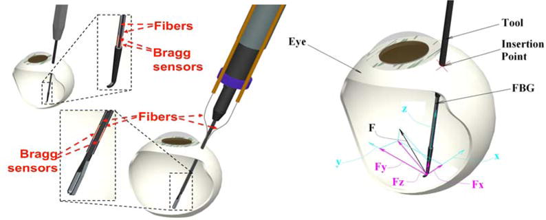
(Left) Conceptual design of optical fiber force sensing tool; (Right) force coordinate system at the tip of the tool
Ultimately, we desire to measure 3 DOF forces resolved at the tip of the surgical instrument. To achieve this, we currently plan to measure translational forces along the tool shaft by embedding 1 DOF force sensing in the tool handle and to place FBG strain sensors along the tool shaft distal to the sclerotomy point. We will use redundant FBG sensors to compensate for errors due to temperature effects, in much the same manner as might be done with conventional electrical strain gauges.
1 DOF FORCE SENSING PROTOTYPE
Design and Fabrication
To mimic 25 gauge ophthalmic instruments, a 50 mm long titanium wire with 0.5mm diameter was prepared as the tool shaft. Titanium was selected to provide the tool the necessary toughness and flexibility to allow maximal strain and resulting increased sensitivity. To integrate the FBG optical fiber into the shaft, a square section channel (160×160 μm) was machined into the surface along shaft’s axial direction. The FBG sensor used here is OS110, from Micron Optics, Inc. (Atlanta, GA), with a central wavelength of 1550nm. The active fiber section of the sensor is about 10mm long, starting 5mm from the tip of the fiber pigtail. An optical sensing interrogator, sm130–700 from Micron Optics Inc. (Atlanta GA), was used to monitor the sensor. The wavelength interrogator has a resolution of 0.001 nm and scan frequency up to 2 kHz, with 4 channels.
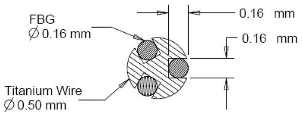
The cross sectional profile of a single FBG sensor and a picture of the prototype are shown in Figure 2. With such a design, the overall size and length of the tool both can meet the design criteria. Calibration testing was performed to determine the force-wavelength relationship and the force measurement resolution.
Figure 2.

1-DOF force sensing tool prototype: Cross Section diagram and lateral view.
Force Resolution Validation
Calibration was carried out in an electrically shielded analytical balance, Sartorius 1601 from Data Weighing Systems, Inc. (Elk Grove IL), which has a readability of 0.1 mg. An acrylic placeholder was placed on the balance below the tool tip. The tool was held horizontally by a pin vise, which was attached to a 3-DOF linear translation stage. The tool was oriented so that the channel with the FBG sensor was either facing upwards or downwards in vertical plane. The tool shaft axis was positioned to be perpendicular to the placeholder’s apex. The setup can be found in Figure 3.
Figure 3.
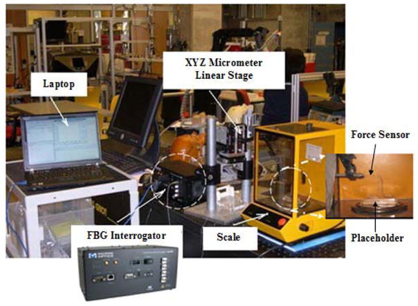
1DOF force sensor system and calibration setup
Through fine adjustment of the height of the vertical translation stage, the force exerted on the shaft tip can be calculated from the weight read from the analytical balance. The resolution of the balance is 0.1mg, which is equivalent to approximately 0.001mN in force for this setup. For every increment of 25mg in weight, the corresponding wavelength of the FBG sensor was recorded. Calibration was performed first with the FBG facing downward and second with the FBG facing upward. By changing the orientation, the surface with the embedded FBG will experience either tension (FBG downward) or compression (FBG upward). The result is shown in Figure 4. It is notable that the results show a linear relationship between the force exerted and the wavelength in both cases, and that the two calibration curves are almost symmetrical.
Figure 4.

Calibration results for 1 DOF force sensing prototype
From the calibration results, we conclude that the force resolution is adequate to meet the design goal of 0.25mN. Our design has met all of the fundamental design criteria to enable us to create a 2-DOF force sensing tool.
2 DOF Force Sensing Tool
Design of the 2D Force Sensor
To measure the force in the transverse plane (perpendicular to Z axis of the tool shaft, see Figure 1), three FBG sensors are embedded evenly along the surface of the wire, 120° from one another. With such a design, the cross section is symmetric as shown in Figure 5; the neutral surface is perpendicular to the applied force and passes through the center of the circle.
Figure 5.
Cross Section diagram of 2-DOF force sensing tool.
It is known that the sensitivity of the FBG sensor is governed by the nature of the load or strain which is applied to the structure the fiber is attached to or embedded within [12]. With a force applied at the tip of the wire, the stress on the cross section of the wire can be described by
where y is the distance from the surface to the neutral surface, R is the radius of the wire, I is the moment of inertia of the wire cross section, M is the moment at the tip, L is the length of the cantilevered shaft, and F is the applied force at the tip. With fixed L and I, the strain on the surface of the wire is proportional to the applied force; then the applied force can be calculated from the stress distribution in the cross section.
Force Computation Algorithm
To calculate the lateral force components (FX and FY in Figure 1) an algorithm is developed to eliminate the axial component and provide cancellation of temperature effect. The shift in Bragg wavelength with strain and temperature can be expressed as:
We assume that there is negligible temperature gradient along the surface of such small volume, so three FBG sensors experience the same ΔT and the temperature sensitivity KT should be constant for the same type of FBG sensors.
Here we introduce a new parameter, ΔS as the sensor reading, which is defined as
By subtracting the mean value from each wavelength shift, the common terms such as noises, axial strain and the temperature component can be removed. From the expression, we could expect a linear relationship between the sensor reading ΔS and the applied force in corresponding x-y coordinates as shown below:
Experimental Setup and Calibration
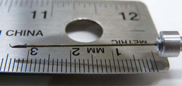
The calibration setup is similar to the previous one, with inclusion of an additional rotary stage to provide an accurate angle adjustment with a resolution of 2 degrees: Figure 6. The coordinate origin was set at the tip of the wire and at the center of the cross section. Initial sensor position with one of the FBG fibers (channel 1) facing up was set to be the x-axis. The calibration was performed by rotating the sensor about its long axis 90 degrees and loading the sensor in 0.25mN steps. Four calibration sets were performed at 0, 90, 180, 270 degrees. Another set of calibrations was performed at 120 degree intervals for consistency and symmetry.
Figure 6.
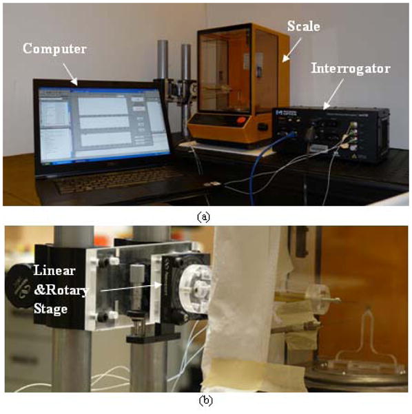
(a) Experiment setup for 2D force sensor (b) Detail inside the scale
The following calibration matrix was obtained:
The force then can be calculated using the sensor readings ΔS and the pseudo-inverse of the calibration matrix:
Results
Temperature Compensation
To evaluate the behavior of the 2DOF force sensor in temperature varying environment, a candle was placed in the enclosure of the scale as a heat source. In the top graph in Figure 7, the wavelength shifts for 3 channels are plotted in blue, red and black over time. The wavelength shifts are the same for each FBG sensor when exposed to the same temperature without any loading. A dramatic wavelength shift change can be observed at time 12 seconds, while the calibrated force components in x-axis and y-axis remain at zero, as observed in the corresponding bottom two graphs. The maximum shift in wavelength due to temperature effect is about 20 picometers, which is equivalent to approximately 2mN based on previous calibration results.
Figure 7.

Test on temperature compensation w/o load
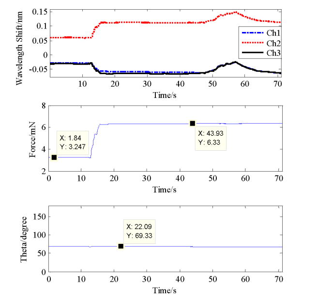
Testing was also done with the load at an arbitrary angle. By adjusting the linear and rotary stages, we changed the force exerted at the tip from 3.25mN to 6.33mN at a direction of about 70 degrees from x-axis. The data collected and calculated force and angle are shown in Figure 8.
Figure 8.
Test on temperature compensation w/ load
For the first 12 seconds, the force was kept at 3.25mN, and then increased to 6.33mN by moving the linear stage to apply a load on the sensor. A candle was placed near the sensor to increasing the temperature which is represented by a peak in wavelengths shift of all FBGs around 50–60 seconds. However, the calculated force is unaffected and the angle calculated based on FX and FY is around 70 degrees during the whole process. It can be concluded that the calibration matrix obtained works very well to evaluate the 2-D force at the wire tip; and the algorithm removes the temperature influence effectively.
Hook Instrument with Force Sensing
Membrane peeling is a clinical task used in the surgical treatment of epiretinal membrane (ERM). Epiretinal membrane is a thin (i.e. 5 μm) “cellophane-like” layer of preretinal cellular elements that forms over inner the surface of the macula. It is generally a slowly progressive problem (months) that affects the central vision by distorting the retinal surface thereby leading to the perception of visual blur and distortion. To improve vision, this membrane is surgically “peeled” off of the retina, the procedure is technically demanding and associated with significant surgical risk. A simple hook or microforceps is often used to engage and delaminate the pathological ERM. With this force sensing tool, a customized hook was built and attached, as shown in Figure 9, to determine whether the force sensor can be incorporated and used in a prototypical vitreoretinal surgical instrument. With essential small size and capability to provide force information, the novel tool has great potential to improve surgical training and performance in the retinal microsurgery. By adding the hook which translates the tool tip and consequently the point of force application, the calibration matrix needs to be regenerated with new force vs. wavelength shift measurements. The new calibration matrix is
Figure 9.
Customized hook
To simulate epiretinal membrane peeling, we peeled and measured the forces generated during peeling of the inner shell membrane (ISM) of a 12 day old chicken embryo and a 3 week old raw egg as shown in Figure 10, and Figure 5 respectively.
Figure 10.

Membrane peeling on the inner shell membrane in chicken embryo
During the data collection the instrument was held close to 90 degrees to the membrane surface in order to minimize the force along the tool axis. The preliminary results show the various force profiles involved in membrane peeling collected and displayed in real time. This capability will allow us to monitor tool tissue interaction forces in membrane peeling experiments. In addition, two experienced surgeons that tested both membrane models favored the raw egg as a good model for future experiments.
Conclusion
This paper has reported a new family of force-sensing microsurgical instruments. We have shown that placing FBG fiber optic force sensors along the shaft of sub-millimeter diameter retinal instruments has sufficient force sensitivity to measure the extremely delicate forces associated with retinal surgery. Since the 10 mm long active element of the FBG sensor is embedded near the tip of the tool, which is completely inside of the eye (25 mm diameter), the tool-to-sclera interaction forces do not affect the sensor readings. Other advantages associated with our force sensing approach include immunity to electrical noise, MRI compatibility, relatively easy to interface and sterilize. Its robustness and versatility due to size are ideal for microsurgical applications.
With the algorithm developed, we have successfully removed the temperature effect from the sensor readings. Only two sets of calibration are required to calculate the calibration matrix. A disadvantage is that the approach removes any forces related to axial strain. Though the sensitivity in measuring the strain in axial direction is much smaller compared to those along the transverse plane, the axial force measurement is still desirable for a complete a 3-DOF force sensing tool. Further investigation of the necessity of the extra DOF and possible solutions is currently in progress.
With the 2DOF sensing instrument presented here, we plan to begin a much more extensive series of studies to measure baseline tool-to-tissue forces during simulated and actual retinal procedures, as well as to develop sensory substitution and force-based robotic virtual fixtures for assisting the surgeon in carrying out these tasks. Examples of the former would include auditory or visual force cues (e.g., on a surgical microscope display). Examples of the latter include force servoing and force limiting behaviors to improve safety.
Figure 5.

Membrane peeling on the inner shell membrane of a raw egg
Acknowledgments
This work was supported in part by the U.S. National Science Foundation under Cooperative Agreement EEC9731748, in part by the National Institutes of Health under BRP 1 R01 EB 007969-01 A1, and in part by Johns Hopkins internal funds.
Zhenglong Sun thanks to his supervisor Asst. Professor Soo Jay (Louis) Phee from Nanyang Technological University, Singapore for sponsoring his stay in US.
Footnotes
Note: The manuscript below represents the accepted review draft of a paper to be published in volume 4, 2009, of the International Journal of Computer Assisted Radiology and Surgery. The electronic version of this paper was published on 15 April 2009, and may be found at the link: http://www.springerlink.com/content/x207x35511840025/?p=4eb1f50891a6449ab04c05003af13ce5&pi=6
In addition to minor corrections made during the process of preparing the paper for publication, the authors changed the order of authors of the paper and added one additional author (Phee).
References
- 1.Patkin M. Ergonomics applied to the practice of microsurgery. Aust NZ J Surg. 1977;47:320–329. doi: 10.1111/j.1445-2197.1977.tb04297.x. [DOI] [PubMed] [Google Scholar]
- 2.Gupta PK, Jensen PS, de Juan E., Jr Surgical forces and tactile perception during retinal microsurgery. MICCAI’99, LNCS 1679. 1999:1218–1225. [Google Scholar]
- 3.Iordachita, et al. Steady-Hand manipulator for retinal surgery. proceedings, MICCAI Medical Robotics Workshop; 2006. [Google Scholar]
- 4.Mitchell B, et al. Development and Application of a New Steady-Hand Manipulator for Retinal Surgery. IEEE Int Conf on Robotics and Automation. 2007:623–629. [Google Scholar]
- 5.Okamura AM. Methods for Haptic Feedback in Teleoperated Robot-Assisted Surgery. Industrial Robot. 2004;31:499–508. doi: 10.1108/01439910410566362. [DOI] [PMC free article] [PubMed] [Google Scholar]
- 6.Zhou Y, Nelson BJ, Vikramaditya B. Fusing force and vision feedback for micromanipulation. Proc IEEE Int Conf Robotics & Automation; Leuven, Belgium. May, 1998. pp. 1220–1225. [Google Scholar]
- 7.Kim K, Sun Y, Voyles R, Nelson B. Calibration of Multi-Axis MEMS force Sensors Using the Shape-From-Motion Method. IEEE Sensors Journal. 2007 March;7(3) [Google Scholar]
- 8.Menciassi, Eisinberg A, Scalari G, Anticoli C, Carrozza MC, Dario P. Force feedback-based microinstrument for measuring tissue properties and pulse in microsurgery. Proc IEEE Int Conf Robotics & Automation; Seoul, Korea. May, 2001. pp. 626–631. [Google Scholar]
- 9.Berkelman PJ, Whitcomb LL, Taylor RH, Jensen P. A miniature microsurgical instrument tip force sensor for enhanced force feedback during robot-assisted manipulation. IEEE Trans Rob Autom. 2003;19(5):917–921. [Google Scholar]
- 10.Berkelman PJ, Whitcomb LL, Taylor RH, Jensen P. A miniature Instrument Tip Force Sensor for Robot/Human Cooperative Microsurgical Manipulation with Enhanced Force Feedback. Medical Image Computing and Computer-Assisted Interventions; Pittsburgh. 2000. pp. 897–906. [Google Scholar]
- 11.Jagtap D, Riviere CN. Applied Force during Vitreoretinal Microsurgery with Handheld Instruments. Proc. 26th IEEE Engineering in Medicine and Biology Conference (EMBS); San Francisco. 2004. pp. 2771–2773. [DOI] [PubMed] [Google Scholar]
- 12.Hill KO, Meltz G. Fiber Bragg grating technology fundamentals and overview. Journal of Lightwave Technology. 1997;15(8):1263–1276. [Google Scholar]