Abstract
We attached a miniature motor rotating at 11,000 rpm onto the proximal end of cardiac electrophysiological (EP) catheters in order to produce vibrations at the tip which were then visualized by color Doppler on ultrasound scanners. We imaged the catheter tip within a vascular graft submerged in a water tank using the Volumetrics Medical Imaging 3D scanner, the Siemens Sonoline Antares 2D scanner, and the Philips ie33 3D ultrasound scanner with TEE probe. The vibrating catheter tip was visualized in each case though results varied with the color Doppler properties of the individual scanner.
Keywords: Color flow Doppler, device guidance, cardiac electrophysiology catheters
I. INTRODUCTION
Most interventional device guidance during minimally invasive procedures is performed using X-ray fluoroscopic imaging. However, x-ray fluoroscopy does not provide the physician good tissue contrast, lacks depth information, and delivers ionizing radiation to the patient and staff. One alternative is the use of ultrasound image guidance, which provides the clinician with excellent soft tissue contrast without ionizing radiation.
However, imaging the device tip is often difficult since it is a specular reflector, which often does not return the ultrasound echoes back to the transducer. Previously, our laboratory and others have used piezoelectric buzzers at the proximal end to produce kHz vibrations along needle like devices enabling guidance of device tips using ultrasound color Doppler. [1-5] The needle tip is a vibration anti-node with motion x = A sin (2πft) and tip velocity v = dx/dt = 2πfA cos (2πft), where A is the amplitude for the vibration frequency (f). Previous analytical modeling showed good agreement with measurements of needle motion for this design. [6]
The analogous problem for cardiac (EP) catheters is more difficult due to the flexible, lossy catheter body surrounding the multiple conductors and steering mechanism. Despite trying a variety of piezoelectric buzzers along with an audio amplifier we were unsuccessful in generating detectable kHz vibrations at the catheter tip. However, by attaching a miniature motor onto the proximal end of a cardiac catheter, we hypothesized that we could induce vibrations at the tip which could then be visualized using color flow Doppler on several ultrasound systems.
II. METHODS
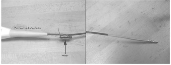
Using epoxy, we attached a high speed miniature motor (11,000 rpm = 183 rps, Jameco Reliapro Mfg, 4.1 mm diameter, 11.2 length) approximately 2 cm from the proximal end of a Boston Scientific Stereoocath-T Model 6303 quadrupolar catheter, (1.46 m long, 8 Fr where 1 Fr = 0.33 mm) normally used for cardiac EP mapping and ablation (Fig. 1a) in order to produce vibrations at the device tip (Fig. 1b). The motor includes a camshaft to produce mechanical vibrations for electronic pager applications. The catheter was then introduced into a 4.8 cm diameter dacron vascular graft through an introducer sheath. The graft was imaged while it was submerged in a water tank during these experiments. The motor was powered by a variable voltage DC power supply (up to 3V) or a single AAA battery.
FIG. 1.
Proximal end of the cardiac EP catheter with vibrating motor attached (left). Catheter tip (right).
We imaged the catheter tip using the Volumetrics Medical Imaging (VMI, Durham NC) real time 3D scanner using a 2.5 MHz transthoracic matrix array, the Siemens Sonoline Antares 2D scanner using a Model VF7-3 linear array operating at 4.2 MHz, and the Philips ie33 3D ultrasound scanner with TEE probe operating at 5 MHz. For each scanner we optimized the color Doppler images by adjusting user controls including echo and Doppler output power, gain, reject, color Doppler scale and baseline. These adjustments altered the Doppler color bar for each image.
III. RESULTS
Figure 2 shows results obtained from the VMI 3D system including simultaneous long axis Bscan (Fig. 2A), short axis B-scan (Fig. 2B) and long axis C-scan (Fig. 2C). Each figure shows the wall of the vascular graft and vibrating catheter tip. Note the color vibrations are strongest at the metal catheter tip. Note also the color reverberations extending below the tip.
FIG. 2.

Color Doppler images of the cardiac EP catheter using the Volumetrics 2.5MHz real-time 3D ultrasound scanner. (A) Long Axis B-mode. (B) Short Axis B-mode. (C) Long Axis C-mode.
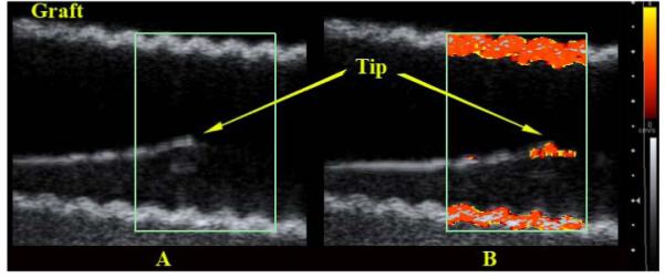
Figure 3 shows the results from the Siemens scanner after carefully aligning the body of the catheter with the transducer plane. The figure compares images with and without the motor. Note that the catheter vibrations are well contained at the tip with little evidence of tip reverberations so that the catheter tip could be easily tracked as it moved through the vascular graft. More striking however are the strong vibrations in the wall of the graft produced by the vibrating catheter and then displayed in color Doppler.
FIG. 3.

Color Doppler images of the cardiac EP catheter using a 4.2 MHz 2D Siemens scanner. (A) Vibrating motor off. (B) Vibrating motor on.
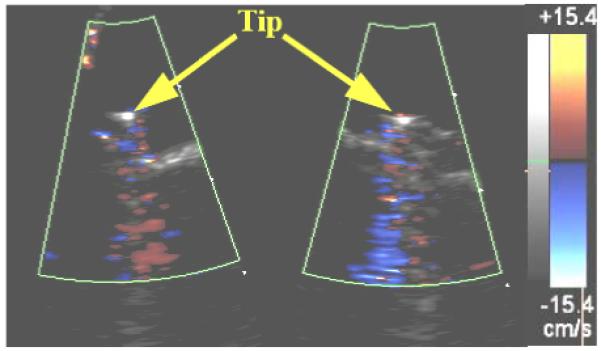
Figure 4 shows the results of the Philips ie33 3D ultrasound scanner with 5 MHz TEE probe. In this case the walls of the vascular graft also showed strong distracting vibrations so the catheter was removed from the graft and imaged in the water tank from two simultaneous oblique planes. Vibrations in the catheter tip are again evident but here the reverberations in the metal tip electrode were strongest producing the distracting color band extending in range below the catheter. Extensive adjustments of color Doppler settings by an experienced sonographer did not eliminate this artifact.
FIG. 4.

Simultaneous oblique color Doppler images of the cardiac EP catheter using a 5.0MHz Philips 3D ultrasound scanner with TEE probe.
IV. DISCUSSION
Using an 11,000 rpm motor attached to the proximal end of a cardiac EP catheter, we were able to produce vibrations at the distal end in order to enable tip detection which may allow ultrasound color Doppler guidance during interventional procedures. However, the strong vibrations caused significant color Doppler image artifacts which varied for each scanner leading us to believe that customized Doppler settings may be necessary to optimize catheter guidance for each catheter and each ultrasound scanner. Note that there two different artifacts. For the VMI and Philips 3D scanners there were significant reverberations in the metal ablation tip of the catheter. For the Siemens 2D scanner the increased color Doppler sensitivity displayed the vibrations present in the wall of the vascular graft. This artifact may not be present in vivo with its increased attenuation.
In addition, further work can be done to determine the optimal motor speed for a catheter of a given length. Perhaps using miniature pager motors, cell phone motors, and/or higher frequency motors will result in a better tip visualization. Also, the placement of the motor at various locations on the catheter and its effects on tip displacement should be considered.
REFERENCES
- 1.Armstrong G, Cardon L, Vilkomerson D, Lipson D, Wong J, Rodriguez LL, Thomas JD, Griffin BP. Localization of needle tip with color Doppler during pericardiocentesis: In vitro validation and initial clinical application. Journal of the American Society of Echocardiography. 2001;14:29–37. doi: 10.1067/mje.2001.106680. [DOI] [PubMed] [Google Scholar]
- 2.Smith SW, Booi RC, Light ED, Merdes CL, Wolf PD. Guidance of cardiac pacemaker leads using real time 3D ultrasound: Feasibility studies. Ultrasonic Imaging. 2002;24:119–128. doi: 10.1177/016173460202400205. [DOI] [PubMed] [Google Scholar]
- 3.Fronheiser MP, Idriss SF, Nelson RC, Lee W, Smith SW. Real time 3D color flow Doppler for guidance of vibrating interventional devices. Ultrasonic Imaging. 2004;26:173–184. doi: 10.1177/016173460402600304. [DOI] [PubMed] [Google Scholar]
- 4.Fronheiser MP, Idriss SF, Wolf PD, Smith SW. Vibrating interventional device detection using real-time 3-D color Doppler. IEEE Trans Ultrason Ferroelec and Freq Contr. 2008;55:1355–1362. doi: 10.1109/TUFFC.2008.798. [DOI] [PMC free article] [PubMed] [Google Scholar]
- 5.Klein SM, Fronheiser MP, Reach J, Nielsen KC, Smith SW. Piezoelectric vibrating needle and catheter for enhancing ultrasound-guided peripheral nerve blocks. Anesthesia and Analgesia. 2007;105:1858–1860. doi: 10.1213/01.ane.0000286814.79988.0a. [DOI] [PubMed] [Google Scholar]
- 6.Fronheiser MP, Smith SW. Analysis of a vibrating interventional device to improve 3-D Colormark tracking. IEEE Trans Ultrason Ferroelec and Freq Contr. 2007;54:1700–1707. doi: 10.1109/tuffc.2007.442. [DOI] [PubMed] [Google Scholar]


