Abstract
The synthesis of a new kind of magnetic, fluorescent multifunctional nanoparticles (~30 nm in diameter) was demonstrated, where multiple fluorescent CdTe quantum dots (QDs) are covalently linked to and assembled around individual silica-coated superparamagnetic Fe3O4 nanoparticles and active carboxylic groups are presented on the surface for easy bioconjugation with biomolecules. The Fe3O4 nanoparticles were firstly functionalized with thiol groups, followed by chemical conjugation with multiple thioglycolic acid modified CdTe QDs to form water-soluble Fe3O4/CdTe magnetic/fluorescent nanocomposites. X-ray diffraction, infrared spectroscopy, transmission electron microscopy, absorption and fluorescence spectroscopy, and magnetometry were applied to fully characterize the multifunctional nanocomposites. The nanocomposites were found to exhibit magnetic and fluorescent properties favorable for their applications in magnetic separation and guiding as well as fluorescent imaging. The carboxyl groups on the nanocomposite surface were proved to be chemically active and readily available for further bioconjugation with biomolecules such as bovine serum albumin and antibodies, enabling the applications of the nanocomposites for specific recognition of biological targets. The Fe3O4/CdTe magnetic/fluorescent nanocomposites conjugated with anti-CEACAM8 antibody were successfully employed for immuno-labeling and fluorescent imaging of HeLa cells.
Keywords: Fe3O4 magnetic nanoparticles, quantum dots, multifunctional nanoparticles, Hela cells, immuno-labeling, fluorescence imaging
1. Introduction
Over the past two decades, great attention has been paid to superparamagnetic iron oxide nanoparticles such as magnetite (Fe3O4) and maghemite (γ-Fe2O3).1 Iron oxide nanoparticles especially magnetite (Fe3O4) are the most prominent class of MNPs that can be applied in drug delivery and biosensing,2 dynamic sealing3 and magnetic resonance imaging.4, 5 Recently increasing attention has been paid to the fabrication of bifunctional nanostructures consisting of discrete domains of two materials.6 Among such nanostructures, a nanocomposite integrating both magnetic and fluorescent properties can be applied in a variety of fields such as fluorescent detection, magnetic separation and bioassay. For example, Yu and coworkers 7 incorporated the fluorescent dyes onto silica shells through a covalent coupling between these organic dyes and the silica coated magnetic nanoparticles for the first time in 2002.
Quantum dots (QDs) have been actively studied for bio-imaging applications due to their excellent optical properties such as narrow emission bands, continuous broad absorption band and high resistance to photo bleaching in comparison with organic dyes.8 Therefore, great efforts have been made to incorporate magnetic nanoparticles and QDs instead of organic dyes in synthesizing magnetic and fluorescent nanocomposites.9 A layer-by-layer (LbL) approach was developed to prepare water-soluble magnetic luminescent nanocomposites by using Fe3O4 as a core and QDs as a shell.10 The LbL approach was based on the electrostatic attraction between the modified magnetic cores and QDs and the distance between Fe3O4 and QDs could be controlled by the LbL approach in order to prevent the quenching effect of Fe3O4.11 Some researches presented seeded growth methods to synthesize more stable magnetic fluorescent multifunctional nano-architectures.12, 13 For instance, in 2007, Fe3O4 nanowires decorated by CdTe 14 were synthesized by using ethylenediamine as a template. Some researches embedded magnetic nanoparticles and QDs into one silica shell, however, the resultant nanocomposite particles were larger (usually of 70 to 200 nm) and the reagents such as polyelectrolytes used in their work were expensive.15 Therefore, covalently linking magnetic and fluorescent components is highly desired in biomedical applications of the magnetic/fluorescent nanoparticles in order to increase the stability of the nanocomposites as a whole in biological media.16, 17 For example, polymer coated γ-Fe2O3 and CdSe/ZnS were integrated through thiol coordination and the resultant composite nanoparticles were successfully conjugated with MCF-7 breast cancer cells.16 So far, there has been no report about covalently coupling Fe3O4@SiO2 and TGA modified CdTe and their applications in labeling HeLa cells.
In this work, we propose a new method for the synthesis of water-soluble magnetic and fluorescent nanocomposites, where multiple thioglycolic acid (TGA) stabilized CdTe QDs were covalently linked with and assembled around individual thiol-functionalized silica-coated Fe3O4 core-shell nanoparticles (Figure 1). The magnetic nanoparticles of Fe3O4 were first coated with silica shells through sol-gel method and then functionalized with thiol groups. Then multiple TGA-stabilized CdTe QDs were conjugated with the surface of the thiol-functionalized silica-coated Fe3O4 core-shell nanoparticles to form nanocomposites through reaction between thiols on QDs and silica. The fluorescence intensity of the as-synthesized Fe3O4/CdTe magnetic/fluorescent nanocomposites was comparable to that of the pure CdTe QDs. It is proved in our experiment that the moderate saturation magnetization of the magnetic/fluorescent nanocomposites could insure the magnetic separation by using a magnet. Meanwhile, the carboxylic groups on the nanocomposite surface, introduced due to the presence of the TGA on the CdTe QDs, were chemically reactive to enable the conjugation between the nanocomposite particles with biomolecules such as anti-CEACAM8. As a result, the Fe3O4/CdTe nanocomposites were used as fluorescent probes to label and image HeLa cells successfully (Figure 1). Our results indicate that the magnetic/fluorescent nanocomposites may be applied for targeted drug delivery, bioimaging, as well as bioseparation by a single material.
Figure 1.
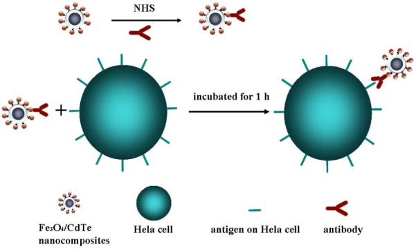
Schematic illustration of immuno-labeling using Fe3O4/CdTe nanocomposites which are formed by linking multiple TGA-stabilized CdTe QDs with the thiol-functionalized silica-coated iron oxide nanoparticles.
2. Experimental
2.1 Materials
Thioglycolic acid (TGA), sodium borohydride and tellurium powder were purchased from the Shanghai Chemicals Company in China. CdCl2·2.5H2O was obtained from the Peking Chemical Plant. 3-mercatopropyl-trimethosysilane (MPS) was purchased from Lancaster (95%). Absolute ethanol, PEG 4000, aqueous amminia (25%), acetone, citric acid and TEOS were purchased from National Medicines Corporation Ltd. of China. Bovine serum albumin (BSA) was from AOBO Biology Techniques Company in Beijing, China. N-Hydroxysuccinimide (NHS) was received from Acros Organics, NJ, USA. Anti-CEACAM8 (CD67) was from Beijing Biosyhthesis Biotechnology Co. Ltd. Ferric chloride and ferrous chloride were from Tianjin Bodi Chemicals Co. Ltd. Hela cells were supplied by China Medical University. All chemicals, used in the experiments, were of high purity and commercially available without further purification. Double distillated water was used through out the experiments.
2.2 Characterization
The powder X-ray diffraction (pXRD, PW3040/60 X’Pert Pro MDP, Holland Panalytical B. V.) was carried out at room temperature by using CuKα (1.5418 Å) radiation. Fourier transform infrared (FT-IR) spectra were recorded by Perkin Elmer Spectrum One spectrometer. JEM-2100HR transmission electron microscope (TEM, JEOL Ltd., Japan), using an accelerating voltage of 200 kV, was used to characterize the nanoparticles. The hysteresis loops were obtained with vibrating sample magnetometer (VSM 7407, LakeShore, USA). The fluorescence emission spectra were measured on a LS-55 Luminescence Spectrometer (Perkin-Elmer, USA) with 350 nm excitation. Absorption spectra were recorded on a UV-2100 UV-vis spectrometer (Rui Li Analytical Instrument Company, Beijing, China). The pH measurements were made with a PHS-3C pH meter (Hangzhou, China). All optical measurements were carried out at room temperature under ambient conditions. During the conjugation between nanoparticles and BSA and anti-CEAcam8, the mixture was incubated by the CHA-S Reciprocating Oscillator (Jintan, Jiangshu, China).
2.3 Preparation of iron-oxide magnetic nanoparticles
Iron-oxide Fe3O4 magnetic nanoparticles were prepared through an improved chemical co-precipitation method.17 Briefly, a solution of mixture of FeCl3 (1.0 M) and FeCl2 (1.0 M) with a molar ratio of 5:3 (Fe2+ + Fe3+=16 mM) together with 150ml water and 10.0 g PEG4000 was prepared with agitation under N2 protection in a three-necked flask of 250 ml. Then a concentrated NH3 aqueous solution (25 wt. %) was added dropwise slowly to the flask until the pH value of the solution reached 9.5 ± 0.1. After reaction at 40°C for 30 min under mechanical stirring and N2 protection, the PEG4000 modified Fe3O4 solid precipitations were magnetically separated, washed with water for dozens of times until the pH value reached 7.0, and finally dried at 40 °C for 48 h.
In order to get better dispersibility, the obtained PEG4000 modified Fe3O4 magnetic nanoparticles were modified by citric acid again as reported.18 Briefly, 0.5 g PEG4000 modified Fe3O4 nano-particles were diluted in 100 ml 0.5 M citric acid. After ultrasonic treatment at room temperature for 4.0 h under mechanical stirring, the obtained mixture was centrifuged at 9000 rpm to remove large and aggregated particles. Then the colloidal Fe3O4 nanoparticles were washed with acetone for 4 times and finally dried at 40 °C for 1 h.
2.4 Preparation of CdTe QDs
The CdTe QDs was synthesized using the reaction between Cd2+ and NaHTe solution following a method described previously,19 with TGA as a stabilizing agent. Briefly, the sodium borohydride was reacted with tellurium powder (3:1 molar ratio) in water to produce NaHTe. The molar ratio of Cd2+:Te2-:TGA of 1:0.5:2.4 was used. The fluorescence of the CdTe crystals could be tuned in color (green, yellow, orange, or red) by changing the heating time (70min, 110min, 130min, or 170min) at 140 °C.
2.5 Synthesis of magnetic/fluorescent nanocomposites
2.5.1 Preparation of Fe3O4@SiO2-SH nanocomposites
Fe3O4 nanoparticles were first coated with silica by Stober method for further synthesis of magnetic/fluorescent nano-composites. First, 20 mg citric acid modified Fe3O4 powder, 20 ml water, 2.5 ml ammonia solution and 50 ml ethanol were added to a three-necked flask of 250 ml. After sonication and mechanical stirring at room temperature for 30 min, TEOS together with 30 ml ethanol was added dropwise slowly to the flask. Different amounts of TEOS were added in order to tune silica shell thickness. After reaction for 8.0 h at 35 °C under continuous stirring, MPS in different amounts and 10 ml ethanol were added dropwise into the flask. The reaction was lasted for 12 h at 35 °C. The resultant Fe3O4@SiO2-SH nanocomposites were then stored prior to further use.
2.5.2 Synthesis of Fe3O4/CdTe magnetic/fluorescent nanocomposites
The thiol-functionalized Fe3O4@SiO2 nanoparticles were conjugated with the as-prepared TGA-functionalized CdTe QDs through bonding between thiols on QDs and silica. In brief, 5 ml of as-synthesized TGA-stabilized CdTe QDs were added to 20 ml functionalized Fe3O4@SiO2 aqueous solution with agitation under N2 protection in a three-necked flask of 100 ml. Then a 3.0 M NaOH aqueous solution was added dropwise to the flask until the pH value of the solution reached 11.0±0.1. After reaction at room temperature for 6.0 h under mechanical stirring and N2 protection, the magnetic/fluorescent nanocomposites were successfully collected and purified by using a magnet.
2.6 Conjugation of Fe3O4/CdTe Magnetic/Fluorescent Nanocomposites with BSA
The as-synthesized Fe3O4/CdTe magnetic/fluorescent nanocomposites were magnetically separated to remove the free TGA molecules and Cd2+, followed by resuspension in water to form a colloidal solution under ultrasonic agitation. 100 μL of Fe3O4/CdTe nanocomposites was conjugated with different amounts of BSA using NHS as a cross linker in a PBS buffer (pH 7.4). The fluorescence spectra of the nanoparticles before and after conjugation were measured with 350 nm excitation by the slit width of excitation and emission of 15 and 10 nm, respectively.
2.7 Direct labeling of HeLa cells using antibody-functionalized Fe3O4/CdTe nanocomposites
The water soluble Fe3O4/CdTe composite nanoparticles were purified and re-dissolved in water, and then conjugated with the anti-CEAcam8, which is an antibody recognizing CEACAM8 receptor on the Hela cell membrane, using NHS as a crosslinker. The schematic diagram was shown in Fig. 1. Typically, 50 μl of 0.10 mg/ml anti-CEACAM8 solution in 10 mM PBS of pH 7.4, and 50 μl of 100 μg /ml NHS were mixed with 200 μl as-purified water soluble Fe3O4/CdTe in a PBS buffer (pH 7.4), followed by incubation for 1.0 h at 37 °C in a reciprocating oscillator. Then Hela cells were incubated with antibody-functionalized Fe3O4/CdTe nanocomposite nanoparticles at 37 °C for 1.0 h. The cells were cultured (37 °C, 5% CO2) on glass chamber slides in RPMI 1640 media containing 10% fetal bovine serum and 1% penicillin/streptomycin overnight in a culture box. After being washed with PBS for 4 times, the cells were imaged using an inverted fluorescent microscope (Olympus IX51, blue excitation). In a control experiment, Fe3O4/CdTe without antibody conjugated was allowed to interact with Hela cells directly using the same method described above. The whole labeling process was quite similar with that of the pure QDs.20
3 Results and discussion
3.1 Structure characterization of the nanoparticles
3.1.1 X-ray diffraction
The X-ray diffraction (XRD) was used to characterize the crystal structure of the as-synthesized nanoparticles and the XRD patterns are illustrated in Figure 2 (a-d). All of the diffraction peaks in Figure 2 (a) can be indexed and assigned to the cubic structure of Fe3O4, which is in good agreement with the theoretic values (JCPDS card: 01-088-0315). A strong and broad peak around 2θ = 20-25° corresponding to amorphous phase of silica (JCPDS card: 01-082-1554) can be seen obviously in Figure 2 (b), and all of the other peaks in Figure 2 (b) can be assigned to the as-synthesized Fe3O4 phase as shown in Figure 2 (a), indicating that the amorphous silica was successfully coated on the surface of Fe3O4. Figure 2 (c) illustrates a typical XRD pattern of CdTe QDs prepared by hydrothermal method which can be indexed to the cubic structure of CdTe (JCPDS card: 01-075-2086). The size of CdTe was calculated to be about 2.17 nm in diameter by using the Debye-Scherrer equation:
where D (in nm) is the size of nanocrystal, λ is the wavelength (in nm) emitted by the x-ray source (λ =0.154178 nm in our experiment), 2θ is the angle at which the peak is observed, and B (in radian) is the full width at half maximum of the peak given by the XRD pattern.
Figure 2.
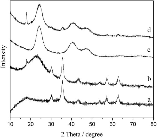
XRD patterns of Fe3O4 nanoparticles (a), Fe3O4@SiO2 nanoparticles (b), CdTe QDs (c), and Fe3O4/ CdTe nanocomposites (d)
The pattern of the final Fe3O4/CdTe magnetic/fluorescent nanocomposites shown in Figure 2 (d) can be indexed by considering that the material is a mixture of Fe3O4, SiO2 and CdTe. Additionally, the peaks of Fe3O4 in the pattern are much weaker than those of CdTe phase, due to the core/shell structure of Fe3O4/CdTe and the larger proportion of CdTe in the final nanocomposites.
3.1.2 Infrared spectroscopy
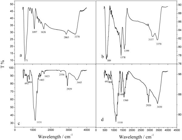
Infrared (IR) spectra were recorded and used to identify the changes of the functional groups on the nanoparticles at different synthetic steps. The strong peak at 571 cm-1 in Figure 3 (a) shows the formation of iron oxides in the experiment. The peak at 1097 cm-1 assignable to the stretching vibration of C-O, those at 1646 cm-1 and 2865 cm-1 assignable to the C-H bend vibration and that at 3370 cm-1 assignable to the O-H stretching vibration band together verify that the PEG4000 has been successfully bound to the surface of the as-synthesized Fe3O4 nanoparticles. The oxidization of the nanoparticles can be prevented due to the protection of PEG4000 on the surface of iron oxides.21 The two peaks at 1399 cm-1 and 1578 cm-1 in Figure 3 (b) are corresponding to the stretching vibration of carboxyl salt, which indicates that the citric acid has been successfully bound to the surface of the Fe3O4 nanoparticles. The peaks at 3157 and 3416 cm-1 might be the stretching vibration of O-H bond in water. The peak at 2556 cm-1 in Figure 3 (c) implies the existence of -SH after the hydrolysis of MPS. Meanwhile there was an obvious shift for the peak assignable to Si-O bond at 1131 cm-1 which indicates existence of electron withdrawing group of -SH after the hydrolysis of MPS. As shown in Figure 3 (d), the peak assignable to -SH of Fe3O4@SiO2 disappears after linking of thiol-modified Fe3O4 with TGA-stabilized CdTe QDs due to the formation of S-S bond which has characteristic IR absorption around 550-430 cm-1. Moreover, the peaks at 1400 and 1560 cm-1 corresponding to the stretching vibration of carboxyl salt are found, which indicates the presence of carboxyl groups on the surface of the final products (i.e., Fe3O4/CdTe magnetic/fluorescent nanocomposites). As the shell of the nanocomposites, CdTe QDs were modified by TGA molecules, which were the origin of the carboxyl groups on Fe3O4/CdTe nanocomposites.
Figure 3.
IR spectrum of Fe3O4-OH nanoparticles (a), Fe3O4-COOH nanoparticles (b), Fe3O4@SiO2-SH nanoparticles (c), and Fe3O4/ CdTe nanocomposites (d)
3.1.3 Transmission electron microscopy
Transmission electron microscopy (TEM) images of these nanoparticles are shown in Figure 4. The citric acid stabilized Fe3O4 magnetic nanoparticles are approximately spherical and the mean size is about 9 nm according to Figure 4 (a). Figure 4 (b) clearly shows the core/shell structure of Fe3O4@SiO2 nanoparticles with an average size of 25 nm. The thickness of silica shell in the core/shell structure is about 15 nm and can be decreased by decreasing the amount of TEOS used during the synthesis. As shown in Figure 4 (b), all of the iron oxide nanoparticles are well coated by the silica shell through the hydrolysis of TEOS on Fe3O4 magnetic particles by the well-known Stober method. Some magnetic nanoparticles are encapsulated inside a common silica shell. It can be observed clearly in Figure 4c that CdTe QDs are in good size distribution and the mean size was 2-3 nm, which was consistent with the diameter calculated by using the Debye-Scherrer equation. TEM images of Fe3O4/CdTe nanocomposites are illustrated in Figure 4d and 4e, and a higher magnification image of the particle in the red circle in Figure 4d is shown in Figure 4e. Figure 4 (d, e) confirms the structure of Fe3O4/CdTe nanocomposite nanoparticles. Namely, multiple smaller CdTe QDs are coated around the surface of an individual silica-coated Fe3O4 core-shell nanoparticle to form a composite structure (CdTe QDs/silica shell/Fe3O4 core) due to the formation of disulfide bond between the thiols on QDs and silica. The final Fe3O4/CdTe magnetic/fluorescent nanocomposites highlighted in the red circle in Fig. 4d are about 30nm in diameter.
Figure 4.
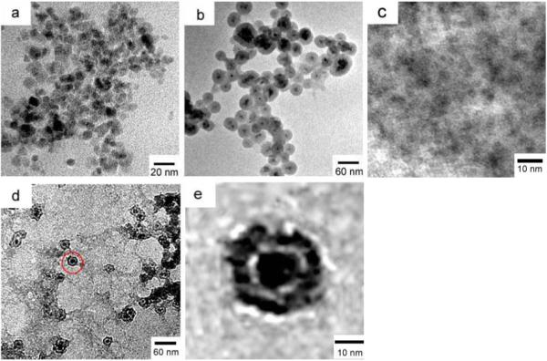
TEM images of Fe3O4-COOH nano-particles (a), Fe3O4@SiO2 nanoparticles (b), CdTe QDs (c) and Fe3O4/ CdTe nano-composites (d, e). (e) is the enlarged view of the area highlighted by a red circle in (d) showing the presence of multiple tiny dots around an individual silica-coated iron oxide nanoparticle.
3.2 Magnetic property of the nanoparticles and nanocomposites
Figure 5 shows the hysteresis loops of the citric acid stabilized Fe3O4 nano-particles (a), Fe3O4@SiO2 nano-particles (b) and the Fe3O4/CdTe magnetic/fluorescent nanocomposites. When the magnetic field is cycled between -15 and 15 KG, zero coercivity is obtained, which indicates the superparamagnetic properties of the as-prepared magnetic nanoparticles. Moreover, Figure 5 (a) demonstrates that the saturation magnetization (Ms) of the citric acid stabilized Fe3O4 nanoparticles with the diameter of about 9 nm is 40.97 emu/g. The value of Ms of silica-coated Fe3O4 is decreased to 9.90 emu/g due to the formation of a silica shell on the surface of Fe3O4, and further decreased to 2.26 emu/g after the CdTe QDs are coated on the surface of Fe3O4@SiO2 nanoparticles. These phenomena can be explained by the diamagnetic contribution of the silica shell and the CdTe QDs surrounding the Fe3O4 magnetic core nanoparticles.22
Figure 5.
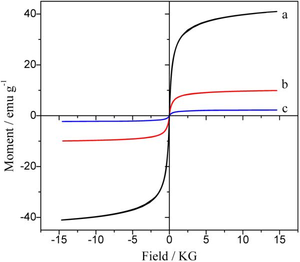
Hysteresis loops for the Fe3O4-COOH nanoparticles (a), Fe3O4@SiO2 nanoparticles (b), and Fe3O4/ CdTe nanocomposites (c)
Figure 6 illustrates the magnetic separation and re-dispersion process of the Fe3O4/CdTe nanocomposites under normal light and 365 nm excitation. As shown in Figure 6, in the absence of an external magnetic field, the solution of the as-synthesized Fe3O4/CdTe nanocomposites is orange and the nanoparticles are well dispersed in the aqueous solution under both normal light and UV irradiation. When a magnetic field is placed near the solution, the nanocomposite nanoparticles are attracted and accumulated towards the magnet, and the bulk solution becomes a clear phase, indicating that magnetic separation occurs. After the magnet was removed and followed by vigorous stirring, the aggregated magnetic/fluorescent nanocomposites can be quickly re-dispersed in water. These results suggest that our nanocomposites can find potential applications in magnetic guiding and separation.
Figure 6.
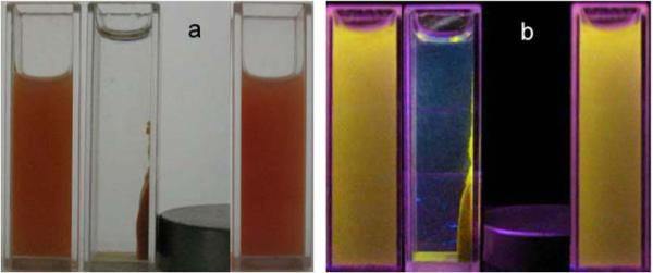
Photographs of aqueous solution of the as-synthesized Fe3O4/CdTe nanocomposites without applying a magnetic field (left), and with a magnetic field (middle), and after removing magnetic field and stirring (right) under normal light (a) and 365 nm excitation (b).
3.3 Absorption and fluorescent spectra
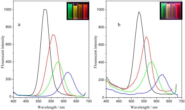
The UV absorbance and fluorescence emission spectra of Fe3O4/CdTe magnetic/fluorescent are shown in Figure 7. As control experiments, the absorption and emission spectra of pure CdTe QDs before being coated on the silica-coated iron oxide nanoparticle surface are also shown. As shown in Figure 7, compared with pure CdTe QDs, the absorption spectrum of Fe3O4/CdTe nanocomposite is quite broad, which is the characteristics of iron oxides. Meanwhile the characteristic absorption band of CdTe QDs becomes less pronounced after covalent bonding with Fe3O4@SiO2-SH to form Fe3O4/CdTe nanocomposites, which can be attributed to the broad and strong absorbance of iron oxides. However, there is no obvious difference in emission spectra between the pure CdTe QDs and the Fe3O4/CdTe magnetic/fluorescent nanocomposites dispersed in water.
Figure 7.
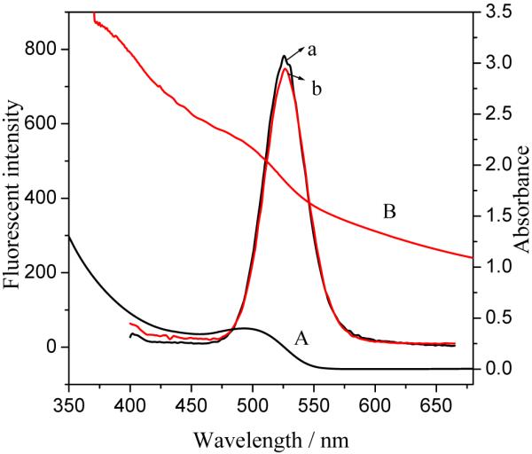
Absorbance and fluorescence emission spectra of CdTe QDs before (a, A) and after (b, B) they are covalently bound to the silica-coated iron oxide nanoparticles to form Fe3O4/CdTe nanocomposites
Figure 8A and 8B show the fluorescence spectra of CdTe QDs with different colors before and after they are coated on the silica-coated iron oxide nanoparticles to form Fe3O4/CdTe magnetic/fluorescent nanocomposites, respectively. The emission peak of Fe3O4/CdTe nanocomposites almost remains as symmetric as that of the pure CdTe QDs. Meanwhile, the colors of pure CdTe and Fe3O4/CdTe nanocomposites under 365 nm irradiation are very similar (Fig. 8 insets). From the optical and magnetic properties of the nanocomposites, it can be concluded that the Fe3O4/CdTe nanocomposites show strong fluorescent emission and desired superparamagnetic properties, which enables them to serve as multi-functional nanoparticles with promising applications in biomedicine.
Figure 8.
Fluorescence emission spectra of CdTe QDs with four different colors before (a) and after (b) they are bound to silica-coated to iron oxide nanoparticles to form Fe3O4/CdTe nanocomposites
3.4 Application of multifunctional nanocomposites in immuno-labeling and fluorescent imaging of HeLa cells
3.4.1 Conjugation between Fe3O4/CdTe nanocomposites and BSA
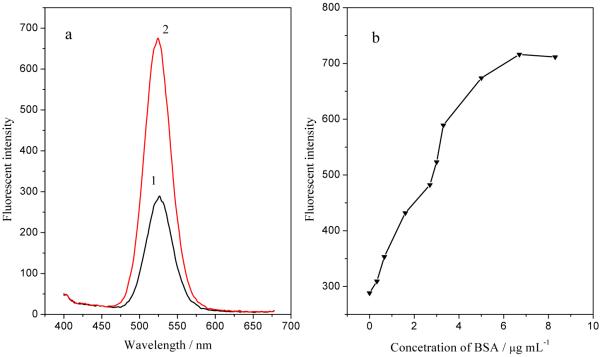
BSA was conjugated with Fe3O4/CdTe magnetic/fluorescent nanocomposites in order to prove that the carboxyl groups on the Fe3O4/CdTe nanocomposites are chemically active and available for bioconjugation with a protein. Figure 9 (a) compares the fluorescent spectra of Fe3O4/CdTe-BSA with that of Fe3O4/CdTe alone. An obvious enhancement can be seen in the fluorescence after BSA conjugation, which indicates that BSA has been successfully conjugated with the Fe3O4/CdTe nanocomposites. The increase in emission intensity after BSA conjugation may be attributed to the inhibition of non-radiative recombination of the surface vacancies of CdTe QDs in Fe3O4/CdTe nanocomposites, similar to the case for pure CdTe QDs.23 Figure 9 (b) shows the fluorescence intensity of Fe3O4/CdTe-BSA in the presence of BSA with different concentrations (0-9.0μg/ml). The fluorescent intensity increases along with the increase of BSA concentration from 0 to 6.7 μg/ml and remains almost unchanged after the concentration of BSA is above 6.7 μg/ml, which may be due to the saturation of the carboxyl groups by BSA at higher concentrations. This result further confirms that the carboxyl groups on Fe3O4/CdTe fluorescent/magnetic nanocomposites are chemically active and available for bioconjugation reaction with a protein such as an antibody, enabling the application of the nanocomposites for labeling living cells for bio-imaging and separation.
Figure 9.
Fluorescence spectra (a) of Fe3O4/CdTe magnetic/fluorescent nanocomposites in the absence (curve 1) and presence (curve 2) of BSA (5μg/ml) and the fluorescence intensity of the emission peak of the Fe3O4/CdTe nanocomposites at different BSA concentration (b).
3.4.2 Cellular imaging
HeLa cells were directly labeled through specific recognition between the CEACAM8 receptor on the cell membrane and the anti-CEACAM8 antibody conjugated with the Fe3O4/CdTe nanocomposite surface. The conjugation chemistry used for linking the antibody to the nanocomposite is same as that for linking BSA as described above. Figure 10 (a) indicates that HeLa cells alone almost do not show any green fluorescence (at 488 nm) under UV radiation. As shown in Figure 10 (c), however, when the Fe3O4/CdTe nanocomposites conjugated with anti-CEAcam8 antibody were interacted with the living HeLa cells, the cells were successfully fluorescently labeled and imaged. These results suggest that through the immuno-reaction of antigen and antibody, the Fe3O4/CdTe-antibody conjugates can be successfully presented on the surface of HeLa cells membrane. In a control experiment, where the Fe3O4/CdTe nanocomposites without antibody conjugated are incubated with the cells, the cells fluorescence little green light (Fig. 10b). This fact indicates that the interaction between the carboxyl groups on Fe3O4/CdTe nanocomposites and the antigens on the cell membranes will not influence the immuno-labeling of the cells using antibody-conjugated nanocomposites. Meanwhile, it seems that due to the toxicity of CdTe QDs in Fe3O4/CdTe multifunctional nanoparticles, the two cells in the bottom of Fig.10c were almost dead. The study on minimizing the cell toxicity of the new multifunctional nanoparticles is now underway.
Figure 10.
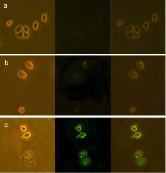
Images of live Hela cells (a) without interacting with any nanoparticles, (b) directly labeled by Fe3O4/CdTe nanocomposites without antibody conjugated and (c) immuno-labeled by Fe3O4/CdTe nanocomposites conjugated with anti-CEAcam8. In the three panels, the left rows represent the phase-contract images, the central rows represent the fluorescent images, the right rows are the overlays of the left and central rows.
It has been well established that superparamagnetic nanoparticles can be applied for targeted delivery of drug24 and gene25 when the drugs or genes are loaded onto the nanoparticles. When such nanoparticles are integrated with fluorescent quantum dots to form nanocomposites, the resultant nanocomposites will bear at least two highly desired functions in biomedicine: the magnetic properties that enable the magnetically guided delivery of drugs and genes and the fluorescent properties that enable the optical imaging of the nanocomposites. As a result, such nanocomposites can be applied to optically trace the delivery of the drugs or genes into cells or tissues. Moreover, when the cell-targeting peptides or organ-homing peptides identified by phage display technique 26 are conjugated to the Fe3O4/CdTe nanocomposites, the nanocomposites will be able to recognize specific cell types or organs, enabling the in vitro or in vivo optical imaging and magnetic guiding of the delivery of the therapeutics by the nanocomposites. This direction is now being explored by our groups.
4 Conclusion
A new kind of magnetic fluorescent multifunctional nanocomposites was prepared by chemically conjugating individual thiol-functionalized silica-coated Fe3O4 nanoparticles with multiple TGA modified CdTe QDs. The multifunctional nanocomposites exhibited favorable magnetic and fluorescent properties and the carboxyl groups presented on their surface were chemically reactive and available for bioconjugation with proteins such as antibodies. Furthermore, the antibody-functionalized nanocomposites were successfully applied to label Hela cells for fluorescent imaging. Therefore, the Fe3O4/CdTe nanocomposites are expected to find potential applications in magnetically guiding and optically tracking the delivery of drugs and gene.
Acknowledgements
We are grateful for the support from the National Science Foundation of China (Grant Nos 20875011 and 20635010) and the Education Committee of Liaoning Province of China. C.B.M. would also like to thank U.S. National Science Foundation, National Institutes of Health, Department of Defense Congressionally Directed Medical Research Programs and Oklahoma Center for the Advancement of Science and Technology for financial support.
References
- (1).Wang X, Wang LY, He XW, Zhang YK, Chen LX. Talanta. 2009;78:327. doi: 10.1016/j.talanta.2008.11.024. [DOI] [PubMed] [Google Scholar]
- (2).Zhang Y, Kohler N, Zhang MQ. Biomaterials. 2002;23:1553. doi: 10.1016/s0142-9612(01)00267-8. [DOI] [PubMed] [Google Scholar]
- (3).Shen LF, Laibinis PE, Hatton AT. Langmuir. 1999;15:447. [Google Scholar]
- (4).Chen ZL, Sun Y, Huang P, Yang XX, Zhou XP. Nanoscale Res Lett. 2009;4:400. doi: 10.1007/s11671-009-9254-5. [DOI] [PMC free article] [PubMed] [Google Scholar]
- (5).Zhao YB, Qiu ZM, Huang JY. J. Chem. Eng. 2008;16:451. [Google Scholar]
- (6).Pellegrino T, Fiore A, Carlino E, Giannini C, Cozzoli PD, Ciccarella G, Respaud M, Palmirotta L, Cingolani R, Manna L. J. Am. Chem. Soc. 2006;128:6690. doi: 10.1021/ja0607741. [DOI] [PubMed] [Google Scholar]
- (7).Yu L, Yin YD, Mayers BT, Xia YD. Nano Lett. 2002;2:183. [Google Scholar]
- (8).(a) Li HB, Zhang Y, Wang XQ, Xiong DJ, Bai YQ. Mater. Lett. 2007;61:1474–1477. [Google Scholar]; (b) Ferandes-Arguelles MT, Jin WJ, Costa-Fernadez JM, Pereiro R. Anal. Chim. Acta. 2005;549:20. [Google Scholar]
- (9).Corr YK, Gun’ko SA, Gun’ko YK, Rakovich YP. Nanoscale Res Lett. 2008;3:87. [Google Scholar]
- (10).Hong X, Li J, Wang MJ, Xu JJ, Guo W, Li JH, Bai YB, Li T. J. Chem. Mater. 2004;16:4022. [Google Scholar]
- (11).Li L, Choo ESG, Liu ZY, Ding J, Xue JM. Chemical Physics Letters. 2008;461:114. [Google Scholar]
- (12).Romlan DG, May SJ, Zheng JG, Allan JE, Wessels BW, Lauhon L. J. Nano Letters. 2006;6:50. doi: 10.1021/nl0519276. [DOI] [PubMed] [Google Scholar]
- (13).Kim H, Achermann M, Balet LP, Hollingsworth JA, Klimov VI. J. Am. Chem. Soc. 2005;127:544. doi: 10.1021/ja047107x. [DOI] [PubMed] [Google Scholar]
- (14).Lan XM, Cao XB, Qian WH, Gao WJ, Zhao C, Guo Y. Journal of Solid State Chemistry. 2007;180:2340. [Google Scholar]
- (15).(a) Kim J, Lee JE, Lee JW, Yu JH, Kim BC, An KJ, Hwang YS, Shin CH, Park JG, Kim JB, Hyeon T. J. Am. Chem. Soc. 2006;128:688. doi: 10.1021/ja0565875. [DOI] [PubMed] [Google Scholar]; (b) Law WC, Yong KT, Roy I, Xu GX, Ding H, Bergey EJ, Zeng H, Prasad PN. J. Phys. Chem. C. 2008;112:7972. [Google Scholar]; (c) Sathe TR, Agrawal A, Nie SM. Anal. Chem. 2006;78:5627–5632. doi: 10.1021/ac0610309. [DOI] [PubMed] [Google Scholar]; (d) Yi DK, Selvan ST, Lee SS, Papaefthymiou GC, Kundaliya D, Ying JY. J. Am. Chem. Soc. 2005;127:4990. doi: 10.1021/ja0428863. [DOI] [PubMed] [Google Scholar]; (e) Guo J, Yang WL, Wang CC, He J, Chen JY. Chem. Mater. 2006;18:5554. [Google Scholar]; (f) Salgueiriño-Maceira V, Correa-Duarte MA, Spasova M, Liz-Marzán LM, Farle M. Adv. Funct. Mater. 2006;16:509. [Google Scholar]
- (16).Wang DS, He JB, Rosenzweig N, Rosenzweig Z. Nano Letters. 2004;4:409. [Google Scholar]
- (17).Xie J, Xu CJ, Kohler N, Hou YL, Sun SH. Adv. Mater. 2007;19:3163. [Google Scholar]
- (18).Sun YK, Duan L, Guo ZR, MuY D, Ma M, Xu L, Zhang Y, Gu N. J. Magn. Magn. Mater. 2005;285:65. [Google Scholar]
- (19).Li MY, Ge YX, Chen QF, Xu SK. Talanta. 2007;72:89. doi: 10.1016/j.talanta.2006.09.028. [DOI] [PubMed] [Google Scholar]
- (20).Yang DZ, Chen QF, Wang WX, Xu SK. Luminescence. 2008;23:169. [Google Scholar]
- (21).Zhang YD, Zeng ZW, Zhou WH, Liu XY, Li ZF, Li J, Xie JF, Luo YL, Hu T,H, Pan YF. J. Magn. Magn. Mater. 2008;320:1328. [Google Scholar]
- (22).Guo J, Yang WL, Wang CL, He J, Chen JY. Chem. Mater. 2006;18:5554. [Google Scholar]
- (23).Li J, Zhao K, Hong X, Yuan H, Ma L, Li JH, Bai YB, Li T. J. Colloids Surf. B: Biointerfaces. 2005;40:179. doi: 10.1016/j.colsurfb.2004.10.017. [DOI] [PubMed] [Google Scholar]
- (24).Zhao YB, Qiu ZM, Huang JY. Chin. J. Chem. Eng. 2008;16(3):451. [Google Scholar]
- (25).Zhang J, Rana S, Srivastava RS, Misra RDK. Acta Biomaterialia. 2008;4:40. doi: 10.1016/j.actbio.2007.06.006. [DOI] [PubMed] [Google Scholar]
- (26).(a) Newton JR, Deutscher SL. Methods Mol. Biol. 2009;504:275–290. doi: 10.1007/978-1-60327-569-9_17. [DOI] [PubMed] [Google Scholar]; (b) Pasqualini R, Ruoslahti E. Nature. 1996;380:364–366. doi: 10.1038/380364a0. [DOI] [PubMed] [Google Scholar]


