Abstract
We developed a novel digital tomosynthesis (DTS) reconstruction method using a deformation field map to optimally estimate volumetric information in DTS images. The deformation field map is solved by using prior information, a deformation model, and new projection data. Patients’ previous cone-beam CT (CBCT) or planning CT data are used as the prior information, and the new patient volume to be reconstructed is considered as a deformation of the prior patient volume. The deformation field is solved by minimizing bending energy and maintaining new projection data fidelity using a nonlinear conjugate gradient method. The new patient DTS volume is then obtained by deforming the prior patient CBCT or CT volume according to the solution to the deformation field. This method is novel because it is the first method to combine deformable registration with limited angle image reconstruction. The method was tested in 2D cases using simulated projections of a Shepp–Logan phantom, liver, and head-and-neck patient data. The accuracy of the reconstruction was evaluated by comparing both organ volume and pixel value differences between DTS and CBCT images. In the Shepp–Logan phantom study, the reconstructed pixel signal-to-noise ratio (PSNR) for the 60° DTS image reached 34.3 dB. In the liver patient study, the relative error of the liver volume reconstructed using 60° projections was 3.4%. The reconstructed PSNR for the 60° DTS image reached 23.5 dB. In the head-and-neck patient study, the new method using 60° projections was able to reconstruct the 8.1° rotation of the bony structure with 0.0° error. The reconstructed PSNR for the 60° DTS image reached 24.2 dB. In summary, the new reconstruction method can optimally estimate the volumetric information in DTS images using 60° projections. Preliminary validation of the algorithm showed that it is both technically and clinically feasible for image guidance in radiation therapy.
Keywords: digital tomosynthesis, image reconstruction, deformable registration, image guided radiation therapy, cone-beam CT, prior information
INTRODUCTION
On-board cone beam CT (CBCT) is now becoming a powerful tool for image-guided radiation therapy,1, 2, 3, 4 but its clinical utility may be limited due to long acquisition time (∼1 min), high imaging dose to the patient (2–9 cGy),5 and potential mechanical constraints (360° gantry rotation clearance). Alternatively, digital tomosynthesis (DTS) is a quasi-three-dimensional (3D) imaging technique which reconstructs images from a limited angle of projections with shorter acquisition time (<10 s), lower imaging dose (<1 cGy), and less mechanical constraint (<60° gantry rotation).6, 7 These features could be extremely beneficial for imaging organs affected by respiratory motions and for those patient treatments when a full gantry rotation is mechanically impossible.8 Our previous studies have shown that registration between reference and on-board DTS images reconstructed by the filtered back projection (FBP) method is able to provide accurate rigid body alignment of the patient’s bony structures.9, 10, 11, 12
However, DTS images reconstructed by the conventional FBP method have low plane-to-plane resolution, and they do not provide full volumetric information for target localization due to the limited angle of the DTS acquisition. Several image reconstruction methods have been developed to improve the image quality for reconstruction using undersampled projection data. One category of methods is based on the compressed sensing (CS) theory, and the methods have been implemented for image reconstruction from limited-views and limited-angle projection data.13, 14, 15, 16, 17, 18, 19, 20, 21 However, these methods generally require the sparseness prior of the image to be reconstructed which may not always be true for medical images. Another category of methods proposes to use deformable registration for image reconstruction. These methods were developed only for 4D CT and 4D CBCT image reconstruction,22, 23, 24, 25, 26, 27 and no such method has been developed for limited-angle DTS reconstruction.
In this article, a novel DTS reconstruction method was developed to use a deformation field map to optimally estimate volumetric information in DTS images. In this method, patients’ planning CT data or on-board CBCT data acquired in a previous treatment session are used as prior information. After the initial rigid body alignment of the patient using FBP based DTS images, the differences between the patient’s new anatomy and prior anatomy are the deformation of internal organs and soft tissues and the residual misalignment of bony structures. The patient’s new image volume to be reconstructed is then considered as a deformation of the patient’s prior image volume. Instead of directly solving the pixel values of the new image volume in the reconstruction, we propose to solve the deformation field of the prior image volume based on a deformation model and the new projection data acquired within a limited angle span. The new on-board DTS image is then obtained by deforming the prior CT or CBCT image volume according to the solution to the deformation field.
METHODS
Reconstruction algorithm
This new reconstruction method is demonstrated as follows in 2D cases, and it can be extended to 3D using a similar approach. The size of all the images studied is defined to be n*n. The deformation field is represented by Dk(i,j), k=1,2, i,j=1⋯n, where k=1, 2 stands for the two directional components of the deformation field along x and y axes, respectively, and i and j stand for the 2D index of the deformation field at each image pixel. The new DTS image to be reconstructed is represented by DTSnew, and the prior planning CT or CBCT image volume is represented by Iprior. Then DTSnew can be expressed as a function of D and Iprior as follows:
| (1) |
Specifically, each pixel value in DTSnew is interpolated from Iprior according to the deformation field D using bilinear interpolation. The equation for calculating the pixel value at (i,j) in the new DTS image is as follows:
| (2) |
In image reconstruction, the data fidelity constraint needs to be met, which means the projections of the image DTSnew should match with the projection data acquired. This constraint can be expressed by the following equation:
| (3) |
where P is the system matrix to describe the x-ray projection measurements, and Y is the projection data acquired. In the DTS reconstruction problem, only projections within a limited scan angle are acquired, so there are not enough equations in Eq. 3 to solve for the deformation field D. Therefore, we added another constraint called the energy constraint. The 2D bending energy of the deformation field is defined as follows:28
| (4) |
In a discrete version, Eq. 4 becomes:
| (5) |
The energy constraint requires the deformation field D to have the minimum bending energy. Based on these two constraints, the DTS reconstruction problem is converted into the following constrained optimization problem:
| (6) |
The above constrained problem can be further converted into the following unconstrained optimization problem:
| (7) |
where f(D) is the objective function to be minimized, and μ is the relative weight of the bending energy. A nonlinear conjugate gradient (CG) method is used as the optimizer to solve the optimization problem in Eq. 7.29, 30 The gradient of the objective function f(D) can be calculated as follows:
| (8) |
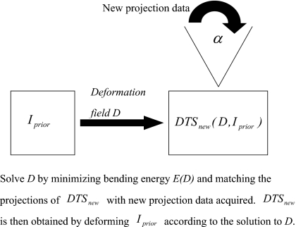
where P* is the Hermitian of the projection matrix P. The starting point of the deformation field is set to be zero and the initial value of the relative weight μ is set to be 1.0×10⁻⁷. After every 100 iterations, the relative weight μ is increased by a factor of 10 and the deformation field solved is used as the starting point of the next 100 iterations. A total of ∼500 iterations are used in the optimization. After the deformation field D is solved, the new on-board DTS image DTSnew is obtained by deforming the prior image Iprior based on Eq. 2. The diagram of this new DTS reconstruction method is shown in Fig. 1.
Figure 1.
Diagram of the new DTS reconstruction method.
Evaluation methods
The accuracy of this novel DTS reconstruction method was quantitatively evaluated by calculating the errors of both organ volume and pixel values reconstructed. The organ volume and pixel values in the new CBCT image CBCTnew were used as the truth. The relative error of the organ volume in the new DTS image DTSnew or the prior image Iprior was calculated as follows:
| (9) |
where V was the organ volume contoured in the DTSnew or Iprior image, and V0 was the organ volume contoured in the CBCTnew image. The error of the pixel values reconstructed was estimated by the reconstructed pixel signal-to-noise ratio (PSNR), which is defined as follows:
| (10) |
where X is the CBCTnew image, and Z is the DTSnew or Iprior image. The numerator describes the signal strength of the new CBCT image and the denominator represents the pixel value reconstruction error.
This DTS reconstruction algorithm was tested using a MATLAB Shepp–Logan phantom, liver and head-and-neck patient data. The image size in all the tests was set to be 256*256. Projections simulated around every 0.5° over 60°–90° scan angles from the new CBCT image CBCTnew were used for DTS reconstruction.
RESULTS
Shepp–Logan phantom
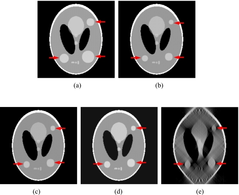
In the Shepp–Logan phantom test, three tumors of different sizes were simulated at different locations in the prior CBCT image CBCTprior, and they were simulated to experience tumor shrinkage in the new CBCT image CBCTnew, as shown in Figs. 2a, 2b. Prior based new DTS images DTSnew reconstructed from 60° and 90° projections are shown in Figs. 2c, 2d, respectively. The FBP based DTS image reconstructed from 90° projections is shown in Fig. 2e for comparison. The reconstructed PSNR for prior based 60° and 90° DTSnew images and the CBCTprior image are shown in Table 1. The deformation field solved using 90° projections is overlaid onto the prior CBCT image in Fig. 3.
Figure 2.
DTS reconstruction of Shepp–Logan phantom using prior based and FBP based methods with 60°–90° scan angles. (The three tumors simulated are indicated by the arrows.) (a) The prior CBCT image CBCTprior, (b) the new CBCT image CBCTnew, (c) prior based 60° DTSnew, (d) prior based 90° DTSnew, (e) FBP based 90° DTSnew.
Table 1.
Reconstructed PSNR for the prior based DTS images and the prior CBCT image in the Shepp–Logan phantom study.
| Prior based 90° DTSnew | Prior based 60° DTSnew | Prior CBCT image CBCTprior | |
|---|---|---|---|
| Reconstructed PSNR (dB) | 35.7 | 34.3 | 18.3 |
Figure 3.
Deformation field (indicated by arrows) solved by the new reconstruction method overlaid onto the prior CBCT image in the Shepp–Logan phantom study. (90° scan angle was used).
Liver patient data
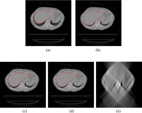
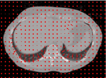
In the liver patient test, the 4D CT images of a liver patient at the exhale and inhale phases were used to simulate two extreme cases for soft tissue deformation in prior CBCT and new CBCT images, as shown in Figs. 4a, 4b. Prior based new DTS images DTSnew reconstructed from 60° and 90° projections are shown in Figs. 4c, 4d, respectively. The FBP based DTS image reconstructed from 90° projections is shown in Fig. 4e for comparison. The deformation field solved by the new method using 90° projections is overlaid onto the prior CBCT image in Fig. 5. To evaluate the organ volume reconstruction error, the liver was contoured in CBCT and DTS images (as shown in Fig. 4). The relative error of the liver volume reconstructed is calculated according to Eq. 9, and the error of the pixel values reconstructed is evaluated by PSNR as defined in Eq. 10. The results are shown in Table 2.
Figure 4.
DTS reconstruction of liver patient data using prior based and FBP based methods with 60°–90° scan angles. (The contours of the liver are shown in the CBCT and prior based DTS images.) (a) The prior CBCT image CBCTprior, (b) the new CBCT image CBCTnew, (c) prior based 60° DTSnew, (d) prior based 90° DTSnew, (e) FBP based 90° DTSnew.
Figure 5.
Deformation field (indicated by arrows) solved by the new reconstruction method overlaid onto the prior CBCT image in the liver patient study. (90° scan angle was used).
Table 2.
The relative error of the liver volume and the reconstructed PSNR for the prior based DTS images and the prior CBCT image in the liver patient study.
| Prior based 90° DTSnew | Prior based 60° DTSnew | Prior CBCT image CBCTprior | |
|---|---|---|---|
| Relative error of the liver volume (%) | 2.3 | 3.4 | 16.2 |
| Reconstructed PSNR (dB) | 28.8 | 23.5 | 15.4 |
Head-and-neck patient data
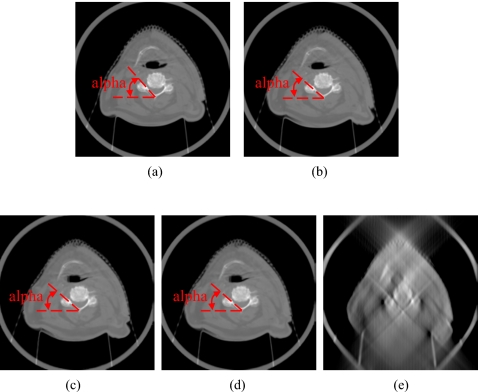
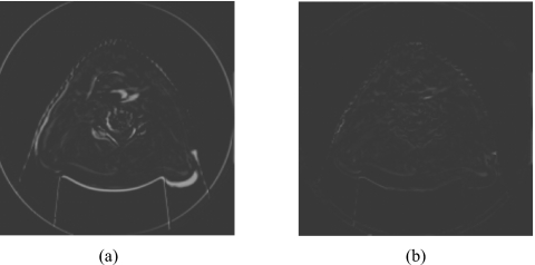
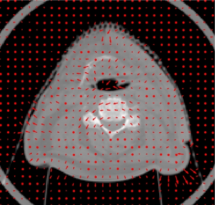
In the head-and-neck patient test, different days’ CBCT images of a head-and-neck patient were used as prior CBCT and new CBCT images, as shown in Figs. 6a, 6b. Prior based new DTS images DTSnew reconstructed from 60° and 90° projections are shown in Figs. 6c, 6d, respectively. The FBP based DTS image reconstructed from 90° projections is shown in Fig. 6e for comparison. The angulations of the bony structures in CBCT and DTS images were evaluated by calculating the angle alpha between the neck bone and the horizontal line, as shown in Fig. 6. Results showed that the bony structure in the new CBCT image has 8.1° counterclockwise rotation relative to the bony structure in the prior CBCT image. In prior based 60° and 90° DTSnew images, this rotation has been accurately reconstructed with 0.0° error. The difference image between CBCTnew and CBCTprior and the difference image between CBCTnew and prior based 60° DTSnew are shown in Figs. 7a, 7b, respectively. The deformation field solved using 90° projections is overlaid onto the prior CBCT image in Fig. 8. The deformation field also shows a counterclockwise rotation of the bony structure in the prior CBCT image. The reconstructed PSNR for prior based 60° and 90° DTSnew images and the CBCTprior image are shown in Table 3. The prior based 60° and 90° DTSnew images have much higher PSNR than the CBCTprior image, which suggests that the DTSnew image is not retaining much of the incorrect anatomical information in the CBCTprior image.
Figure 6.
DTS reconstruction of head-and-neck patient data using prior based and FBP based methods with 60°–90° scan angles. The angulations of the bony structures in CBCT and DTS images were evaluated by calculating the angle alpha between the neck bone and the horizontal line. (a) The prior CBCT image CBCTprior, (b) the new CBCT image CBCTnew, (c) prior based 60° DTSnew, (d) prior based 90° DTSnew, (e) FBP based 90° DTSnew.
Figure 7.
Difference images in the head-and-neck patient study. (a) The difference image between the new CBCT image CBCTnew and the prior CBCT image CBCTprior. (b) The difference image between the new CBCT image CBCTnew and the prior based 60° DTSnew image.
Figure 8.
Deformation field (indicated by arrows) solved by the new reconstruction method overlaid onto the prior CBCT image in the head-and-neck patient study. (90° scan angle was used).
Table 3.
Reconstructed PSNR for the prior based DTS images and the prior CBCT image in the head-and-neck patient study.
| Prior based 90° DTSnew | Prior based 60° DTSnew | Prior CBCT image CBCTprior | |
|---|---|---|---|
| Reconstructed PSNR (dB) | 25.1 | 24.2 | 12.5 |
DISCUSSION
Results show that this new DTS reconstruction method can obtain volumetric information about both soft tissue deformation and rigid body misalignment of bony structures using 60° projections, which are only 1∕6 of the projections acquired in a full CBCT scan. This implies a substantial reduction of the imaging dose and time for daily image guidance in the patient treatment. The deformation field solved during the reconstruction can be used as deformable registration results for tumor localization and dose tracking. Potentially, this method can also be applied for 4D CT, 4D CBCT, and 4D DTS image reconstruction when patients’ prior images are available.
To our knowledge, this is the first time deformable registration has been combined with limited angle image reconstruction. Under this scheme, a series of other DTS reconstruction methods can be developed by introducing other deformation models into reconstruction, such as contour based and control point based deformation models. These models can further reduce the degrees of freedom in the reconstruction and therefore can potentially further reduce the scan angle and the number of projections needed to obtain the volumetric information.
Our next step is to implement this reconstruction algorithm in 3D and make it available for clinical use. The major challenge in its clinical implementation is to improve the speed of the 3D reconstruction algorithm to make the total reconstruction time within the clinical time constraint. This goal can be achieved by using hardware acceleration,11, 31 parallel computing and, algorithm optimization.
CONCLUSION
We developed a novel DTS reconstruction method to reconstruct DTS images using a deformation field map. Volumetric information was optimally estimated using projections within a 60° scan angle. Preliminary validation of the algorithm showed that it is both technically and clinically feasible for image guidance in radiation therapy.
ACKNOWLEDGMENTS
This work was partially supported by the National Institutes of Health Grant No. R21-CA128368, and research grants from Varian Medical Systems (Palo Alto, CA) and GE Healthcare (Waukesha, WI).
References
- Jaffray D. A. and Siewerdsen J. H., “Cone-beam computed tomography with a flat-panel imager: Initial performance characterization,” Med. Phys. 10.1118/1.599009 27, 1311–1323 (2000). [DOI] [PubMed] [Google Scholar]
- Jaffray D. A., Siewerdsen J. H., Wong J. W., and Martinez A. A., “Flat-panel cone-beam computed tomography for image-guided radiation therapy,” Int. J. Radiat. Oncol., Biol., Phys. 10.1016/S0360-3016(02)02884-5 53, 1337–1349 (2002). [DOI] [PubMed] [Google Scholar]
- Letourneau D., Wong J. W., Oldham M., Gulam M., Watt L., Jaffray D. A., Siewerdsen J. H., and Martinez A. A., “Cone-beam-CT guided radiation therapy: Technical implementation,” Radiother. Oncol. 10.1016/j.radonc.2005.03.001 75, 279–286 (2005). [DOI] [PubMed] [Google Scholar]
- Oldham M., Letourneau D., Watt L., Hugo G., Yan D., Lockman D., Kim L., Chen P., Martinez A. A., and Wong J. W., “Cone-beam-CT guided radiation therapy: A model for on-line application,” Radiother. Oncol. 10.1016/j.radonc.2005.03.026 75, 271–278 (2005). [DOI] [PubMed] [Google Scholar]
- Islam M. K., Purdie T. G., Norrlinger B. D., Alasti H., Moseley D. J., Sharpe M. B., Siewerdsen J. H., and Jaffray D. A., “Patient dose from kilovoltage cone beam computed tomography imaging in radiation therapy,” Med. Phys. 10.1118/1.2198169 33, 1573–1582 (2006). [DOI] [PubMed] [Google Scholar]
- J. T.DobbinsIII and Godfrey D. J., “Digital x-ray tomosynthesis: Current state of the art and clinical potential,” Phys. Med. Biol. 10.1088/0031-9155/48/19/R01 48, R65–106 (2003). [DOI] [PubMed] [Google Scholar]
- Godfrey D. J., Yin F. F., Oldham M., Yoo S., and Willett C., “Digital tomosynthesis with an on-board kilovoltage imaging device,” Int. J. Radiat. Oncol., Biol., Phys. 10.1016/j.ijrobp.2006.01.025 65, 8–15 (2006). [DOI] [PubMed] [Google Scholar]
- Godfrey D. J., Yin F. F., Wang Z., Yoo S., Oldham M., and Willett C., “Rapid low-dose 3D image-guided treatment verification of sites prone to respiratory motion using breath-hold on-board digital tomosynthesis (DTS),” Med. Phys. 33, 2268 (2006). [Google Scholar]
- Ren L., Godfrey D. J., Yan H., Wu Q. J., and Yin F. F., “Automatic registration between reference and on-board digital tomosynthesis images for positioning verification,” Med. Phys. 10.1118/1.2831903 35, 664–672 (2008). [DOI] [PubMed] [Google Scholar]
- Godfrey D. J., Ren L., Yan H., Wu Q. J., Yoo S., Oldham M., and Yin F. F., “Evaluation of three types of reference image data for external beam radiotherapy target localization using digital tomosynthesis (DTS),” Med. Phys. 10.1118/1.2756941 34, 3374–3384 (2007). [DOI] [PubMed] [Google Scholar]
- Yan H., Ren L., Godfrey D. J., and Yin F. F., “Accelerating reconstruction of reference digital tomosynthesis using graphics hardware,” Med. Phys. 10.1118/1.2779945 34, 3768–3776 (2007). [DOI] [PubMed] [Google Scholar]
- Wu Q. J., Godfrey D. J., Wang Z., Zhang J., Zhou S., Yoo S., Brizel D. M., and Yin F. F., “On-board patient positioning for head-and-neck IMRT: Comparing digital tomosynthesis to kilovoltage radiography and cone-beam computed tomography,” Int. J. Radiat. Oncol., Biol., Phys. 10.1016/j.ijrobp.2007.05.045 69, 598–606 (2007). [DOI] [PubMed] [Google Scholar]
- Candes E. J., Romberg J., and Tao T., “Robust uncertainty principles: Exact signal reconstruction from highly incomplete frequency information,” IEEE Trans. Inf. Theory 10.1109/TIT.2005.862083 52, 489–509 (2006). [DOI] [Google Scholar]
- Donoho D. L., “Compressed sensing,” IEEE Trans. Inf. Theory 10.1109/TIT.2006.871582 52, 1289–1306 (2006). [DOI] [Google Scholar]
- Chen G., Tang J., and Leng S., “Prior image constrained compressed sensing (PICCS): A method to accurately reconstruct dynamic CT images from highly undersampled projection data sets,” Med. Phys. 10.1118/1.2836423 35, 660–663 (2008). [DOI] [PMC free article] [PubMed] [Google Scholar]
- Velikina J., Leng S., and Chen G., “Limited view angle tomographic image reconstruction via total variation minimization,” Proc. SPIE 6510, 651020 (2007). [Google Scholar]
- Sidky E. Y., Kao C. M., and Pan X., “Accurate image reconstruction from few-views and limited-angle data in divergent-beam CT,” J. X-Ray Sci. Technol. 14, 119–139 (2006). [Google Scholar]
- Song J., Liu Q. H., Johnson G. A., and Badea C. T., “Sparseness prior based iterative image reconstruction for retrospectively gated cardiac micro-CT,” Med. Phys. 10.1118/1.2795830 34, 4476–4482 (2007). [DOI] [PMC free article] [PubMed] [Google Scholar]
- Delaney A. H. and Bresler Y., “Efficient edge-preserving regularization for limited-angle tomography,” IEEE International Conference on Image Processing (ICIP), Vol. 3, 176–179 (1995).
- Persson M., Bone D., and Elmqvist H., “Total variation norm for three dimensional iterative reconstruction in limited view angle tomography,” Phys. Med. Biol. 10.1088/0031-9155/46/3/318 46, 853–866 (2001). [DOI] [PubMed] [Google Scholar]
- Herman G., Image Reconstruction from Projections (Academic, Orlando, 1980). [Google Scholar]
- Li T., Schreibmann E., Yang Y., and Xing L., “Motion correction for improved target localization with on-board cone-beam computed tomography,” Phys. Med. Biol. 10.1088/0031-9155/51/2/005 51, 253–267 (2006). [DOI] [PubMed] [Google Scholar]
- Li T., Koong A., and Xing L., “Enhanced 4D cone-beam CT with inter-phase motion model,” Med. Phys. 10.1118/1.2767144 34, 3688–3695 (2007). [DOI] [PubMed] [Google Scholar]
- Badea C. T., Schreibmann E., and Fox T., “A registration based approach for 4D cardiac micro-CT using combined prospective and retrospective gating,” Med. Phys. 10.1118/1.2868778 35, 1170–1179 (2008). [DOI] [PMC free article] [PubMed] [Google Scholar]
- Wierzbicki M., Guiraudon G. M., Jones D. L., and Peters T., “Dose reduction for cardiac CT using a registration-based approach,” Med. Phys. 10.1118/1.2731030 34, 1884–1895 (2007). [DOI] [PubMed] [Google Scholar]
- Zeng R., Fessler J. A., and Balter J. M., “Respiratory motion estimation from slowly rotating x-ray projections: Theory and simulation,” Med. Phys. 10.1118/1.1879132 32, 984–991 (2005). [DOI] [PubMed] [Google Scholar]
- Ehrhardt J., Werner R., Saring D., Frenzel T., Lu W., Low D., and Handels H., “An optical flow based method for improved reconstruction of 4D CT data sets acquired during free breathing,” Med. Phys. 10.1118/1.2431245 34, 711–721 (2007). [DOI] [PubMed] [Google Scholar]
- Bookstein F. L., “Principal warps: Thin-plate splines and the decomposition of deformations,” IEEE Trans. Pattern Anal. Mach. Intell. 10.1109/34.24792 11, 567–585 (1989). [DOI] [Google Scholar]
- Fletcher R. and Reeves C. M., “Function minimization by conjugate gradients,” Comput. J. 10.1093/comjnl/7.2.149 7, 149–154 (1964). [DOI] [Google Scholar]
- Lustig M., Donoho D., and Pauly J., “Sparse MRI: The application of compressed sensing for rapid MR imaging,” Magn. Reson. Med. 10.1002/mrm.21391 58, 1182–1195 (2007). [DOI] [PubMed] [Google Scholar]
- Yan H., Godfrey D. J., and Yin F. F., “Fast reconstruction of digital tomosynthesis using on-board images,” Med. Phys. 10.1118/1.2896077 35, 2162–2169 (2008). [DOI] [PMC free article] [PubMed] [Google Scholar]


