Abstract
Digital tomosynthesis (DTS) is a method to reconstruct pseudo three-dimensional (3D) volume images from two-dimensional x-ray projections acquired over limited scan angles. Compared with cone-beam computed tomography, which is frequently used for 3D image guided radiation therapy, DTS requires less imaging time and dose. Successful implementation of DTS for fast target localization requires the reconstruction process to be accomplished within tight clinical time constraints (usually within 2 min). To achieve this goal, substantial improvement of reconstruction efficiency is necessary. In this study, a reconstruction process based upon the algorithm proposed by Feldkamp, Davis, and Kress was implemented on graphics hardware for the purpose of acceleration. The performance of the novel reconstruction implementation was tested for phantom and real patient cases. The efficiency of DTS reconstruction was improved by a factor of 13 on average, without compromising image quality. With acceleration of the reconstruction algorithm, the whole DTS generation process including data preprocessing, reconstruction, and DICOM conversion is accomplished within 1.5 min, which ultimately meets clinical requirement for on-line target localization.
Keywords: digital tomosynthesis (DTS), cone-beam computed tomography (CBCT), image guided radiation therapy, digitally reconstructed radiograph (DRR)
INTRODUCTION
With the introduction of the on-board imager (OBI), it is possible to monitor the position of planning targets for daily treatment verification based on three-dimensional (3D) cone-beam computed tomography (CBCT) image data.1 To reconstruct a set of CBCT images, it typically requires approximate 700 projection images to be acquired over a full gantry rotation covering 0°−360°. The acquisition time for one CBCT imaging session takes about 1 min, and the absorb dose of such acquisition on patient skin was around 3–6 cGy.2, 3, 4 If the patient imaging is performed on a daily basis, the accumulated imaging time and dose over multiple fractions is considerable. Thus, patients may benefit if 3D images can be reconstructed from projections acquired in a limited scan angle (<60°) without substantial loss of key anatomical information.
In clinical practice, a small region of interest surrounding the treatment site or fiducial markers is often used for image registration. It might be feasible to only reconstruct the 3D image around treatment isocenter with fewer projections. Recently, a technique with such potential, digital tomosynthesis, was investigated by our group for clinical target localization purposes.5, 6, 7 This technique reconstructs partial∕pseudo-3D images from projections acquired over a limited scan angle, typically 40°−60°. The reconstructed images present high spatial resolution of anatomical structures in any plane whose orientation is perpendicular to the middle of the digital tomosynthesis (DTS) scan angle. As a trade-off, anatomical structures located outside of the focal plane are gradually blurred as distance increases due to missing information that results from the use of a limited scan angle.8 Due to the limited scan angle of DTS, and the resulting sacrifice of 3D resolution, patient imaging time and dose can be greatly shortened by a factor of 3−6. The rapid acquisition of DTS is particularly beneficial for the imaging of targets affected by organ motion, as it reduces the chance that target motion will occur during image guidance.
Currently, there is no commercial system or hardware available for DTS reconstruction for image guided radiation therapy. The conventional software-based reconstruction techniques are far too time consuming for clinical use. The current application implemented on a conventional central processing unit (CPU) usually takes about 10–15 min to reconstruct a set of DTS consisting of 200 slices from projection images using the popular Feldkamp, Davis, and Kress (FDK) algorithm.5, 6 Considering that an additional 30–60 min is needed to reconstruct digitally reconstructed radiographs (DRRs) from a planning CT, for use in generating a reference DTS set, the total time required to generate a set of reference DTS from DRRs would be 40–75 min. In our previous study, DRR reconstruction was implemented on common graphics hardware, and the reconstruction performance was improved by a factor of 67. Thus, a set of DRR images can be reconstructed within 1 min.7 However, DTS reconstruction is still hampered by low reconstruction efficiency since 10–15 min is considered unacceptable for on-line use.
Commercial tomography reconstruction systems built on customized hardware have demonstrated the capacity to quickly reconstruct 3D images for on-line clinical applications. However, this type of customized hardware is relatively expensive for research purposes. In addition, the hardware is usually designed using a fixed architecture for a given application and orients only to those professional users in hardware design and development. Such hardware does not have the flexibility to be adjusted to meet specific requirements of custom applications. Recently, high-end personal computer graphics boards emerged to meet the fast-growing demands of the computer game industry. Modern graphics processing units (GPUs) are very efficient at manipulating and displaying computer graphics, and their highly parallel structure makes them more effective than general-purpose CPUs for a range of complex algorithms. Previous studies were conducted on accelerating reconstruction of CT and CBCT on general purpose GPU, showing that significant acceleration can be achieved without compromising image quality.9, 10
A variety of reconstruction algorithms have been developed for reconstructing DTS images from limited scan angles.11, 12, 13, 14, 15, 16, 17 Among them, the filtered backprojection algorithm, especially the one proposed by Feldkamp, Davis, and Kress, is almost universally practiced and is perhaps the most efficient for DTS reconstruction due to its simplicity.18, 19 The major operation of backprojection consists of millions of pixel∕voxel interpolations which are highly time consuming. It is ideal to implement them on graphics hardware which is more efficient for volume rendering. In this study a DTS reconstruction based on the FDK algorithm was implemented on graphics hardware. DTS images were reconstructed using the acceleration algorithm and compared with those reconstructed using the software version of this algorithm. The reconstruction program was written in graphics industry standard library—OpenGL. The performance of this acceleration method was evaluated using a chest phantom and real patient data.
MATERIALS AND METHODS
Graphics hardware fundamentals
The processing pipeline of a GPU consists of three steps as illustrated in Fig. 1. (1) Geometry processing: a 3D model initially defined by a set of vertices is decomposed into several geometrical primitives, such as planar polygons. (2) Rasterization: these geometrical primitives are converted to a two-dimensional (2D) array of fragments. (3) Per-fragment operations: a series of operations in simulating special effects such as light and texture are performed on these fragments, and the final fragments after these processes are drawn on a frame buffer for display.7, 20, 21 To provide a convenient way of programming on graphics hardware, an application programming interface (API) is needed to act as an interface between the high-level programming language and the specific device driver for the identified hardware. In this study, OpenGL was selected which is the most widely used API in the graphics industry.22, 23
Figure 1.
The standard graphics pipeline for display traversal on a GPU.
Principle of DTS reconstruction based on the FDK algorithm
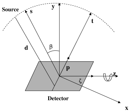
The term tomosynthesis commonly refers to the generation of a set of slice images from the summation of a set of shifted projection images acquired at different tube orientations.8 It is similar to 3D computed tomography algorithms which reconstruct volumetric slices from projection images but uses limited scan angles. The geometry parameters for DTS reconstruction based on the FDK algorithm are illustrated in Fig. 2, and the corresponding reconstruction formulation is as follows:3
| (1) |
where f(x,z∕y) is the reconstructed plane (x,z) through a given depth y, β refers to the scan angle and is confined to a limited range |βmax−βmin|≪2π, d is the source-to-isocenter distance, s=−x sin β+y cos β is the distance of a voxel from the detector plane, p and ζ are the detector axes perpendicular and parallel to the axis of rotation, respectively, P(⋅) is the projection data, and H(⋅) denotes a one dimensional ramp filter with a Hamming window, applied alongp, with t=−x cos β+y sin β. Concisely, Eq. 1 can be expressed as follows:24
| (2) |
where H is the filtering operator corresponding to the inner integral in Eq. 1, B is the backprojection operator corresponding to the outer integral in Eq. 1, V is the reconstructed volume, S is the number of projections in the set, and Pβ is the projection image taken at scan angle β. The filtering operator F can be quickly accomplished by fast Fourier transform, but backprojection operation is the most time consuming if it runs on a general purpose CPU. It should note that the reconstruction algorithm described here is just plain filtered backprojection, technically not the FDK algorithm. The FDK algorithm includes fan-beam and cone-beam weights for the projection data. In our implementation, the cone-beam weights were turned off as it did not seem to improve the reconstructions noticeably.
Figure 2.
Digital tomosynthesis acquisition and reconstruction geometry.
Hardware implementation of the FDK algorithm
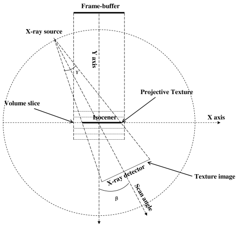
To implement the backprojection operation using a GPU, the 2D projection image acquired on detector plane is to be projected back to the 3D volume located at isocenter along the cone beam rays. This is the reverse process of projection in forward direction. The backprojecting process using texture mapping of graphics hardware is illustrated in Fig. 3, where the 2D projection image is stored in a texture of GPU memory and associated with the volume slice by the predetermined transforms. Texture is simply a rectangular array of data such as gray values. The individual value of a texture array is often called texel. The volume slice is first drawn at the location in user coordinate system as indicated by the dot line parallel to the x axis. Then, it is converted to geometrical primitives via geometric processing, then these primitives are rasterized to 2D fragments. To correctly backproject a texture (projection image) onto a volume slice along a ray direction, a technique called projective texture mapping was employed, as described by Segal et al.25 This procedure is analogous to the process of slide projection, in which the texture image is a slide that is projected with a cone-beam “light” source onto a slide screen (the volume slice), and finally the projected slide is photographed by a parallel-beam camera as the image viewed from the frame buffer in the orthogonal projection, as shown in Fig. 3. Prior to the operation applied to fragments, the texture image is converted to a projective texture image via a precalculated transform. During the per-fragment operation, the projective texture is mapped onto these fragments as a solid line, indicated by the arrow in Fig. 3. Finally, the texture-mapped fragments are drawn on the frame buffer. This backprojection process is repeated for all projections. The image previously drawn on the frame buffer is blended with the new one until all projections are accumulated on the frame buffer to form the final DTS image. This image can be readout from the frame buffer and saved to a file. To generate the next DTS slice, the current content of the frame buffer is cleared, and the same process is repeated but with a different DTS slice depth.
Figure 3.
Illustration of reconstructing DTS from OBI projection using a projective texture mapping technique.
Virtual extension of texture memory precision
Due to the limitation of texture precision (8 bits∕texel) on our GPU memory, the original projection data must be downsampled from 16 to 8 bits for storage. It is problematic since this processing may cause loss of image detail. To resolve this issue, a scheme which virtually extends the precision of texture memory was adopted, similar to the one we reported previously for the acceleration of DRR reconstruction.6 Unlike the previous application, the projection images, rather than the CT images, are stored in the texture memory. With this extension strategy, a DTS image with a depth of 16 bits∕pixel can be generated from projection images with a depth of 12 bits∕texel (even higher depending on the application requirement) without any loss of image detail.
Image analysis
The difference image was calculated between the DTS image reconstructed based on software and hardware methods to check whether there are visible residual anatomical structures existing. The correlation between the two techniques was quantified by correlation coefficient. The correlation coefficient between two images with the same size was calculated by using MATLAB function—CORR2 (The MathWorks, Inc., Natick, MA). The two reconstruction implementations were also compared using a contrast-to-noise ratio (CNR) figure of merit, computed in two homogenous regions of interest (ROIs) in the reconstructed images. The formula is
| (3) |
where A and B represent the regions of interest labeled in a single image. The relative difference between CNRs of two DTS images are then calculated as follows:
| (4) |
Clinical test
To test the hardware DTS reconstruction method, we installed the system in a real clinical environment and evaluated DTS registration for five patients undergoing spinal radiosurgery. Each patient was aligned for treatment using on-board cone-beam CT image data. As the projection images for the cone-beam CT were acquired by the on-board imaging system, they were immediately transferred to the DTS workstation where the hardware-based reconstruction program was installed. There, the projection images were first decompressed and saved in a specific format required by the reconstruction program. Then, DTS slices were reconstructed by the program and converted to DICOM format. Prior to the on-board imaging session, the set of reference DTS images was calculated from a planning CT. Both sets of on-board DTS and reference DTS were loaded into the registration software, in which the offset of the planning target was identified by physician using the DTS image data. Simultaneously, the offset of the planning target was identified by another physician using CBCT and CT image data. Finally, the difference between the two offsets was evaluated.
RESULTS
In this study, all programs were written using the widely adopted OpenGL API and can be easily implemented on a personal computer equipped with general purpose graphics hardware. Phantom and patient projection data were acquired with full rotation of gantry (covering scan angles 0°−360° with 0.54° intervals) using an OBI system (Varian Medical Systems, Inc., Palo Alto, CA) yielding a set of 670 cone-beam projections with image size 1024×768. These projections were subsequently downsampled to 512×384. Subsets of the projections over limited scan angles (60 deg) were used for reconstructing sets of DTS image consisting of 63, 127, 255, 383, and 511 slices. The projection image with 16 bits precision was compressed to 12 bits to alleviate the limitation of GPU memory size. Due to processing of the virtual memory extension, there is minor round-off error introduced during bit partition and reassembly, which may cause the value range of resulting DTS images using the acceleration algorithm to slightly differ from that of DTS images generated based on conventional software algorithm.
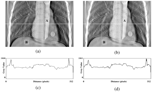
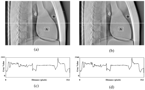
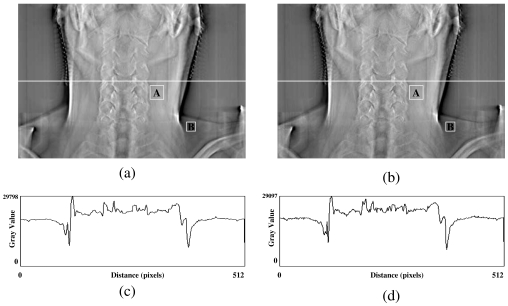
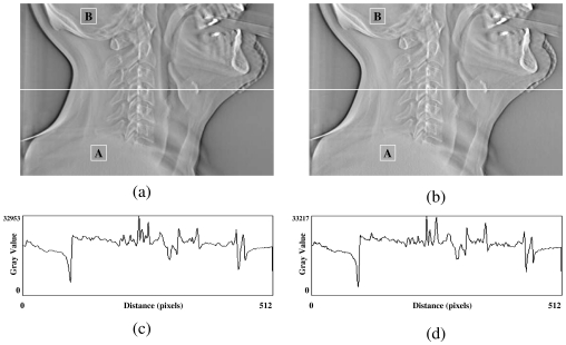
In the first test, a DTS image was reconstructed based on on-board projection images acquired from a chest phantom. Figures 4a, 4b show the central slices (i.e., isocentric plane) of the DTS reconstructed in the coronal view using the software and hardware methods from a phantom (chest case). The corresponding central profiles are shown in Figs. 4c, 4d. The central slices for sagittal views are shown in Figs. 5a, 5b for both methods, and their corresponding central profiles are shown in Figs. 5c, 5d. The mean values ± standard deviations of their difference images shown in Figs. 45 are equal to zero. The correlation coefficients are both 100% between DTS images in two sets as shown in Figs. 45. In the second test, a set of DTS images was reconstructed based on on-board projection images acquired from a patient undergoing head-and-neck radiation therapy. Figures 6a, 6b show the central slices (i.e., isocentric plane) of the DTS images reconstructed in the coronal view using the software and hardware methods. The corresponding central profiles (as indicated by the white line) are shown in Figs. 6c, 6d. The central slices for the sagittal views are shown in Figs. 7a, 7b for both methods, and their central profiles are shown in Figs. 7c, 7d. The difference between the two DTS images in Figs. 67 show that there is no residual anatomical detail. The mean values ± standard deviations of the difference images are equal to zero. The correlation coefficients are 100% between the two DTS images in two sets as shown in Figs. 67. Two ROIs as shown in Figs. 4567 with the same size and location were selected. The CNRs for those subimages were calculated based on Eq. 3, and the relative CNR difference between two images in a figure was calculated based on Eq. 4 and all results were shown in Table 1.
Figure 4.
Central slices of DTS reconstructed in AP view using the software (a) and the hardware (b) methods for a phantom (chest case). (c) and (d) are central profiles for (a) and (b), respectively.
Figure 5.
Central slices of DTS reconstructed in lateral view using the software (a) and the hardware (b) methods for a phantom (chest case). (c) and (d) are central profiles for (a) and (b), respectively.
Figure 6.
Central slices of DTS reconstructed in AP view using the software (a) and the hardware (b) methods for a real patient (head and neck case). (c) and (d) are central profiles for (a) and (b), respectively.
Figure 7.
Central slices of DTS reconstructed in lateral view using the software (a) and the hardware (b) methods for a real patient (head and neck case). (c) and (d) are central profiles for (a) and (b), respectively.
Table 1.
The comparison of contrast-to-noise ratio (CNR) between DTS images reconstructed by hardware and software methods.
The time efficiency of software and hardware reconstructions with respect to the different number of projection images used and volume slices reconstructed are comparatively summarized in Table 2. As the number of volume slices increases, the gap between reconstruction times provided by both methods is enlarged. For example, generating a set of DTS images with 500 slices based on 200 projection images, the time required using the software method is 33 min while the time is only 2.5 min when using the hardware method. It also shows that the increase of reconstruction time is linearly correlated with the increase of the number of DTS slices or on-board projection images. On average, the time cost for reconstructing a single slice of DTS from 200 projection images is 19.5 ms using the software method and 1.5 ms using the hardware method. Compared with the reconstruction performance of the software method, the hardware method accelerated DTS reconstruction by a factor of 13. For clinical use, a set of DTS images consisting of 255 slices is generally enough for target localization purposes. This reconstruction can be accomplished within 40 s using the current hardware method. In the clinical test, the offsets identified by DTS-based and CBCT-based image registration procedures were compared and good consistency between them was achieved. The maximal discrepancy across all five patients was less than 1 mm. The whole procedure including preprocessing, image reconstruction, and DICOM conversion takes approximately 1.5–2.0 min to complete, and it is reasonable to expect that this will meet the time constraint required for on-line target verification.
Table 2.
The comparison of time spent on DTS reconstruction by hardware and software methods. Ns: The number of DTS slices reconstructed. Np: The number of projection images required for DTS reconstruction. T1: The time usage of software method. T2: The time usage of hardware method.
| Time (minutes) | ||||||||||
|---|---|---|---|---|---|---|---|---|---|---|
| Np | Ns=63 | Ns=127 | Ns=255 | Ns=383 | Ns=511 | |||||
| T1 | T2 | T1 | T2 | T1 | T2 | T1 | T2 | T1 | T2 | |
| 40 | 0.85 | 0.07 | 1.83 | 0.13 | 3.17 | 0.25 | 5.18 | 0.40 | 6.83 | 0.52 |
| 80 | 1.63 | 0.12 | 3.33 | 0.25 | 6.18 | 0.48 | 10.12 | 0.77 | 13.30 | 0.97 |
| 120 | 2.45 | 0.22 | 5.25 | 0.37 | 9.28 | 0.67 | 15.02 | 1.13 | 19.80 | 1.50 |
| 160 | 3.30 | 0.27 | 7.00 | 0.48 | 12.40 | 0.97 | 20.18 | 1.52 | 26.50 | 1.98 |
| 200 | 4.13 | 0.35 | 8.73 | 0.63 | 15.17 | 1.15 | 24.98 | 1.97 | 33.15 | 2.52 |
DISCUSSION
The feasibility of applying new generation graphics hardware for accelerating DTS reconstruction was investigated in this study. Compared with the conventional software based reconstruction method, the hardware-based method demonstrates a substantial improvement in reconstruction efficiency without sacrificing image quality. The visibility of anatomic structures in ten head and neck cases were conducted by several physicians, there is no major difference found between the DTS images reconstructed using the hardware method and the software methods based on compressed projection images (12 bits∕pixel). Based on the mean values and correlation coefficients calculated between two sets of images shown in Figs. 4567, it shows that the DTS images reconstructed by hardware and software methods are almost identical. The investigation on CNR of DTS images revealed that the contrast between selected regions of interest in both sets of images is similar. The relative difference is less than 10%. Therefore, the image quality of the hardware-based FDK algorithm is comparable to those of DTS images generated based on the software-based method and should be acceptable for clinical use. The current reconstruction time for producing a set of DTS images consisting of 200 slices is less than 1.0 min, which meets the clinical time constraint required for target localization.
To alleviate the issue of limited resolution of GPU memory, such as texture memory and frame buffer, an extension scheme was adopted which virtually extends the bit depth of GPU memory from 8 to 12 bits. For treatment verification purposes, the DTS image bit depth based on projection images in 12-bit precision is adequate. It is still possible to further extend the resolution of GPU memory if more precise DTS images are required. It should be noted that there is an extra time cost for reading out images from the frame buffer as it is full. If more precise projection texture is required, more bits of color channels of a texel will need to be used for storing pixel values, and less projection textures will be allowed to accumulate on the frame buffer at one time. As a consequence, more frame buffer readout operations will be needed to temporarily save the intermediate image from the frame buffer to CPU memory. Since the frame buffer readout operation also takes time, the more precision is required for the projection texture, the worse the performance of the reconstruction process will be. With the current settings employed in this study, one readout was conducted after 16 textures were drawn and accumulated on the frame buffer to maintain a high-performance reconstruction process.
CONCLUSION
An accelerated FDK algorithm for DTS reconstruction was implemented on graphics hardware and tested with phantom and clinical data. The reduction of reconstruction time was significant compared with the corresponding software implementation. A reconstruction task of typical size for clinical applications was accomplished within 1 min, demonstrating a 13-fold improvement in efficiency. Though the reconstruction time was considerably reduced, the visibility of anatomical structures on DTS was not compromised, and good image quality was maintained. With the acceleration of DTS reconstruction, time spent on the whole process of DTS-based target localization including preprocessing, image reconstruction, and registration would be significantly shortened, making it potentially feasible for on-line clinical practice.
ACKNOWLEDGMENTS
This work was in partially supported by Varian Medical Systems, NIH, and GE. We thank Jacqueline M. Maurer for her extensive editing support.
References
- Oldham M., Létourneau D., Watt L., Hugo G., Yan D., Lockman D., Kim L. H., Chen P. Y., Martinez A., and Wong J. W., “Cone-beam-CT guided radiation therapy: A model for on-line application,” Radiother. Oncol. 10.1016/j.radonc.2005.03.026 75, 271–278 (2005). [DOI] [PubMed] [Google Scholar]
- Yoo S., Kim G. -Y., Hammoud R., Elder E., Pawlicki T., Guan H., Fox T., Luxton G., Yin F., and Munro P., “A quality assurance program for the on-board imager,” Med. Phys. 10.1118/1.2362872 33, 4431–4447 (2006). [DOI] [PubMed] [Google Scholar]
- Li T., Xing L., Munro P., McGuinness C., Chao M., Yang Y., Loo B., and Koong A., “Four-dimensional cone-beam computed tomography using an on-board imager,” Med. Phys. 10.1118/1.2349692 33, 3825–3833 (2006). [DOI] [PubMed] [Google Scholar]
- Wen N., Guan H., Hammoud R., Pradhan D., Nurushev T., Li S., and Movsas B., “Dose delivered from Varian’s CBCT to patients receiving IMRT for prostate cancer,” Phys. Med. Biol. 10.1088/0031-9155/52/8/015 52, 2267–2276 (2007). [DOI] [PubMed] [Google Scholar]
- Godfrey D. J., Yin F., Oldham M., Yoo S., and Willett C., “Digital tomosynthesis with an on-board kilovoltage imaging device,” Int. J. Radiat. Oncol., Biol., Phys. 10.1016/j.ijrobp.2006.01.025 65, 8–15 (2006). [DOI] [PubMed] [Google Scholar]
- Godfrey D. J., Ren L., Yan H., Wu Q., Yoo S., Oldham M., and Yin F., “Evaluation of three types of reference image data for external beam radiotherapy target localization using digital tomosynthesis (DTS),” Med. Phys. 10.1118/1.2756941 34, 3374–3384 (2007). [DOI] [PubMed] [Google Scholar]
- Yan H., Ren L., Godfrey D. J., and Yin F., “Accelerating reconstruction of reference digital tomosynthesis using graphics hardware,” Med. Phys. 10.1118/1.2779945 34, 3768–3776 (2007). [DOI] [PubMed] [Google Scholar]
- J. T.DobbinsIII and Godfrey D. J., “Digital x-ray tomosynthesis: Current state of the art and clinical potential,” Phys. Med. Biol. 10.1088/0031-9155/48/19/R01 48, R65–R106 (2003). [DOI] [PubMed] [Google Scholar]
- Xu F. and Mueller K., “Accelerating popular tomographic reconstruction algorithms on commodity PC graphics hardware,” IEEE Trans. Nucl. Sci. 10.1109/TNS.2005.851398 52, 654–663 (2005). [DOI] [Google Scholar]
- Xu F. and Mueller K., “Real-time 3D computed tomographic reconstruction using commodity graphics hardware,” Phys. Med. Biol. 10.1088/0031-9155/52/12/006 52, 3405–3419 (2007). [DOI] [PubMed] [Google Scholar]
- Grant D. G., “Tomosynthesis: A three-dimensional radiographic imaging technique,” IEEE Trans. Biomed. Eng. 10.1109/TBME.1972.324154 19, 20–28 (1972). [DOI] [PubMed] [Google Scholar]
- Kolitsi Z., Anastassopoulos V., Scodras A., and Pallikarakis N., “A multiple projection method for digital tomosynthesis,” Med. Phys. 10.1118/1.596822 19, 1045–1050 (1992). [DOI] [PubMed] [Google Scholar]
- Lauritsch G. and Harer W. H., “A theoretical framework for filtered backprojection in tomosynthesis,” Proc. SPIE 10.1117/12.310839 3338, 1127–1137 (1998). [DOI] [Google Scholar]
- Colsher J. G., “Iterative three-dimensional image reconstruction from tomographic projections,” Comput. Graph. Image Process. 6, 513–537 (1977). [Google Scholar]
- J. T.DobbinsIII, “Matrix inversion tomosynthesis improvements in longitudinal x-ray slice imaging,” U.S. Patent No. 4,903,204 (1990).
- Godfrey D. J., Warp R. J., and J. T.DobbinsIII, “Optimization of matrix inverse tomosynthesis,” Proc. SPIE 10.1117/12.430908 4320, 696–704 (2001). [DOI] [Google Scholar]
- Godfrey D. J., Rader A., and J. T.DobbinsIII, “Practical strategies for the clinical implementation of matrix inversion tomosynthesis (MITS),” Proc. SPIE 5030, 379–390 (2003). [Google Scholar]
- Feldkamp L. A., Davis L. C., and Kress J. W., “Practical cone beam algorithm,” J. Opt. Soc. Am. 1, 612–619 (1984). [Google Scholar]
- Avinash C. K. and Malcolm S., Principles of Computerized Tomographic Imaging (Society for Industrial and Applied Mathematics, Philadelphia, 2001). [Google Scholar]
- Foley J., Dam A. V., Feiner S., and Hughes J., Computer Graphics: Principles and Practice (Addison-Wesley, New York, 1990). [Google Scholar]
- Watt A., Fundamentals of Three-Dimensional Computer Graphics (Addison-Wesley, Reading, 1989). [Google Scholar]
- Neider J., Davis T., and Woo M., OpenGL Programming Guide (Addison-Wesley, Reading, 1993). [Google Scholar]
- Segal M. and Akeley K., “The OpenGL graphyics system: A specification (Version 2.1),” www.opengl.org (2006).
- Xu F. and Mueller K., “Ultra-fast 3D filtered backprojection on commodity graphics hardware,” IEEE International Symposium on Biomedical Imaging: From Nano to Macro, Arlington, Virginia, 2004. (unpublished).
- Segal M., Korobkin C., Widenfelt R. V., Foran J., and Haeberli P. E., “Fast shadows and lighting effects using texture mapping,” Proc. SIGGRAPH, 1992, Vol. 92, pp. 249–252 (unpublished).


