Abstract
The purpose of this work was to commission a 120 kVp photon beam produced by a micro-computed tomography (microCT) scanner for use in irradiating mice to therapeutic doses. A variable-aperture collimator has been integrated with a microCT scanner to allow the delivery of beams with pseudocircular profiles of arbitrary width between 0.1 and 6.0 cm. The dose rate at the isocenter of the system was measured using ion chamber and gafchromic EBT film as 1.56–2.13 Gy min−1 at the water surface for field diameters between 0.2 and 6.0 cm. The dose rate decreases approximately 10% per every 5 mm depth in water for field diameters between 0.5 and 1.0 cm. The flatness, symmetry and penumbra of the beam are 3.6%, 1.0% and 0.5 mm, respectively. These parameters are sufficient to accurately conform the radiation dose delivered to target organs on mice. The irradiated field size is affected principally by the divergence of the beam. In general, the beam has appropriate dosimetric characteristics to accurately deliver the dose to organs inside the mice’s bodies. Using multiple beams delivered from a variety of angular directions, targets as small as 2 mm may be irradiated while sparing surrounding tissue. This microCT/RT system is a feasible tool to irradiate mice using treatment planning and delivery methods analogous to those applied to humans.
1. Introduction
Small animals are key components of preclinical research. Mice have been employed for many years as models in which cancer biology may be studied and therapies may be developed prior to translation into the clinic. These vertebrate models have served critical roles in improving cancer detection, understanding carcinogenesis and tumor progression, and evaluating therapeutic response. However, while animal models of cancer have advanced tremendously, models of radiotherapy applicable to these subjects have lagged behind their clinical counterparts. In the early 1970s, Hranitzky et al (1973) designed an irradiator exclusively for rodents. Their system consisted of two Cs-137 sources of 2600 Ci separated by 27 cm that were placed in a cylindrical lead shield. The system achieved dose rates of 1.1 Gy min−1 at the intersection of the two sources for field sizes as small as 3 cm in diameter. However, the development of new equipment technology and cancer treatment techniques for humans has limited the relevance of early small animal radiation systems. Currently, standard radiation facilities for humans are equipped with rotating linear accelerators and multi-leaf collimators to deliver intensity-modulated radiotherapy (IMRT). Radiation systems are also equipped to account for inter- and intra-fraction organ motion. To reduce the uncertainty in the dose delivery, treatments are monitored with new techniques (Dawson and Jaffray 2007, Jaffray 2005, Bouchet et al 2001) such as on-board kV-cone beam computed tomography (CBCT) and optical-guided 3D ultrasound techniques, creating a new treatment modality dubbed image-guided radiotherapy (IGRT). Dose shaping and monitoring technology of this type, while commonplace in the clinic, is not to be found in the laboratory for preclinical models.
In order to rectify this situation and implement clinically relevant radiotherapy methods for small animal models of disease, treatment facilities that accommodate the size of these small animals and have dosimetric properties similar to those of radiation systems used to treat tumors in humans must be developed. Several groups are working to integrate radiation treatment planning and 3D conformal radiation therapy systems with multimodality imaging capabilities exclusively for rodents (Stojadinovic et al 2006a, 2006b, 2007, Chow and Leung 2007, Deng et al 2006, Tryggestad et al 2006, Ford et al 2006, Jaffray et al 2006). In addition, other groups are modifying existing radiation systems to conduct partial body irradiation in rats (Khan et al 1998, 2003, DesRosiers et al 2003, Sugiyama et al 2005, Takahashi et al 2002, Swicord et al 1999). Recently, a novel microCT-based IGRT system equipped with a variable-aperture collimator has been proposed (Graves et al 2007a, Zhou et al 2007). This device is able to perform 3D conformal therapy in mice with field sizes as small as 1 mm, making it suitable for irradiation of small targets such as prostate, liver, bladder and lungs in mice. While still in development, this system has the potential to deliver intensity-modulated radiotherapy by varying the field diameter, beam angle, and bed position during the course of radiation delivery.
Commissioning a microCT for mouse irradiation is a challenge due to space restrictions, small field sizes and detector limitations. Thimble ion chambers may be used to measure output but they are limited to field sizes larger than 4 × 4 cm2. The dose rate for radiation fields smaller than 4 cm in diameter should not be measured using an ion chamber due to the partial volume effect in the chamber (Laub and Wong 2003). Radiochromic film has been used previously for dosimetry of small fields (Stojadinovic et al 2005, 2006b, Deng et al 2006). Because of its high spatial resolution in two dimensions, radiochromic film is the most appropriate detector to evaluate dose distribution delivered by pinpoint beams. In addition, no specialized film processing is needed, the film is insensitive to light and it can be cut in any size or shape. Radiochromic film also offers such dosimetric advantages as tissue equivalency. Gafchromic EBT film, for instance, has a weak energy dependence (Butson et al 2006, Fuss et al 2007), low dose rate dependence (Fuss et al 2007) and does not exhibit temporal growth of optical density (Fuss et al 2007, Todorovic et al 2006, Cheung et al 2005). A combination of measurements taken with the ion chamber and gafchromic EBT film may provide practical absolute and relative dosimetry of small animal irradiators operating at kilovoltage energies and small field sizes. The main goal of the current study was to commission a microCT system equipped with a variable-aperture collimator for small animal radiation therapy. Ion chamber and gafchromic film measurements were used to determine the dose rate at the isocenter of the microCT as a function of depth for different field sizes. In addition, we quantified the flatness and symmetry of the x-ray beam and evaluated the spatial and dosimetric accuracy of the dose delivered.
2. Methods and materials
2.1. Output of the microCT/RT system
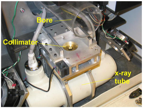
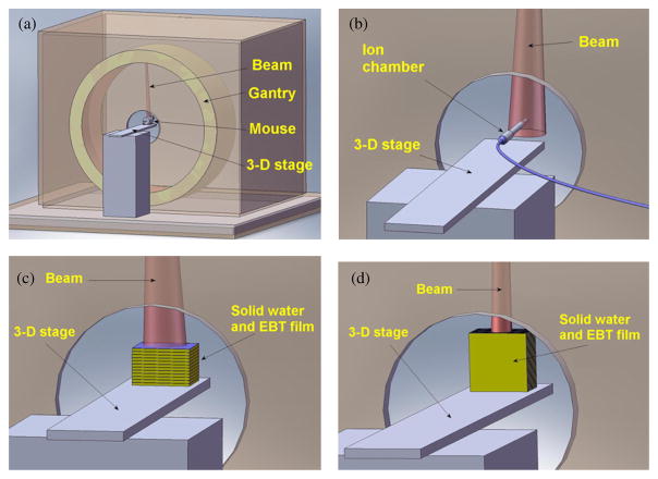
The platform for this work was a GE eXplore RS120 microCT scanner (GE Healthcare, London, Ontario, Canada). The prototype collimator was designed for installation on the gantry of a custom RS120 microCT scanner, manufactured for this project by GE Medical Systems and bearing a higher capacity x-ray tube than the standard RS120 as well as a mounting bar on the gantry between the x-ray tube and subject bore for attachment of the collimator. This prototype microCT scanner became the basis for the current eXplore CT120 scanner, meaning that the development of radiotherapy on the RS120 can easily be translated to current microCT scanners through the addition of collimation and subject positioning equipment. Our scanner was modified, to irradiate mice, by adding a collimation system consisting of two stages each with an adjustable hexagonal iris (see figure 1). The two irises are offset by 30° so that when the openings of the two stages are properly adjusted to the same size, a dodecagonal beam profile is formed. The variable-aperture collimator is capable to limit the beam to fields as small as 1 mm in diameter. This configuration of the radiation system allows us to irradiate mice in style similar to tomotherapy (figure 2(a)). The output of the 120 kVp photon beam provided by the GE microCT was measured following the guidelines of the in-air method presented in the AAPM protocol for 40–300 kV x-ray beam dosimetry in radiotherapy and radiobiology, TG-61 (Ma et al 2001). The protocol is based on ionization chambers calibrated in air in terms of air kerma. The ion chamber must have an air-kerma calibration factor, Nk, in order for the quality of the beam to be measured. The data were collected using a cylindrical PTW N30006 ion chamber (PTW-Freiburg, Freiburg, Germany), and an Inovision Model 35040 electrometer (CNMC Company Inc., Nashville, TN). The ion chamber was placed at the scanner isocenter, in air, and irradiated with a 120 kVp photon beam collimated to field diameters of 4, 5 and 6 cm (figure 2(b)) from a single gantry angle with the x-ray tube directly above the ion chamber. The field diameter refers to the field width of the dodecagon formed by the two irises collimator apertures, measured at the isocenter. Measurements were performed with the x-ray tube operating at currents of 25, 40 and 50 mA. The microCT system provides a pulsed x-ray beam. The full cycle time of one x-ray pulse lasts 245 ms, which includes three different times: the on-time (25 ms), the decay time (10 ms) and the camera read-out time (210 ms). We considered the actual x-ray beam time to be the 25 ms on-time. Given these parameters, the x-ray beam can be considered to be running on a 25/245 = 10.2% duty cycle. Measurement times for dosimetry were based on the on-time, and dose rate was calculated using the on-time only. In other words, on-time is the basic unit of time to calibrate the beam and to calculate the dose delivered. Each reading was performed by delivering 120 pulses (120 × 0.025 s = 3 s of irradiation/reading). Ten readings were performed for each field diameter and tube current setup.
Figure 1.
The variable-aperture collimator in the microCT/RT system uses two disks with hexagonal shape that open and close like an iris camera. The disks are rotated 30° one with respect to the other to form a field of dodecagonal shape.
Figure 2.
(a) Targets for irradiation are placed at the isocenter of the microCT and treated with beams from different angles. (b) To measure the dose rate, an ion chamber was placed at the isocenter, in air, and irradiated with a photon beam of 120 kVp with a field diameter of 6 cm. (c) To measure the percentage depth dose, gafchromic films were sandwiched in 6 × 6 × 0.3 cm3 solid water slabs and the top surface of the solid water was placed at the scanner isocenter. (d) A single dose fraction was delivered to a gafchromic film sandwiched in solid water, centered at the isocenter and placed parallel to the beam and the gantry rotation plane.
2.2. Film dosimetry and calibration curve
Gafchromic EBT film was used to measure the dose rate for field diameters smaller than 4 cm. The optical density of the film was related to the dose delivered using a calibration curve acquired using the same microCT scanner. To create the calibration curve, pieces of film of 6 × 6 cm2 were placed at the isocenter of the microCT on top of a solid water slab of 6 × 6 × 3 cm3 and irradiated at doses of 0, 0.5, 1.0, 1.5, 2.0, 2.5, 3.0 and 3.6 Gy from a single gantry angle. The ion chamber data allow us to determine the dose rate at the isocenter at the water surface for field diameters of 40, 50 and 60 cm. We manipulated the irradiation time to deliver known doses to the film using a field diameter of 50 cm. One millimeter of solid water was placed on top of the film to create electron buildup and ensure good contact between the film and solid water. Films were read using an Epson Perfection V500 Photo scanner with the capability to read films using transmitted light. Each film image was saved as a 16 bit grayscale TIFF file at a resolution of 508 dpi. Care was taken to analyze films consistently (same batch, film orientation, reading position, post-irradiation reading time). Analysis of the film images was performed in MatLab. Film measurements and analysis were performed in accordance with the guidelines suggested by AAPM Task Group 55 (Niroomand-Rad et al 1998).
2.3. Dose rate as a function of field diameter
Relative film dosimetry was used to find the dose rate at field diameters smaller than 4 cm. Pieces of gafchromic EBT film with dimensions 6 × 6 cm2 were placed at the scanner isocenter on top of a 6 × 6 × 3 cm3 solid water phantom and irradiated using field diameters of 0.2, 0.5, 1.0, 2.0, 4.0 and 5.0 cm from a single gantry angle. Films irradiated with beams of diameters 4.0 and 5.0 cm were used as references to find the relative dose rate for the smaller fields. Measurements were performed three times on different days to analyze the overall uncertainty in the measurement due to beam variation, detector sensitivity and positioning. One millimeter of solid water was placed on top of the film to create electron buildup and ensure good contact between film and solid water. The film phantom was secured tightly to ensure good film–solid water contact.
2.4. Contribution of scatter coming from the plastic bore and collimators
The system has a cylindrical plastic bore around the isocenter with 10 cm of diameter, used to hold the mouse if it wakes up. We wanted to know any scatter added to the primary beam generated on the bore and collimators. A PTW TN31014 ion chamber, with a diameter of 2 mm and sensitive volume of 0.015 cm3, was used to determine the contribution of scatter coming from the plastic bore tube and the collimator as a function of field diameter. The pinpoint chamber was placed at the isocenter, and measurements of air kerma were taken for field diameters from 1 cm to 6 cm. The bore and collimator scatter as a function of field diameter were analyzed by comparing the values of the measured air kerma.
2.5. Dose rate as a function of depth
The dose rate as a function of depth was also investigated using gafchromic EBT film. Film pieces of 6 × 6 cm2 were sandwiched in solid water slabs of 6 × 6 × 0.3 cm3 (see figure 2(c)) to form a stack of 11 pieces of films (6 × 6 × 0.025 cm3), 11 solid water slabs (6 × 6 × 0.3 cm3) and 1 solid water slab (6 × 6 × 0.1 cm3). The solid water–film phantom was placed with the top at the isocenter and irradiated with a 120 kVp photon beam at a tube current of 50 mA with field diameters of 0.2, 0.5, 1.0 and 2.0 cm from a single gantry angle. The solid water–film stack was firmly secured to ensure a good film–solid water contact for all slices of the composite phantom.
2.6. Flatness, symmetry, FWHM and penumbra
Beam flatness, symmetry, penumbra, and full-width half-maximum (FWHM) for field sizes of 0.5, 1.0 and 2.0 cm were also analyzed using gafchromic EBT film. Flatness of the beam was defined as the maximum variation of the dose, normalized to the central axis, over 80% of the cross-sectional area of the beam profile, while symmetry was calculated as the maximum percentage deviation of the left-side dose from the right-side dose of the beam profile at 80% of the FWHM. The FWHM refers to the distance between the points at each side of the beam profile where the dose is 50% of the maximum dose and penumbra refers to the lateral distance between the 80% and 20% of the maximum dose on one side of the beam profile, as proposed by the AAPM protocol TG-45 (Nath et al 1994). Films were placed at 2.5 cm above the isocenter and irradiated in solid water with 0.1 cm buildup and 3.0 cm backscatter from a single gantry angle. To analyze the beam profile as a function of depth, films were also sandwiched at 1.0 and 2.0 cm depths in the solid water stack for a field diameter of 1.0 cm.
2.7. Irradiation time calculation
To facilitate calculation of irradiation times needed to achieve desired doses in a subject, the dose rate as a function of depth data was converted to tissue maximum ratio (TMR) data. Irradiation time was calculated using the following equation:
| (1) |
where TD is the total dose delivered at the center of the target, DRd1mm (fs, kVp, mA) is the dose rate at the isocenter at 1 mm depth in water, which depends on the field size, kVp and tube current. TMRi(f s, d) is the tissue-maximum ratio at depth d for a field diameter f s, and n is the number of beams. This formula assumes beams with equal field diameters. To test the accuracy of dose delivery in a single fraction, a 3 × 3 cm2 piece of gafchromic EBT film was sandwiched between two solid water slabs of 3 × 3 × 1.5 cm3 and placed at the isocenter with the film parallel to the beam and the gantry rotation plane (see figure 2(d)). The film was irradiated with eight beams, 45° apart, with field diameters of 0.2 cm. The tube was operated at 120 kV and 50 mA. The dose at the isocenter for this protocol was calculated using equation (1) and compared to that measured using gafchromic EBT film.
3. Results and discussion
3.1. Output of the microCT/RT system
The dose rate at the isocenter of the microCT/RT system at the water surface was measured using the in-air method suggested by the AAPM protocol TG-61 (Ma et al 2001). Table 1 shows the dose rate at the isocenter at the water surface for field diameters of 4.0, 5.0 and 6.0 cm provided by the 120 kVp photon beam with the tube current operating at 25, 40 and 50 mA. The maximum standard deviation of these measurements is 0.3%. The dose rate is high enough to deliver therapeutic doses up to 8 Gy in reasonable periods of time. However, there are two technical considerations that must be taken into account when irradiating small animals with the system: (1) the duty cycle of the system and (2) generator overheating. As explained in section 2.1, measurements and calculation of the dose rate are based on the on-time only which represents approximately 10% of the full cycle time (total pulse time). Therefore, the actual time needed to irradiate a specimen is approximately ten times higher than the time calculated using the dose rate presented in table 1.
Table 1.
Dose rate at the isocenter of the microCT/RT system. The dose rate is high enough to deliver therapeutic doses to mice in reasonable exposure times.
| Dose rate (Gy min−1)a |
|||
|---|---|---|---|
| Tube current (mA) | 6.0 cm | 5.0 cm | 4.0 cm |
| 50 | 2.13 | 2.08 | 2.04 |
| 40 | 1.72 | 1.68 | 1.62 |
| 25 | 1.11 | 1.08 | 1.02 |
Dose rate at the isocenter at the water surface for a photon beam of 120 kVp.
Secondly, the electrical generator of the microCT system accumulates heat during extended irradiations, eventually leading to overheating and either forced shutdown or system failure. A careful study of the heating behavior has been performed to establish irradiation protocols that avoid overstressing the generator. To avoid specimens under anesthesia for periods longer than 1 h, at this point we only deliver doses up to 8 Gy. However, our group is working in establishing a more efficient cooling system and proposing a new x-ray tube to reduce the irradiation time and increase the dose delivered.
3.2. Film dosimetry and calibration
Dosimetry for field diameters smaller than 4 cm was performed using gafchromic EBT film. Figure 3 shows the graph that associates the optical density and the dose delivered to the film. The films were scanned using a 16 bit flat bed scanner using transmitted light. The optical density of the film is defined as the logarithm of the light transmitted through the film. This is
Figure 3.
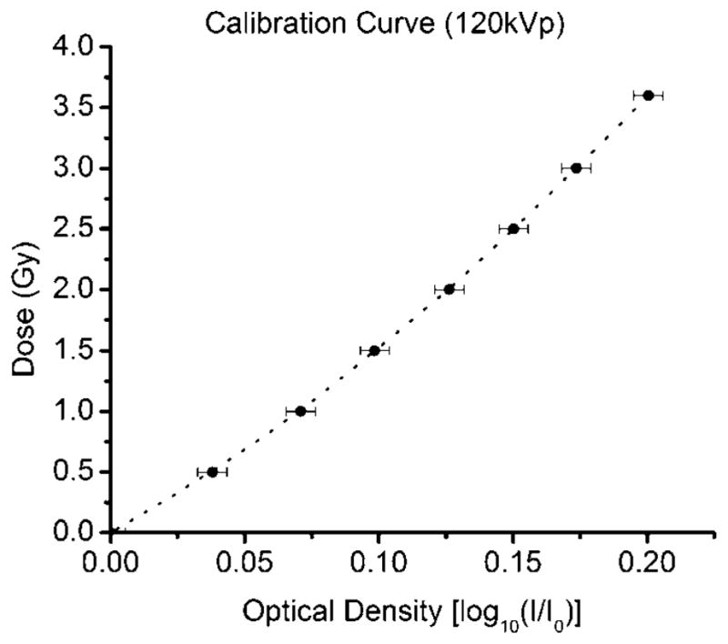
Calibration curve used to associate the dose delivered to the film and its optical density. The curve can be fitted to a third order polynomial. The error bar represents the standard deviation in reading the film and calculating the optical density, STD = 0.0054.
| (2) |
where I0 is the light transmitted through an unused film (base + fog only) and I is the light transmitted through the irradiated film. Log10(I) and Log10(I0) are represented by the pixel value of the irradiated film and the unused film, respectively. The calibration curve can be fitted well with a third order polynomial.
3.3. Dose rate as a function of field diameter
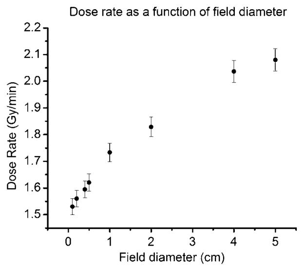
Figure 4 shows the dose rate at the isocenter at 1 mm depth in solid water as a function of field diameter. The error bars represent the average standard deviation obtained for all points (3.6%). The dose rate ranges from 1.56 Gy min−1 to 2.08 Gy min−1 for field diameters between 0.1 and 5 cm, respectively. The dose rate decreases approximately 26% when the collimator aperture is reduced from 5.0 cm to 0.1 cm.
Figure 4.
Dose rate as a function of the field diameter. The dose rate decreases as the field diameter decreases due to scatter reduction. The contribution of scatter to the primary beam is significant at the energies at which the microCT operates. The error bars represent the overall uncertainty in the film measurements, 3.6%.
3.4. Contribution of scatter coming from the plastic bore and collimators
Air kerma measured with the pinpoint chamber for field diameters ranging from 1.0 cm to 5.0 cm did not show any variation. This suggests that the contribution of scatter from the bore tube and the collimator to the primary beam is negligible. The standard deviation of measurements in that field diameter range was 0.9% which can be attributed to beam fluctuation. The AAPM TG-61 protocol presents backscatter factors for different energies, source–surface distances and field diameters. For the same half value layer of the microCT beam and for a source–surface distance equal to the isocenter distance, the backscatter factor for field diameters of 1.0, 2.0 and 5.0 cm are 1.059, 1.120 and 1.242, respectively. The backscatter ratios of the field diameter of 1.0 cm with respect to 2.0 and 5.0 cm are 0.945 and 0.853, respectively. The ratios of the measured dose rate of the field diameter of 1.0 cm with respect to 2.0 and 5.0 cm are 0.945 and 0.832, respectively (table 2). This suggests that the variation of the dose rate as a function of field diameter is primarily due to the variation in the backscatter produced when photons interact with the solid water.
Table 2.
Backscatter factor ratio and measured dose rate ratio. The variation of the dose rate as a function of the field diameter is basically due to the variation in the backscatter produced when photons interact with the solid water.
| Field diameter (cm) | AAPM TG-61 backscattera | Backscatter ratio (normalized to the field diameter of 1 cm) | Measured dose rate ratio (normalized to the field diameter of 1 cm) |
|---|---|---|---|
| 5.0 | 1.242 | 0.852 | 0.832 |
| 2.0 | 1.120 | 0.945 | 0.945 |
| 1.0 | 1.059 | 1 | 1 |
Backscatter factors for a HVL = 5.6 mmAl and a source–surface distance of 35.4 cm.
The protocol does not present any data for field diameters smaller than 1 cm. However, if we assume the field diameter of 0.2 cm as a pencil beam, the backscatter factor would be 1.000 and the ratio with the backscatter factor for a field diameter of 5 cm would be 0.80. Using the measured dose rate, that ratio is 0.75. At very small field sizes, the penumbra is expected to limit the dose rate as the size of the beam becomes comparable to or smaller than the size of the penumbra. However, from the data we have obtained, this system is able to deliver dose rates suitable for radiotherapy at field sizes as small as 2 mm.
3.5. Dose rate as a function of depth
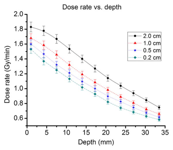
Figure 5 shows the dose rate as a function of depth for field diameters of 0.2, 0.5, 1.0 and 2.0 cm. The depth of maximum dose is between the surface and 1 mm depth. However, film has neither the spatial resolution nor the sensitivity to measure the depth of maximum dose. One millimeter depth will be taken as the depth of maximum dose based on the following assumptions: (1) 1 mm depth is the shallowest depth that we can measure using film dosimetry, (2) uncertainty on the detector is higher than any dose variation between the surface and 1 mm depth, and (3) calculations of doses delivered to small animal subjects will be done at a minimum of 1 mm depth, even for subcutaneous tumors. For field diameters of 0.5 and 1.0 cm, appropriate field sizes for mice irradiation, the dose rate decreases by about 10% per every 5 mm in depth. The dose rate is adequate to irradiate targets inside of mice considering that the widest part of the mouse abdomen has an approximate radius of about 1.25 cm. The dose rate decreases more slowly for field diameters larger than 1.0 cm, and slightly faster for field diameters smaller than 0.5 cm. The depth dose curve for 2.0 cm presents a shoulder that is not evident at a field diameter of 0.2 cm. This is due to the fact that the backscatter for field diameters of 2.0 cm is significantly higher than backscatter for 0.2 cm.
Figure 5.
Dose rate as a function of depth for field diameters of 2, 1, 0.5 and 0.2 cm. For field diameters of 1.0 cm and 0.5 cm, the most commonly used field diameter range used in mice irradiation, the dose rate decreases about 10% per every 5 mm in depth. The dose rate is still high enough to irradiate targets inside of mice bodies considering that the average radius of a mouse’s body is about 1.25 cm. The error bar represents the overall uncertainty in the film measurements, 3.6%.
3.6. Flatness, symmetry, FWHM and penumbra
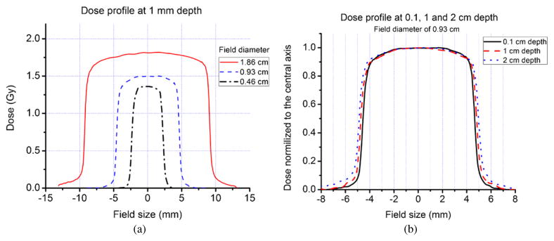
Figure 6(a) shows the 120 kVp photon beam dose profile at 1 mm depth for field diameters of 0.5, 1.0 and 2.0 cm. Field diameters were set at the isocenter but the film was placed at 2.5 cm above the isocenter to increase the dose rate. Therefore, the actual field diameters are 0.46, 0.93 and 1.86 cm. Table 3 presents the measured values of penumbra and FWHM. It also provides the calculated values of flatness and symmetry of the beam. The beam exhibits good symmetry for field diameters smaller than 2.0 cm. The heel effect was not significant for the field diameters studied. The dose profiles exhibit shoulders, but are sufficiently flat to deliver dose homogenously at 75% of the cross-area. The beam has a very sharp penumbra. However, the observed penumbra serves to limit the dose rate beyond scatter reduction when field sizes are reduced to less than 0.2 cm.
Figure 6.
(a) Dose profile at 1 mm depth for field diameters of 0.46, 0.93 and 1.86 cm (120 kVp, 50 mA photon beam). (b) Dose profile at 0.1, 1 and 2 cm depth for a field diameter of 0.93 cm. The FWHM of the beam increases to 0.95 and 1.01 cm at depths of 1 and 2 cm, respectively. Penumbra, flatness and symmetry do not change significantly.
Table 3.
Flatness, symmetry, FWHM and penumbra for filed diameters of 0.46, 0.93 and 1.86 cm. Measurements were performed with gafchromic EBT film at 1 mm depth in solid water. In general, the photon beam has dosimetric characteristics sufficient to homogenously irradiate targets within mice.
| Field diameter |
|||
|---|---|---|---|
| 2.0 cm | 1.0 cm | 0.5 cm | |
| Flatness (%) | 3.4 | 3.6 | 3.7 |
| Symmetry (%) | 1.0 | 1.0 | 0.1 |
| Penumbra (Film) (mm) | 0.60 ± 0.05 | 0.45 ± 0.05 | 0.45 ± 0.05 |
| Penumbra (CT detector) (mm) | 0.50 ± 0.05 | 0.50 ± 0.05 | 0.50 ± 0.05 |
| Field diameter at film (mm) | 1.86 | 0.93 | 0.46 |
| FWHM | 1.83 ± 0.05 | 0.92 ± 0.05 | 0.46 ± 0.05 |
The field diameter set in the collimator and the field diameter measured with film at 1 mm depth agreed to within 1.6%. The radiation field diameter increases to 0.95 and 1.01 cm at depths of 1 and 2 cm, respectively (figure 6(b)). This increase is mainly due to the divergence of the beam, with some contribution from lateral photon scatter. The uncertainties in penumbra and FWHM reflect the size of the pixel in the acquired images. In general, the photon beam has adequate dosimetric characteristics to homogenously irradiate targets within small animal subjects.
3.7. Dose delivery evaluation
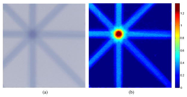
A film–solid water phantom was irradiated with eight beams with diameters of 0.2 cm. The calculated dose delivered at the intersection of the beam axes was 1.40 Gy. Using the calibration curve and the film optical density (OD) in the intersection of the beams as the input, the measured dose delivered to the film was 1.36 Gy. The difference between the calculated and measured dose is 2.8%. Figure 7 shows the irradiated film and the image of the dose distribution in the film. This evaluation demonstrates that the dosimetry of the system is consistent and that it can be used to calculate irradiation time when delivering dose to experimental subjects.
Figure 7.
(a) Film irradiated with eight beams with diameters of 0.2 cm. (b) Dose distribution in the film. The difference between the calculated and measured dose is 2.8%. This single dose testing proved that the dosimetry of the system was consistent and that it can be used to deliver the dose to internal organs in mice.
3.8. Error analysis
The dose delivered to a specimen is calculated based on the air kerma rate at the isocenter of the microCT. The air kerma rate has been measured as accurately as possible, but in general, the result of the measurement is only an estimation of the true value. The result is complete only when the confidence level of the value is well known. In other words, the result must be accompanied by a quantitative statement of its uncertainty associated with the measurements (Taylor and Kuyatt 1994). The total uncertainty should include random and systematic errors in the measurement process. The total uncertainty of the air kerma rate at the isocenter of the microCT represents the combined uncertainty of type A and type B uncertainties determined over the entire calibration procedure. It includes uncertainty due to fluctuations in the photon beam, uncertainty of the detector position and uncertainty of detector sensitivity. The uncertainties involved in the dose rate measurement, using an ion chamber, are shown in table 4. The type A uncertainties were determined based on statistical analysis (standard deviation), whereas the type B uncertainty was based on previous measurement data, manufacturer’s specifications and data provided in calibration and other reports. Scientific judgment was also used to estimate or assign probability distributions over the limits in parameters provided by the manufacturer’s specifications. The values for the standard uncertainty types A and B are 0.3% and 2.4%, respectively. The value for the combined uncertainty is 2.4%. The expanded uncertainty at a coverage factor of k = 2 is, therefore, 4.8%. When using film dosimetry, the overall uncertainty was estimated as 3.6%, including uncertainties in acquiring the measurements and analyzing the film. The expanded uncertainty at a cover factor of k = 2 is therefore 7.2%.
Table 4.
Uncertainty of the dose rate measured at the isocenter of the microCT using an ion chamber. Type A uncertainties are determined based on statistical analysis, whereas type B uncertainties are based on previous measurements, manufacturer’s specifications, and data provided in calibration and other reports. The combined uncertainty and the expanded uncertainty at a cover factor of k = 2 are 2.4% and 4.8%, respectively.
| Type A (%) | Type B (%) | |
|---|---|---|
| Air kerma calibration factor | 2.0 | |
| X-ray beam fluctuation | 0.9 | |
| Position | 1.0 | |
| Ion chamber readings | 0.3 | |
| Electrometer | 0.3 | |
| Uncertainty | 0.3 | 2.4 |
4. Conclusion
The main goal of this study was to investigate the dosimetric characteristics of the 120 kVp photon beam of a GE eXplore microCT modified to have therapy capabilities. When the x-ray tube operates at the maximum tube current, 50 mA, the dose rate at the isocenter ranges from 1.56 to 2.13 to 1.56 Gy min−1 at 1 mm beneath the water surface for field diameters between 0.2 and 6.0 cm. This dose rate is sufficiently large to deliver dose in mice in reasonable period of time. For field diameters ranging between 0.5 and 1.0 cm, the dose rate decreases roughly 10% per every 5 mm depth, which makes the beam suitable to irradiate targets within the bodies of mice. The beam has adequate flatness, symmetry and sharpness to accurately conform dose distribution on target organs on mice, and the irradiation field size is affected mainly by the divergence of the beam. The method to calculate irradiation time presented in this paper is based on the dose rate at the central axis of the beam and the dose delivered at the center of the target. Testing was performed only in two dimensions, but due to the acceptable flatness and symmetry of the beam, we can suggest that the dose distribution has acceptable homogeneity over 80% of the irradiated volume. Efforts are now in progress to produce a treatment planning system for this microCT/RT device using RT Image (Graves et al 2007b), which will incorporate the commissioning data presented here and calculate irradiation time based on the integral dose delivered to the gross tumor volume (GTV). The work presented in this paper is being used as the dosimetric platform to validate the beams generated with Monte Carlo simulation that will be used for calculation in the treatment planning software. We are investigating strategies to increase the dose rate of the system. The dose rate ranges from 1.56 to 2.13 Gy min−1, but the system is limited by both the duty cycle of the pulsed x-ray beam and the output capacity of the electrical generator. Further modifications to the system (new x-ray tube, generator, cooling solutions) have been proposed to improve the dose rate. At this time, the system is capable of delivering doses of up to 8 Gy without either overstressing the system or keeping the subject anesthetized for excessively long periods (>2 h). Positioning, scanning, image reconstruction and dose delivery are performed in less than 1 h for doses lower than 8 Gy. In general, the beam has appropriate dosimetric characteristics to accurately deliver doses up to 8 Gy to organs inside mice. The dose is precisely delivered in a tomotherapy style with field diameters as small as 2 mm. The 3D stage, collimator and gantry are computer controlled, making the system adaptable to intensity-modulated radiation therapy strategies. This microCT/RT system is a feasible tool to irradiate mice with modalities and treatment plans similar to those achieved for humans.
Acknowledgments
The authors would like to acknowledge the assistance of Dr Jan Seuntjens of McGill University for his assistance in devising the dosimetry protocol and interpreting the acquired data.
References
- Bouchet L, Meeks S, Goodchild G, Bova F, Buatti J, Friedman W. Calibration of three-dimensional ultrasound images for image-guided radiation therapy. Phys Med Biol. 2001;46:559–77. doi: 10.1088/0031-9155/46/2/321. [DOI] [PubMed] [Google Scholar]
- Butson M, Cheung T, Yu P. Weak energy dependence of EBT gafchromic film dose response in the 50 kVp–10 MVp x-ray range. Appl Radiat Isot. 2006;64:60–2. doi: 10.1016/j.apradiso.2005.07.002. [DOI] [PubMed] [Google Scholar]
- Cheung T, Butson M, Yu P. Post-irradiation colouration of Gafchromic EBT radiochromic film. Phys Med Biol. 2005;50:N281–5. doi: 10.1088/0031-9155/50/20/N04. [DOI] [PubMed] [Google Scholar]
- Chiu-Tsao S-T, Ho R, Shankar R, Wang L, Harringson L. Energy dependence of response of new high sensitivity radiochromic films for megavoltage and kilovoltage radiation energies. Med Phys. 2005;32:3350–4. doi: 10.1118/1.2065467. [DOI] [PubMed] [Google Scholar]
- Chow J, Leung M. Treatment planning for small animal using Monte Carlo simulation. Med Phys. 2007;34:4810–7. doi: 10.1118/1.2805254. [DOI] [PubMed] [Google Scholar]
- Dawson L, Jaffray D. Advance in image-guided radiation therapy. J Clin Oncol. 2007;25:938–46. doi: 10.1200/JCO.2006.09.9515. [DOI] [PubMed] [Google Scholar]
- Deng H, Kennedy C, Armour E, McNutt T, Tryggestad E, Ford E, Iordachita I, Kazanzides P, Huang J, Wong J. The small-animal radiation research platform (SARRP): focused pencil beam dosimetry. Med Phys. 2006;33:2241. [Google Scholar]
- DesRosiers C, et al. Use of the Leksell Gamma Knife for localized small field lens irradiation in rodent. Technol Can Res Treat. 2003;2:449–54. doi: 10.1177/153303460300200510. [DOI] [PubMed] [Google Scholar]
- Ford E, Kennedy C, McNutt T, Armour E, Iordachita I, Kazanzides P, Wong J. The small animal radiation research platform: benchtop cone-beam CT. Med Phys. 2006;33:2017. [Google Scholar]
- Fuss M, Sturtewagen E, DeWagter C, Georg D. Dosimetric characterization of GafChromic EBT film and its implication on film dosimetry quality assurance. Phys Med Biol. 2007;52:4211–25. doi: 10.1088/0031-9155/52/14/013. [DOI] [PubMed] [Google Scholar]
- Graves E, Chatterjee R, Keall P, Gambhir S, Contag C, Boyer A. Design and evaluation of a variable aperture collimator for conformal radiotherapy of small animals using a microCT scanner. Med Phys. 2007a;34:4359–67. doi: 10.1118/1.2789498. [DOI] [PubMed] [Google Scholar]
- Graves E, Quon A, Loo B. RT Image: an open source tool for investigating PET in radiation oncology. Technol Cancer Res Therapy. 2007b;6:111–21. doi: 10.1177/153303460700600207. [DOI] [PubMed] [Google Scholar]
- Hranitzky E, Almond P, Suit H, Moore E. A Cesium-137 irradiator for small laboratory animals. Radiology. 1973;107:641–4. doi: 10.1148/107.3.641. [DOI] [PubMed] [Google Scholar]
- Jaffray D. Emergent technologies for 3D image-guided radiation delivery. Semin Radiat Oncol. 2005;15:208–16. doi: 10.1016/j.semradonc.2005.01.003. [DOI] [PubMed] [Google Scholar]
- Jaffray D, Moseley D, Chow J, Kim S, Ansell S, Wilson G, Chiarot C. An imaged-guided irradiator for pre-clinical radiation therapy studies. Med Phys. 2006;33:2241. [Google Scholar]
- Khan M, Hill R, Van Dyk J. Partial volume rat lung irradiation: an evaluation of early DNA damage. Int J Rad Oncol Biol Phys. 1998;40:467–76. doi: 10.1016/s0360-3016(97)00736-0. [DOI] [PubMed] [Google Scholar]
- Khan M, Van Dyk J, Yeung I, Hill R. Partial volume rat lung irradiation; assessment of early DNA damage in different lung regions and effect of radical scavengers. Radiother Oncol. 2003;66:95–102. doi: 10.1016/s0167-8140(02)00325-0. [DOI] [PubMed] [Google Scholar]
- Laub W, Wong T. The volume effect of detectors in the dosimetry of small fields used in IMRT. Med Phys. 2003;30:341–7. doi: 10.1118/1.1544678. [DOI] [PubMed] [Google Scholar]
- Ma C, Coffey C, DeWerd L, Liu C, Nath R, Seltzer S, Seuntjens J. AAPM protocol for 40–300 kV x-ray beam dosimetry in radiotherapy and radiobiology. Med Phys. 2001;28:868–93. doi: 10.1118/1.1374247. [DOI] [PubMed] [Google Scholar]
- Nath R, Biggs P, Bova F, Ling C, Purdy J, Geinj J, Weinhous M. AAPM code of practice for radiotherapy accelerators: report of AAPM Radiation Therapy Task Group no 45. Med Phys. 1994;21:1093. doi: 10.1118/1.597398. [DOI] [PubMed] [Google Scholar]
- Niroomand-Rad A, Blackwell C, Coursey B, Gall K, Galvin J, McLaughlin W, Meigooni A, Nath R, Rogers J, Soares C. Radiochromic film dosimetry: recommendations of AAPM Radiation Therapy Committee Task Group 55. Med Phys. 1998;25:2093–115. doi: 10.1118/1.598407. [DOI] [PubMed] [Google Scholar]
- Stojadinovic S, et al. MicroRT/MicroRTP: a conformal small animal planning and radiation system. Med Phys. 2006a;33:2273. [Google Scholar]
- Stojadinovic S, et al. MicroRT—small animal conformal irradiator. Med Phys. 2007;34:4706–15. doi: 10.1118/1.2799887. [DOI] [PubMed] [Google Scholar]
- Stojadinovic S, Low D, Vivic M, Mutic S, Deasy J, Hope A, Parikh P, Grigsby P. Progress toward a microradiation therapy: small animal conformal irradiator. Med Phys. 2006b;33:3834–45. doi: 10.1118/1.2349693. [DOI] [PubMed] [Google Scholar]
- Stojadinovic S, Low D, Vivic M, Mutic S, Gribsby P, Deasy J, Hope A. Progress towards a MicroRT small animal conformal irradiator. Med Phys. 2005;32:2063. doi: 10.1118/1.2799887. [DOI] [PubMed] [Google Scholar]
- Sugiyama K, Nakatsuji A, Ochiai H, Esumi H, Matsumura Y. Mechanism of impairment in wound healing of electron beam-irradiated rat skin. Wound Rep Reg. 2005;13:A5-A. [Google Scholar]
- Swicord M, Morrissey J, Zakharia D, Ballen M, Balzano Q. Dosimetry in mice exposed to 1.6 GHz microwaves in a carrousel irradiator. Bioelectromagnetics. 1999;20:42–7. doi: 10.1002/(sici)1521-186x(1999)20:1<42::aid-bem6>3.0.co;2-t. [DOI] [PubMed] [Google Scholar]
- Takahashi S, Sun XZ, Kubota Y, Takai N, Nojima K. Histological and elemental changes in the rat brain after local irradiation with carbon ion beams. J Rad Res. 2002;43:143–52. doi: 10.1269/jrr.43.143. [DOI] [PubMed] [Google Scholar]
- Taylor B, Kuyatt C. NIST Technical Note 1297. National Institute of Standards and Technology; USA: 1994. Guidelines for evaluating and expressing the uncertainty of NIST measurement results. [Google Scholar]
- Todorovic M, Fisher M, Cremers F, Thom E, Schmidt R. Evaluation of Gafchromic EBT prototype B for external beam dose verification. Med Phys. 2006;33:1321–8. doi: 10.1118/1.2188077. [DOI] [PubMed] [Google Scholar]
- Tryggestad E, et al. The small-animal radiation research platform (SARRP): commissioning a 225 kVp ‘small field’ x-ray source for Monte Carlo-based treatment planning. Med Phys. 2006;33:2241. [Google Scholar]
- Zhou H, Chatterjee R, Contag C, Gambhir S, Boyer A, Keall P, Graves E. Development of a variable-aperture collimator for small animal radiation therapy. Med Phys. 2007;34:2436. doi: 10.1118/1.2789498. [DOI] [PubMed] [Google Scholar]


