Abstract
In this study, we investigated the feasibility of an intracranial catheter transducer with dual-mode capability of real-time 3D (RT3D) imaging and ultrasound hyperthermia, for application in the visualization and treatment of tumors in the brain. Feasibility is demonstrated in two ways: first by using a 50-element linear array transducer (17 mm × 3.1 mm aperture) operating at 4.4 MHz with our Volumetrics diagnostic scanner and custom electrical impedance matching circuits to achieve a temperature rise over 4°C in excised pork muscle, and second by designing and constructing a 12 Fr, integrated matrix and linear array catheter transducer prototype for combined RT3D imaging and heating capability. This dual-mode catheter incorporated 153 matrix array elements and 11 linear array elements diced on a 0.2 mm pitch, with a total aperture size of 8.4 mm × 2.3 mm. This array achieved a 3.5°C in vitro temperature rise at a 2 cm focal distance in tissue-mimicking material. The dual-mode catheter prototype was compared with a Siemens 10 Fr AcuNav™ catheter as a gold standard in experiments assessing image quality and therapeutic potential, and both probes were used in a canine brain model to image anatomical structures and color Doppler blood flow and to attempt in vivo heating.
Keywords: catheter transducer, real-time 3D imaging, ultrasound hyperthermia, dual-mode array
Introduction
The American Cancer Society estimates that in the United States, 21,810 new cases of primary malignant brain and central nervous system (CNS) tumors were diagnosed in 2008, and 13,070 people died from this condition—comprising just over 2% of all cancer deaths.1 The Central Brain Tumor Registry of the United States estimates that in the year 2000, more than 81,000 persons in the U.S. were living with a primary malignant brain/CNS tumor diagnosis.2 Malignant gliomas account for 81% of all malignant primary brain/CNS tumors, and 51% of gliomas are of the WHO grade IV subtype glioblastoma multiforme (GBM), the most common intracranial neoplasm.2,3
Currently, primary brain tumors are most commonly treated by surgery, radiotherapy, and chemotherapy.4 Chemotherapy may be administered systemically, by mouth or intravenous infusion, or locally, by direct intra-arterial or interstitial injection into a tumor target.5 The major challenge to effectively delivering drugs to CNS tumors is to achieve a high drug concentration within the tumor bed by overcoming the physiological blood-brain barrier, the dynamic interface that protects the brain and also actively extrudes drugs from the brain through active drug efflux transporters.6
Blood-brain barrier (BBB) disruption must be transient and reversible—rapid closure of the barrier after disruption effectively traps drug within the tissue.7,8 High-intensity focused ultrasound (HIFU) has been studied as a method for achieving this effect.9-11 The use of low-pressure ultrasound (e.g. peak negative pressure amplitudes of 0.4-1.5 MPa) at low diagnostic frequencies (0.26-2.04 MHz), in conjunction with microbubble contrast agent such as Optison or Definity, has also been shown to achieve localized BBB disruption.12-14 Mild hyperthermia (41°C) using ultrasound (20 min, 0.4 W/cm2) has been shown to reversibly enhance passive diffusion of hydrophobic drugs through microvessel endothelial cell monolayers, allowing the drugs to bypass efflux transporters and demonstrating the ability to permeate the BBB.15
Efforts to develop trans-cranial, image-guided focused ultrasound systems for brain tumor ablation have shown encouraging results; however, these studies, as well as the aforementioned BBB disruption experiments, have concerns associated with the skull—either a highly invasive approach is taken, where the skull bone must be removed prior to sonication, or a noninvasive approach is taken, where the high ultrasound attenuation and reflection from the bone is accepted and the phase aberration from the skull's variable thickness is either managed or corrected.16-19
Minimally-invasive endovascular techniques for treatment of various intracranial diseases, including arteriovenous malformation, intracranial aneurysm, and dural venous sinus thrombosis, have been used in the field of interventional neuroradiology, and these procedures can be extended to the treatment of intracranial tumors.20,21 For treatment of cerebral venous thrombotic disease, a 7 Fr to 9 Fr introducer sheath or guide catheter may be used for access, usually via a transfemoral approach or a direct retrograde internal jugular stick, and a 5 Fr catheter may be inserted as far as the frontal portion of the superior sagittal sinus.20-22 Case reports detailing the use of catheter devices in the dural venous sinuses to treat thrombosis (by urokinase infusion or rheolytic thrombectomy) demonstrate the feasibility of this approach.23-27
Dual-mode ultrasound transducers for image-guided therapy have been designed and implemented for several thermal applications, including treatment of cardiac arrhythmias and tumors of the liver, breast, biliary ducts, and prostate.28-33 These have been developed with a catheter, endoscope, or extracorporeal approach, using either a single element or phased array for therapy—phased arrays allow for the most control over the energy deposition pattern of ultrasound.34 Ultrasound, when compared with magnetic resonance (MR) imaging, is an attractive modality for guidance and treatment monitoring, because of its low cost, portability, and high frame rate.32,33 Dual-mode imaging/therapy arrays are desirable because of the inherent spatial registration between imaging, treatment, and monitoring.35 For example, miniaturized linear arrays, using a 2.3 mm × 49 mm aperture at 3.1 MHz, have been developed for minimally invasive interstitial thermal treatment and imaging of liver tissue.28
In the 1990's, real-time 3D (RT3D) ultrasound imaging was developed at Duke University for transthoracic cardiac applications and more recently for intracardiac catheters, intravascular catheters, endoscopes, laparoscopes, 3D ultrasound guidance of surgical robotics, 3D transcranial ultrasound, and 3D intracranial ultrasound endoscopes for neurosurgery and needle guidance in the brain.30,36-45 Our Duke/Volumetrics Medical Imaging, Inc. (Durham, NC, USA) 3D ultrasound system scans a 65°-120° pyramid using a matrix array transducer to produce 3D scans at rates of 30 volumes/sec. Real-time display options in our 3-D scanner include up to five image planes oriented at any desired angle and depth within the pyramidal scan, as well as real-time 3D volume rendering, 3D steerable pulsed Doppler, and 3D color Doppler flow imaging.
The development of microbubble ultrasound contrast agents (UCAs) and temperature-sensitive liposomes for targeted imaging and targeted drug delivery is also proceeding rapidly. Microbubble UCAs are blood pool agents, mean size of 0.1-2 microns, administered via intravenous injection such that only 0.1 mL increases the signal of blood vessels by over a factor of 10, enabling detection of capillary-sized vessels. The contrast microbubbles are used clinically in cardiac exams and in experimental perfusion studies of kidney, transcranial brain, and liver, and blood flow measurements of breast, prostate, and liver tumors.46,47 UCAs offer the advantage of portable, inexpensive, real-time use without ionizing radiation, and are thus ideal for serial studies as in treatment monitoring. Liposomes are membrane-enclosed vesicles composed of a lipid bilayer shell (which can trap hydrophobic and amphipathic drugs) surrounding an aqueous core (which can contain hydrophilic drugs), with a diameter typically near 100 nm.48 Liposomes can be readily conjugated to antibodies or other adhesion ligands, and UCAs can also be chemically modified to enable active targeting of tumor angiogenesis; for example, ultrasound molecular imaging of tumor angiogenesis in a rat after intravenous injection of microbubbles targeted to αvβ3 integrins has demonstrated enhancement of a primary glioblastoma and a small metastasis.49 Hybrid drug delivery vehicles, conjugating liposomes and microbubbles, are also under investigation.48 Temperature-sensitive liposomes containing the cancer drug doxorubicin have been shown to quickly release their contents when the surrounding temperature is raised to 41°C, or 4°C above normal body temperature.50 Therefore, temperature-sensitive liposomes, in combination with local hyperthermia (which may be created and directed by ultrasound), provide targeted control of drug release that may augment chemotherapeutic efficacy in many clinical settings.50,51
The goal of this project is to extend real-time 3D ultrasound to minimally invasive catheters for intracranial imaging of the brain and ultrasound hyperthermia for neuro-oncology. This technology could be used to visualize a tumor target in 3D and then trigger the release of chemotherapeutic drugs contained within microbubble or liposomal agents molecularly targeted to regions of tumor angiogenesis. The catheter will be designed to be both thin and flexible enough to be manipulated through the internal jugular vein into the dural venous sinuses (as shown in Figure 1), which provide minimally invasive access to virtually the entire brain volume.
Fig. 1.
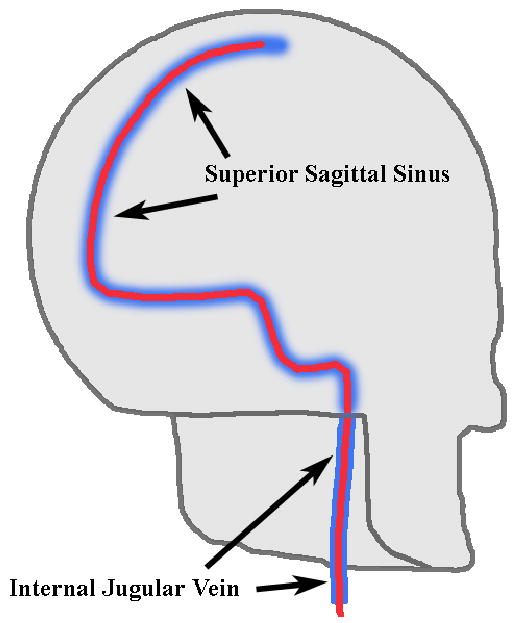
Intended catheter pathway affording minimally-invasive access to the brain volume via dural venous sinuses.
In this paper, we describe a series of experiments conducted in an effort to demonstrate proof of concept. An initial prototype dual-mode (RT3D imaging & hyperthermia) catheter transducer was designed and constructed to determine the feasibility of our long term goal. The imaging and thermal performance of the dual-mode prototype was compared with a Siemens (Siemens Medical Solutions, Ultrasound Division, Issaquah, WA, USA) AcuNav™ catheter in in vitro experiments and in an in vivo canine brain model, with access to the superior sagittal sinus afforded through a 1 cm burr hole in the skull.
Methods
The transducer array we propose integrates a 2D matrix array, which can acquire 3D scans, with adjacent linear arrays, which contribute power to a beam for inducing hyperthermia, as shown in Figure 2.
Fig. 2.
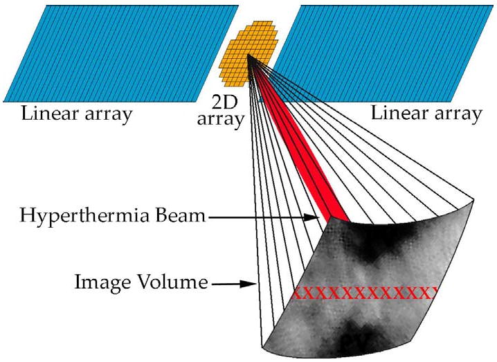
Integrated 2D matrix & linear array design for RT3D imaging & hyperthermia. The centered 2D array scans a pyramidal volume in real-time, and the adjacent linear arrays produce a hyperthermia beam (shown in red within the volume), steerable in azimuth (different possible foci indicated by red ‘x’s).
Preliminary Experiment: Hyperthermia with RT3D Scanner
To establish the feasibility of a dual-mode imaging/therapy catheter transducer, we first sought to demonstrate that our diagnostic RT3D Volumetrics scanner could be used to achieve and maintain a sufficient temperature rise (≥ 4°C). In this preliminary experiment, a 50 channel, 4.4 MHz PZT-5H, 17 mm × 3.1 mm linear array transducer previously described was used with electrical impedance matching circuits customized for each channel in order to maximize power transfer from the scanner to the transducer elements.52 The matching circuits were simple ‘L-section’ networks consisting of two reactive components: an inductor in series with the load, and a capacitor in parallel. To design these networks, the system (source) impedance and the corresponding water-coupled transducer element (load) impedance were measured at the chosen operating frequency, for each channel. Then, because maximum real power transfer occurs when the input impedance (L-section plus load) equals the complex conjugate of the source impedance, we found the optimal values of inductance and capacitance for the L-section components algebraically. The necessary series inductance ranged from 9 to 30 μH, and the parallel capacitance ranged from 47 to 268 pF.
With the matching circuits in use, the scanner generated a 12-cycle pulse at 6.6 kHz PRF—settings found to yield maximum stable power output—and the spatial-peak, temporal-average intensity (ISPTA) was measured at a 3 cm focal depth with a calibrated membrane hydrophone (S4-251, Sonora Medical Systems, Longmont, CO, USA) in a water tank, in accordance with the procedures outlined in the AIUM/NEMA UD 2-2004 standard.53 A thermocouple (5TC series, Omega Engineering, Inc., Stamford, CT, USA) was used to monitor the scanner's internal temperature during transmit. With the same scanner settings, the hydrophone was replaced by a piece of degassed, excised pork muscle; a type T, 33 gauge, stainless steel hypodermic needle thermocouple (HYP-0, Omega Engineering, Inc.) was inserted approximately 2 mm beneath the surface of the tissue and placed at the focus to measure the achievable temperature rise. The data acquisition system (Integra model 2700, Keithley Instruments, Inc., Cleveland, OH, USA), which contains built-in signal conditioning hardware for filtering and noise reduction, recorded temperature data at a sampling frequency of 3.8 Hz. The tissue temperature rise measurement was replicated four times. The water path between the transducer and the tissue served to isolate the tissue from conductive heating, so as to better correlate temperature measurements with intensity measurements. Possible artifacts associated with this type of thermal measurement are viscous heating, reflections, and conduction along the wire; our small-diameter, fine wire thermocouple sheathed in stainless steel was chosen to minimize these effects, and we disregard them for the proof-of-concept experiments described here.54,55
Integrated Catheter Transducer Design & Fabrication
The results from our preliminary experiment gave us confidence to develop a prototype catheter device integrating a matrix array and a linear array. We used a custom 10 Fr multi-layer flexible circuit made by Microconnex (Snoqualmie, WA, USA) as a construction template. The flex circuit could accommodate an array with 198 matrix elements and 18 linear elements, diced on a 0.2 mm pitch, for a total aperture size of 8.4 mm × 2.3 mm. Two different schemes were considered as methods to achieve optimal tissue heating: one with all the elements (both the matrix and linear arrays) focused at 2 cm driven by the Volumetrics scanner, and one unfocused scheme using only the linear array elements driven by a single-channel, 25-Watt RF power amplifier (Model 525LA, ENI, Rochester, NY, USA) connected to a waveform generator (Model 33250, Agilent, Santa Clara, CA, USA). Both of these schemes used a 4.4 MHz operating frequency.
To aid our design process, the beam pattern for each of these schemes was simulated and compared with that of a Siemens 10 Fr AcuNav catheter probe using Field II.56 The AcuNav is a linear array with 64 elements on a 0.11 mm pitch, for an aperture size of approximately 7.1 mm × 2.5 mm; this array was focused at 2 cm, operating at 5.33 MHz. Each computation included a 0.5 dB/cm/MHz attenuation factor to simulate brain tissue.57 The simulations did not calculate the first 5 mm in front of the transducer because the model is less accurate for very short distances.
Figure 3 illustrates this stage of the design process. Figures 3a, 3b, and 3c show the footprint of the active aperture in each case: the entire integrated array (2 cm transmit focus), the integrated design's linear array elements only (unfocused transmit), and the AcuNav (2 cm transmit focus), respectively. Figures 3d, 3e, and 3f display the beam's relative pressure amplitude in the zero-elevation plane for each case, respectively, and Figures 3g, 3h, and 3i show each beam's relative amplitude at a depth of 2 cm. For the case of the entire integrated array, the -6 dB azimuthal beamwidth was 7.5 mm at 0.5 cm deep. For the case of the integrated design's unfocused linear array elements, the -6 dB beam beamwidth was 7.8 mm at 0.5 cm deep. For the focused AcuNav, the -6 dB beamwidth was 4.6 mm at 0.5 cm deep.
Fig. 3.
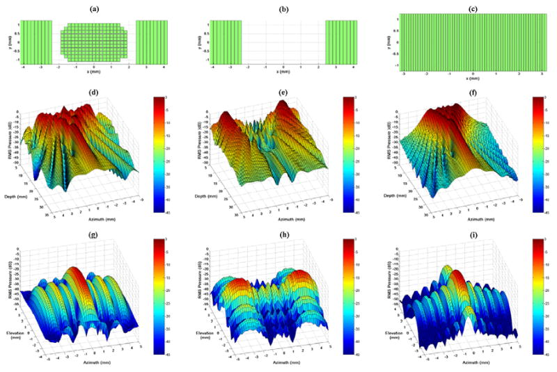
Field II simulation apertures and beam plots. (a,b,c) Active apertures for each case: the entire integrated array with 2 cm focus, the integrated catheter's linear arrays with unfocused transmit, and the AcuNav with 2 cm focus, respectively. (d,e,f) Relative pressure amplitude in the zero-elevation plane for each case, respectively. (g,h,i) Relative pressure amplitude at a depth of 2 cm for each case, respectively.
Fabricating the integrated array involved adapting the flex circuit (shown in Figure 4a), which was initially designed for a matrix array alone 42. A 0.35-mm-thick piece of PZT-5H was bonded to the flex circuit with silver epoxy, slightly overlapping the grid of element contacts onto the bordering ground contact. This piece was diced on a 0.2 mm pitch both vertically and horizontally to create the matrix array on a 19 × 11 element grid. The linear array was then built in the adjacent spaces: first each space was filled with silver epoxy and cured to create a level backside contact, then a piece of PZT-5H was bonded to each side and diced (0.2 mm pitch), physically separating the nine elements on each end. MicroFlat cables from W.L. Gore & Associates, Inc. (Newark, DE, USA) were soldered with appropriate spacing to the exposed border contact, and these solder joints were reinforced with UV-curing epoxy before carefully re-dicing the linear array to ensure electrical separation of the linear array channels (Figure 4b shows the completion of these steps: the 8.4 mm × 2.3 mm total aperture). A layer of double-sided metallized liquid crystal polymer (LCP) was attached to the face of the transducer for a front grounding contact and overall electronic shielding for the transducer. There was no acoustic matching layer for this prototype. MicroFlat cables were soldered to the pads of the flex circuit to connect the matrix array channels, and an acoustic backing was attached before bending the flex circuit into a side-viewing configuration and packaging the transducer into the catheter lumen. The proximal ends of the cables were soldered to custom circuit boards fitted with Samtek, Inc. (New Albany, IN, USA) connectors (model # BSH-060-01-F-D-A) to link with the ultrasound system handle. The complete, packaged transducer is shown in Figure 4c (on a larger scale than Figures 4a and 4b).
Fig. 4.
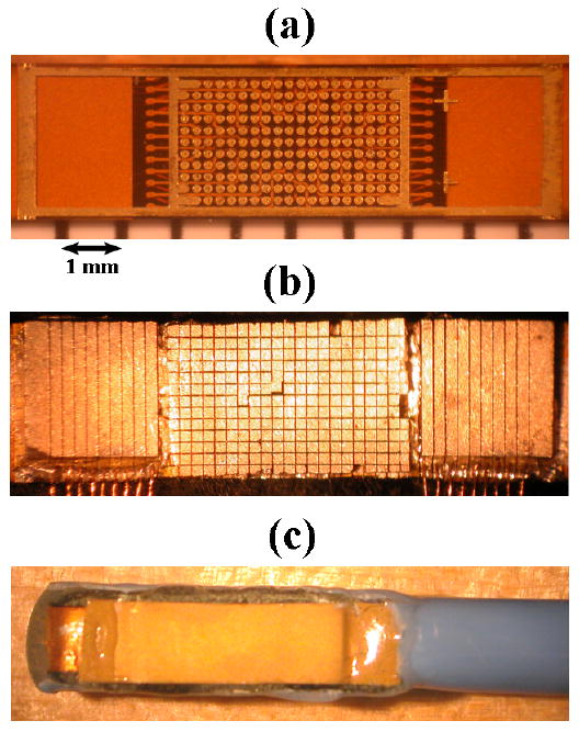
(a) Bare flex circuit above a ruler with mm markings. (b) Diced matrix and linear arrays with MicroFlat cables soldered to linear array contacts. (c) Completed dual-mode catheter transducer.
In Vitro Temperature Measurement
For measurements assessing the prototype dual-mode catheter transducer's hyperthermia capability, tissue-mimicking material from National Physical Laboratory (Teddington, UK) was used as a model, having thermal properties similar to brain tissue.58,59 Because the dual-mode prototype had a smaller aperture than the 50-channel linear array used in our preliminary experiment, a 2 cm focus was chosen instead of 3 cm, to increase focal gain. A hypodermic needle thermocouple was inserted approximately 2 mm beneath the surface and placed at the focus to measure the achievable temperature rise. As before, the water path between the transducer and the target served to isolate the tissue from conductive heating. In order to compare hyperthermia experiments and assess whether the heating was a result of conduction or ultrasound absorption, the maximum heating rate was calculated by dividing by the amount of time taken to achieve the initial 2.0°C of the total temperature rise.
Large Animal Study Protocol
The Institutional Animal Care and Use Committee at Duke University approved the following procedure used on two canine subjects—one for a RT3D imaging study using an earlier matrix array catheter prototype, and one for a combined RT3D imaging and hyperthermia study using the integrated matrix and linear array prototype.60 In each study, an intravenous (IV) line was established in a peripheral vein, and the dog was sedated with thiopental sodium, 20 mg/kg administered intravenously. Anesthesia was induced with inhalation of isoflurane gas 1% to 5 % delivered through a nose cone. The animal was intubated, placed on a water heated thermal pad, and started on a ventilator. A femoral arterial line was placed via a percutaneous puncture or cutdown. Electrolyte and ventilator adjustments were made based on serial electrolyte and arterial blood gas measurements. An IV maintenance drip of D-5 lactated Ringer's solution was started and maintained at 5 mL/kg/min. Blood pressure, lead II electrocardiogram, and temperature were continuously monitored throughout the procedure. The animal was placed in a prone position, the top of the head was shorn, and a scalp incision was made near the skull midline. The skin and muscle were dissected free and retracted to expose the skull. A 1 cm burr hole was carefully drilled through the bone just above the external occipital protuberance to expose the dura mater encasing the superior sagittal venous sinus. An incision in the dura was made and a catheter device was inserted into the superior sagittal sinus; the catheter was advanced and rotated in the vessel to orient and optimize the field of view and identify structures in the cranial cavity using both B-mode and Doppler imaging. For the catheter hyperthermia portion of the study, a second 1 cm burr hole was made approximately 1.5 cm lateral to the midline and the position of the inserted transducer. A type T, 33 gauge, stainless steel hypodermic needle thermocouple was inserted through the exposed dura into the cerebrum to monitor temperature during hyperthermia trials.
Results
Preliminary Experiment: Hyperthermia with RT3D Scanner
With the 50-channel linear array transmitting to a 3 cm focal depth in a water tank, a spatial-peak, temporal-average intensity (ISPTA) of 6.88 W/cm2 was measured with our membrane hydrophone. Using identical scanner settings, we measured a temperature rise of 5.0°C in degassed, excised pork muscle. The scanner's internal temperature remained at an acceptable level as the power output was maintained for several minutes. Figure 5a is a photo of the center of the linear array used in this experiment—note that a gap was left where the matrix array would be according to the integrated design given in Figure 2. The data in Figure 5b show the temperature rise over 4°C within one minute after turn-on, leveling off at about 5°C above the ambient temperature.
Fig. 5.
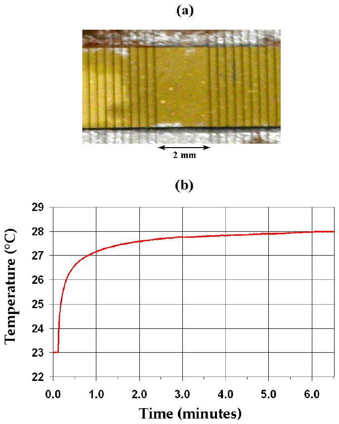
(a) Center of linear array transducer used in in vitro hyperthermia experiment with Volumetrics RT3D scanner and matching circuits. (b) Thermocouple data showing a 5.0°C temperature rise in degassed, excised pork muscle.
In Vitro Imaging & Thermal Performance Tests
The dual-mode RT3D/hyperthermia prototype catheter construction yielded 153 matrix array elements (77% element yield) and 11 linear array elements (61% yield). The dual-mode catheter and Volumetrics scanner were compared with a Siemens 10 Fr AcuNav and SONOLINE Anteres™ system as a gold standard to assess imaging capability and therapeutic potential. Various wire, tumor, and cyst phantoms were imaged with each probe. Figure 6 shows images of a test phantom containing a 1.5 cm diameter cyst, 4 cm deep: Figure 6a is an image taken with the AcuNav at 5.33 MHz, 6b is single-B scan using both the matrix and linear array elements of the integrated catheter array at 3.64 MHz, and 6c, 6d, and 6e are simultaneously acquired coronal, axial, and sagittal planes, respectively, of a 3D scan using only the matrix array elements.
Fig. 6.
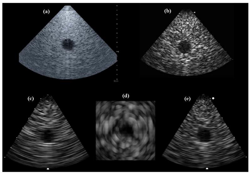
(a) AcuNav image of 4-cm deep, 1.5-cm diameter cyst phantom. (b) Dual-mode catheter single-B scan of cyst phantom. (c,d,e) Dual-mode catheter 3D scan of cyst phantom: coronal, axial, and sagittal image planes.
It should be noted that the concentric ring pattern of the axial image (Figure 6d) is an artifact of the system's scan converter. The speckle patterns in these images show that the prototype dual-mode catheter yielded poorer spatial resolution than the AcuNav due to the reduced aperture and bandwidth of the matrix array for 3D imaging. In addition, the AcuNav showed superior color Doppler sensitivity (as seen in Figure 9b).
Fig. 9.
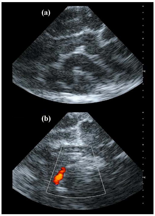
Intracranial AcuNav images. (a) Echo image showing various gyri and sulci of the cerebrum. (b) Color Doppler image showing the internal carotid artery.
To assess the potential of the catheters to create hyperthermia, the maximum spatial-peak, temporal-average intensity was measured in a water tank with our membrane hydrophone. At a transmit focus of 2 cm, the Volumetrics scanner delivered an ISPTA = 2.43 W/cm2 using a 12-cycle, 3.64 MHz pulse at a 6.6 kHz PRF with the dual-mode catheter. An ISPTA = 4.54 W/cm2 was also measured at 1 cm for the case of the unfocused linear array elements driven at 4.6 MHz by a 25-Watt power amplifier. Finally, the AcuNav could deliver a 10-cycle, 5.33 MHz pulse at 6.6 kHz PRF and 55% system voltage as projected maximum settings safe for the system. To avoid potentially damaging self-heating in the AcuNav, ISPTA measurements were taken for lower voltage settings on the Siemens system, and we extrapolated to 55% yielding an estimate of ISPTA = 4.10 W/cm2.
Using the same settings as for the ISPTA = 2.43 W/cm2 data, the dual-mode catheter prototype created a temperature rise of 3.5°C (see Figure 7) at a 2 cm transmit focus in tissue-mimicking material.
Fig. 7.
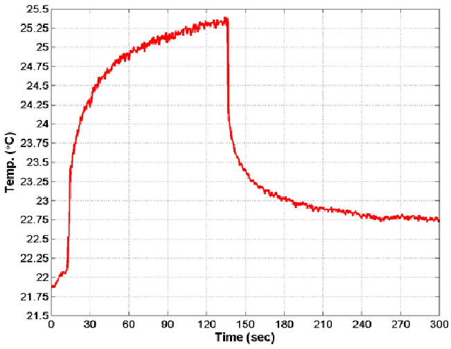
Thermocouple data showing 3.5°C temperature rise in tissue-mimicking material using the dual-mode catheter focused at 2 cm.
This was achieved in less than 2.5 minutes, at which time transmission was halted because some of the scanner's internal electronic components were overheating (above 85°C). It took several minutes for the tissue-mimicking material to dissipate the added heat and return to equilibrium temperature. To avoid risking damage to the scanner, further therapy experiments were carried out with the dual-mode prototype by driving only the linear array elements as a single channel (unfocused) using an external, 25-Watt RF power amplifier connected to a waveform generator. Table 1 shows a complete chart of experimental results.
Table 1.
Intensity and thermal experiment results for 3 arrays and 5 configurations.
| Frequency | Focus | ISPTA (W/cm2) | Temp. Rise (°C) | Max. Heating Rate | ||
|---|---|---|---|---|---|---|
| in vitro | in vivo | |||||
| Linear Array (w/matching circuits) | 4.4 MHz | 3 cm | 6.88 | 5.0 | (N/A) | 0.509°C/sec |
| AcuNav | 5.33 MHz | 2 cm | 4.10* | (N/A) | (N/A) | (N/A) |
| AcuNav | 5.33 MHz | 1 cm | (N/A) | (N/A) | 4.5† | 0.020°C/sec |
| Dual-mode Catheter: All Elements | 3.64 MHz | 2 cm | 2.43 | 3.5 | (N/A) | 0.164°C/sec |
| Dual-mode Catheter: Linear Arrays | 4.6 MHz | unfoc. | 4.54 | (N/A) | 0.87‡ | 0.146°C/sec |
extrapolated estimate
transducer self-heating, conduction
weakened elements
In Vivo Canine Model - Imaging
Each ultrasound catheter was placed in the superior sagittal sinus according to the large animal protocol. Figure 8 is a photo from the surgical procedure showing the exposed skull, with the dual-mode catheter inserted anteriorly into the superior sagittal sinus through the burr hole created on the midline, and the thermocouple inserted medially into the cerebrum through the dura mater exposed by an adjacent burr hole. Both echo and Doppler images were acquired with each probe. The AcuNav produced echo images with clear delineation of cerebral gyri and sulci (Figure 9a), as well as color Doppler images of the internal carotid artery (Figure 9b), acquired without the use of contrast.
Fig. 8.
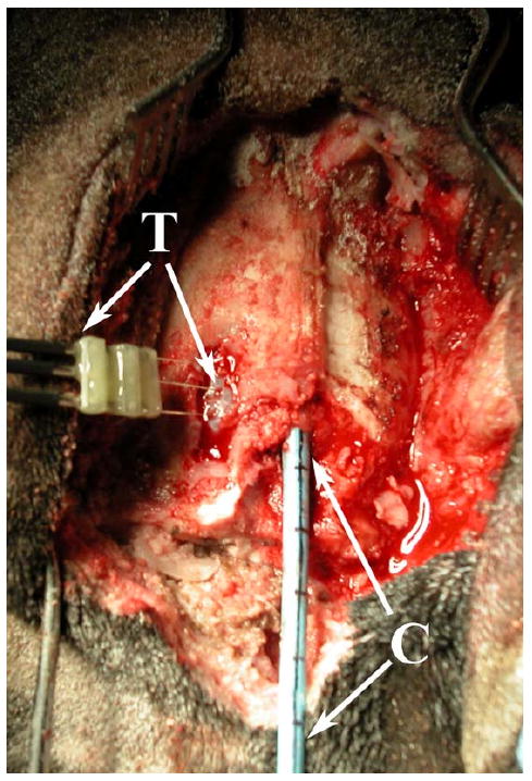
In vivo canine model: the dual-mode catheter (C) placed in the superior sagittal sinus through a burr hole created in the skull, and a thermocouple (T) inserted into the cerebrum through the dura mater exposed by a second burr hole, for hyperthermia trials.
The dual-mode catheter prototype acquired RT3D image data from a pyramidal volume extending from the transducer face toward the base of the cranial cavity. The Volumetrics scanner simultaneously displayed two perpendicular B-mode sectors (sagittal and coronal planes) and two C-scans (axial plane, parallel to the transducer face), which can be inclined at any desired angle. The coronal plane images were found to be very useful for orienting the transducer's field of view, enabling the operator to identify structures more quickly, with greater confidence and accuracy. The lateral ventricles were the most prominent anatomical landmark, and could be clearly seen in all three orthogonal image planes. Due to the limited spatial resolution of the dual-mode catheter, the narrow lumen of the lateral ventricles, and the highly echogenic ventricular walls in the canine, the ventricular lumen does not appear as an echo-free region. The tentorium cerebelli membrane, which separates the cerebellum from the cerebrum, and pulsations of arteries at the base of the brain were also visible. Figures 10a, 10b, and 10c compare simultaneous coronal, axial, and sagittal planes, respectively, versus corresponding anatomical slices.61 The lateral ventricles can be clearly seen in the coronal and axial planes, and the sagittal plane just adjacent to the midline shows the cerebellum, the tentorium, and a posterior horn of the lateral ventricles.
Fig. 10.
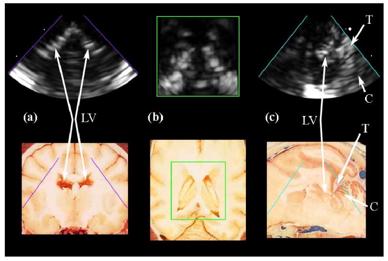
(a,b,c) Intracranial RT3D echo images in coronal, axial, and sagittal planes, respectively, compared to corresponding anatomical images (Reproduced with permission from Fletcher et al., University of Minnesota College of Veterinary Medicine). The lateral ventricles (LV) are clearly seen in (a) and (b). The tentorium (T) and cerebellum (C), as well as a posterior horn of the lateral ventricle, are visible in (c).
For 3D color Doppler imaging, a bolus of agitated saline was needed for contrast and was delivered into the left internal carotid artery.62 Several vessels became visible immediately after the bolus injection, including those that comprise the Circle of Willis. The contrast-enhanced 3D color Doppler scans are shown in Figure 11. To eliminate effects of aliasing due to undersampling, the color Doppler look-up table was modified to display only a single hue, to better visualize the vessels (albeit eliminating directional flow information). Figure 11a is the coronal plane of the scan, clearly showing the anterior communicating artery and left middle cerebral artery, as well as the left and right internal carotid arteries. Figure 11b shows the Circle of Willis, including the anterior, middle, and posterior cerebral, anterior and posterior communicating arteries, in an axial image plane. Figure 11c is a sagittal plane of the scan, showing the left internal carotid, middle and posterior cerebral, and posterior communicating arteries. Figure 11d is an anatomical diagram showing a latex-injected sheep brain of similar scale for reference.63
Fig. 11.
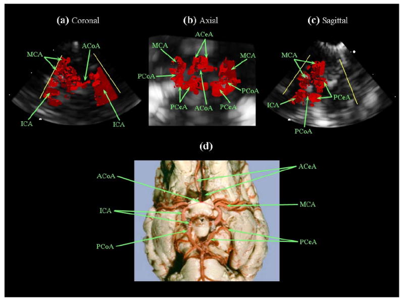
(a,b,c) Intracranial RT3D color Doppler images in coronal, axial, and sagittal planes, respectively (note: the color Doppler look-up table was modified, eliminating directional flow information). (d) Latex-injected sheep brain vasculature for anatomical reference (Reproduced with permission from R.R. Miselis, University of Pennsylvania School of Veterinary Medicine). The internal carotid arteries (ICA), left middle cerebral artery (MCA), and anterior communicating artery (ACoA) are visible in (a). The Circle of Willis is shown in (b), with the anterior cerebral arteries (ACeA), posterior cerebral arteries (PCeA) and posterior communicating arteries (PCoA) also indicated.
In Vivo Canine Model - Hyperthermia
After imaging, the second burr hole was created, and a hypodermic needle thermocouple was inserted. The thermocouple was located and aligned within 1 cm of the transducer by imaging, and both were held in place. Figure 12a shows the thermocouple aligned in an AcuNav scan. Scanning was halted, and high power pulse sequences (10-cycles at 5.33 MHz, 6.6 kHz PRF and 55% system voltage) were initiated. As seen in Figure 12e, after about 20 seconds, the temperature began to rise slowly and linearly with time for the next 3.5 minutes up to 4.5°C above baseline, until it was reported that the AcuNav felt hot where it was being held 6 inches from the transducer.
Fig. 12.
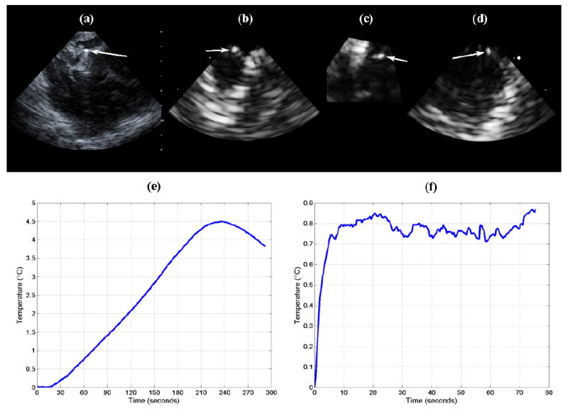
(a) AcuNav image of thermocouple (arrow) placed at 1 cm depth in cerebrum. (b,c,d) RT3D coronal, axial, and sagittal images, respectively, of inserted thermocouple (arrows), acquired with dual-mode catheter. (e) Temperature rise achieved using the AcuNav (transducer self-heating and conduction). (f) Temperature rise achieved by driving the dual-mode catheter's linear array elements as a single channel (unfocused) with an RF power amplifier.
After turning off power, the thermocouple recorded a slow decline in temperature, while the probe itself remained warm. The casing around the transducer had melted and deformed, and the probe could no longer acquire images, indicating that the measured heating was due to energy dissipation within the transducer and conduction through the tissue, rather than ultrasound absorption at the focus. Comparison of the slow heating rate (0.020°C/sec) with those of our in vitro ultrasound hyperthermia experiments (0.164-0.509°C/sec) reinforces this determination.
For the dual-mode catheter, we had decided that driving the linear array elements as a single channel (unfocused) with an external, 25-Watt power amplifier was preferable to using the Volumetrics scanner at high power settings that could potentially harm to its internal electronics. Here the thermocouple was aligned with one side of the linear array at a depth of 0.5 cm, where we expected maximal heating according to our simulations (see Figure 3e). Figure 12b, 12c, and 12d show simultaneous coronal, axial, and sagittal planes of the inserted thermocouple. 3D scanning with the matrix array was paused as thermocouple monitoring was activated and the power amplifier turned on to drive the linear array at 4.6 MHz. The measured temperature rise was just over 0.85°C (see Figure 12f); however, it was found later that the transmit efficiency of the linear array elements had been considerably weakened before and/or during the experiment, indicating that this measurement did not give the maximum possible temperature rise achievable by a dual-mode probe of this design. For this experiment, because we did not exceed 2.0°C of heating, the maximum heating rate (0.146°C/sec) was calculated by dividing by the amount of time taken to achieve the initial 0.685°C of the total temperature rise. This datum was in agreement with our in vitro heating rate measurements.
Summary and Discussion
We successfully created a temperature rise of 5°C in excised pork muscle using the Volumetrics RT3D scanner and customized, channel-specific impedance matching circuits with a 50 channel linear array, demonstrating that hyperthermia might be achievable in brain tissue using catheter arrays. An integrated matrix and linear array catheter transducer prototype was designed and fabricated. When compared to a Siemens AcuNav probe, this dual-mode catheter device exhibited satisfactory RT3D image quality, and it created a 3.5°C temperature rise in tissue-mimicking material at a depth of 2 cm, without using electrical impedance matching circuits. We believe that achieving a higher element yield and adding matching circuits to maximize power output efficiency would make a 4.0°C or greater temperature rise possible using the Volumetrics scanner with this array design.
To our knowledge, we have shown the first intracranial ultrasound images in the brain using catheter probes. In an in vivo canine model, the AcuNav and dual-mode prototype each were placed in the superior sagittal venous sinus to image the brain volume and attempt to create hyperthermia. The higher sensitivity and Doppler resolution of the AcuNav was apparent in 2D scans of cerebral gyri and sulci and of an internal carotid artery; these images demonstrate the immediate clinical imaging potential of intracranial catheters. The dual-mode catheter prototype interrogated a 3D pyramidal volume in real-time, which made it easier to recognize structures within the cranial cavity. The lateral ventricles were easily distinguishable in echo images, and injection of an agitated saline bolus for vessel contrast allowed visualization of the Circle of Willis and several connecting arteries.
The AcuNav was able to create a temperature rise of 4.5°C in canine brain tissue, but it was evident that this was primarily, if not exclusively, due to transducer self-heating and the resulting heat conduction throughout the tissue volume, not absorption of energy from ultrasound waves. This illustrates the importance of considering the conduction of internal heat away from the transducer elements when designing a dual-mode device: we suspect that the polymer casing encapsulating the AcuNav may have been effectively trapping thermal energy and exacerbating the probe's self-heating.
The dual-mode prototype was able to create an in vivo temperature rise less than one degree Celsius by driving the linear array elements as a single channel at 4.6 MHz using a 25-Watt power amplifier. It was discovered that these elements were transmitting very inefficiently, and their performance had been degraded by extensive use during water tank experiments, therefore this result is not conclusive. The maximum heating rate for the dual-mode prototype in vivo was comparable to the in vitro measurement, which indicates that the heating was due to ultrasound absorption and suggests that a 4°C in vivo temperature rise may be achievable with this probe design. Further testing is needed to determine the optimal tissue heating method (focused or unfocused beam) and transmit circuitry settings, and the addition of matching circuits to maximize power output efficiency should enhance the deposition of thermal energy as well.
As a whole, the results from these experiments, in particular the in vivo RT3D images and measured in vitro temperature rises, lead us to believe that the development of an intracranial ultrasound catheter combining RT3D imaging and hyperthermia capability is feasible. In addition to attaining a higher element yield, building electrical impedance matching circuits, and optimizing the driving circuitry, the catheter itself must be built to manage the curves it must make through the vasculature for the intended, minimally-invasive procedure (see Figure 1). This will require a smaller, more flexible catheter for a next-generation device, perhaps similar to the 4.8 Fr design previously described by Light and Smith 40 for 3D intravascular imaging.
In our long term plan, a brain tumor will be localized by CT or MR imaging. Fluoroscopic angiography/venography will be used to guide the 3D ultrasound catheter retrograde from the jugular vein to the dural venous sinuses so that the catheter is adjacent to or in close proximity to the tumor. A microbubble or liposomal agent molecularly targeted to the tumor will be administered via intravenous injection. The dual-mode catheter will produce RT3D ultrasound images with 3D color Doppler of the lesion, and an ultrasound hyperthermia beam will sufficiently warm the given agent, triggering the release of a chemotherapeutic drug at the tumor site.
Acknowledgments
The authors would like to thank Ellen Dixon-Tulloch and Stephen J. Hsu for their assistance. This research was supported by a 2008 Chandran Family Foundation Research Award, and NIH grant EB001040.
References
- 1.ACS. Cancer Facts & Figures 2008. American Cancer Society; 2008. [Google Scholar]
- 2.CBTRUS. Statistical Report: Primary Brain Tumors in the United States, 2000-2004. Central Brain Tumor Registry of the United States; 2008. [Google Scholar]
- 3.Kleihues P, Cavenee WK, International Agency for Research on Cancer., International Society of Neuropathology., International Academy of Pathology., Preuss Foundation for Brain Tumor Research . Pathology and genetics of tumours of the nervous system. IARC Press; 2000. [Google Scholar]
- 4.Mareel M. Anti-Invasive Brain Tumor Therapy: General Aspects and Future Strategies. In: Mikkelsen T, editor. Brain Tumor Invasion: Biological, Clinical, and Therapeutic Considerations. Wiley-Liss; 1998. [Google Scholar]
- 5.Prados MD. Systemic Chemotherapy. In: Bernstein M, Berger MS, editors. Neuro-oncology: The Essentials. Thieme Medical Publishers; 2000. [Google Scholar]
- 6.Lesniak MS. Targeting Drugs to Tumors of the Central Nervous System. In: Ali-Osman F, editor. Brain Tumors. Humana Press; 2005. [Google Scholar]
- 7.Kroll RA, Neuwelt EA. Outwitting the blood-brain barrier for therapeutic purposes: Osmotic opening and other means. Neurosurgery. 1998;42:1083–1099. doi: 10.1097/00006123-199805000-00082. [DOI] [PubMed] [Google Scholar]
- 8.Zunkeler B, Carson RE, Olson J, Blasberg RG, DeVroom H, Lutz RJ, Saris SC, Wright DC, Kammerer W, Patronas NJ, Dedrick RL, Herscovitch P, Oldfield EH. Quantification and pharmacokinetics of blood-brain barrier disruption in humans. Journal of Neurosurgery. 1996;85:1056–1065. doi: 10.3171/jns.1996.85.6.1056. [DOI] [PubMed] [Google Scholar]
- 9.Mesiwala AH, Farrell L, Wenzel HJ, Silbergeld DL, Crum LA, Winn HR, Mourad PD. High-intensity focused ultrasound selectively disrupts the blood-brain barrier in vivo. Ultrasound in Medicine and Biology. 2002;28:389–400. doi: 10.1016/s0301-5629(01)00521-x. [DOI] [PubMed] [Google Scholar]
- 10.Choi JJ, Pernot M, Small SA, Konofagou EE. Noninvasive, transcranial and localized opening of the blood-brain barrier using focused ultrasound in mice. Ultrasound in Medicine and Biology. 2007;33:95–104. doi: 10.1016/j.ultrasmedbio.2006.07.018. [DOI] [PubMed] [Google Scholar]
- 11.Hynynen K, McDannold N, Vykhodtseva N, Jolesz FA. Noninvasive MR imaging-guided focal opening of the blood-brain barrier in rabbits. Radiology. 2001;220:640–646. doi: 10.1148/radiol.2202001804. [DOI] [PubMed] [Google Scholar]
- 12.McDannold N, Vykhodtseva N, Hynynen K. Use of ultrasound pulses combined with Definity for targeted blood-brain barrier disruption: a feasibility study. Ultrasound Med Biol. 2007;33:584–590. doi: 10.1016/j.ultrasmedbio.2006.10.004. [DOI] [PMC free article] [PubMed] [Google Scholar]
- 13.McDannold N, Vykhodtseva N, Hynynen K. Blood-brain barrier disruption induced by focused ultrasound and circulating preformed microbubbles appears to be characterized by the mechanical index. Ultrasound Med Biol. 2008;34:834–840. doi: 10.1016/j.ultrasmedbio.2007.10.016. [DOI] [PMC free article] [PubMed] [Google Scholar]
- 14.Vykhodtseva N, McDannold N, Hynynen K. Progress and problems in the application of focused ultrasound for blood-brain barrier disruption. Ultrasonics. 2008;48:279–296. doi: 10.1016/j.ultras.2008.04.004. [DOI] [PMC free article] [PubMed] [Google Scholar]
- 15.Cho CW, Liu Y, Cobb WN, Henthorn TK, Lillehei K, Christians U, Ng KY. Ultrasound-induced mild hyperthermia as a novel approach to increase drug uptake in brain microvessel endothelial cells. Pharm Res. 2002;19:1123–1129. doi: 10.1023/a:1019837923906. [DOI] [PubMed] [Google Scholar]
- 16.Aubry JF, Tanter M, Pernot M, Thomas JL, Fink M. Experimental demonstration of noninvasive transskull adaptive focusing based on prior computed tomography scans. J Acoust Soc Am. 2003;113:84–93. doi: 10.1121/1.1529663. [DOI] [PubMed] [Google Scholar]
- 17.Guthkelch AN, Carter LP, Cassady JR, Hynynen KH, Iacono RP, Johnson PC, Obbens EAMT, Roemer RB, Seeger JF, Shimm DS, Stea B. Treatment of Malignant Brain-Tumors with Focused Ultrasound Hyperthermia and Radiation - Results of a Phase-I Trial. Journal of Neuro-Oncology. 1991;10:271–284. doi: 10.1007/BF00177540. [DOI] [PubMed] [Google Scholar]
- 18.Hynynen K, Jolesz FA. Demonstration of potential noninvasive ultrasound brain therapy through an intact skull. Ultrasound in Medicine and Biology. 1998;24:275–283. doi: 10.1016/s0301-5629(97)00269-x. [DOI] [PubMed] [Google Scholar]
- 19.Hynynen K, Clement GT, McDannold N, Vykhodtseva N, King R, White PJ, Vitek S, Jolesz FA. 500-element ultrasound phased array system for noninvasive focal surgery of the brain: a preliminary rabbit study with ex vivo human skulls. Magn Reson Med. 2004;52:100–107. doi: 10.1002/mrm.20118. [DOI] [PubMed] [Google Scholar]
- 20.Connors JJ, Wojak JC. Interventional neuroradiology : strategies and practical techniques. Saunders; 1999. [Google Scholar]
- 21.Morris P. Interventional and endovascular therapy of the nervous system : a practice guide. Springer; 2002. [Google Scholar]
- 22.Novak Z, Coldwell DM, Brega KE. Selective infusion of urokinase and thrombectomy in the treatment of acute cerebral sinus thrombosis. American Journal of Neuroradiology. 2000;21:143–145. [PMC free article] [PubMed] [Google Scholar]
- 23.Chow K, Gobin YP, Saver J, Kidwell C, Dong P, Vinuela F. Endovascular treatment of dural sinus thrombosis with rheolytic thrombectomy and intra-arterial thrombolysis. Stroke. 2000;31:1420–1425. doi: 10.1161/01.str.31.6.1420. [DOI] [PubMed] [Google Scholar]
- 24.Dowd CF, Malek AM, Phatouros CC, Hemphill JC. Application of a rheolytic thrombectomy device in the treatment of dural sinus thrombosis: A new technique. American Journal of Neuroradiology. 1999;20:568–570. [PMC free article] [PubMed] [Google Scholar]
- 25.Horowitz M, Purdy P, Unwin H, Carstens G, Greenlee R, Hise J, Kopitnik T, Batjer H, Rollins N, Samson D. Treatment of Dural Sinus Thrombosis Using Selective Catheterization and Urokinase. Annals of Neurology. 1995;38:58–67. doi: 10.1002/ana.410380112. [DOI] [PubMed] [Google Scholar]
- 26.Kuether TA, O'Neill O, Nesbit GM, Barnwell SL. Endovascular treatment of traumatic dural sinus thrombosis: Case report. Neurosurgery. 1998;42:1163–1166. doi: 10.1097/00006123-199805000-00129. [DOI] [PubMed] [Google Scholar]
- 27.Opatowsky MJ, Morris PP, Regan JD, Mewborne JD, Wilson JA. Rapid thrombectomy of superior sagittal sinus and transverse sinus thrombosis with a rheolytic catheter device. American Journal of Neuroradiology. 1999;20:414–417. [PMC free article] [PubMed] [Google Scholar]
- 28.Makin IRS, Mast TD, Faidi W, Runk MM, Barthe PG, Slayton MH. Miniaturized ultrasound arrays for interstitial ablation and imaging. Ultrasound in Medicine and Biology. 2005;31:1539–1550. doi: 10.1016/j.ultrasmedbio.2005.07.008. [DOI] [PubMed] [Google Scholar]
- 29.Pua EC, Qiu YP, Smith SW. Integrated endoscope for real-time 3D ultrasound imaging and hyperthermia: Feasibility study. Ultrasonic Imaging. 2007;29:1–14. doi: 10.1177/016173460702900101. [DOI] [PubMed] [Google Scholar]
- 30.Gentry KL, Smith SW. Integrated catheter for 3-D intracardiac echo cardiography and ultrasound ablation. Ieee Transactions on Ultrasonics Ferroelectrics and Frequency Control. 2004;51:800–808. doi: 10.1109/tuffc.2004.1320739. [DOI] [PubMed] [Google Scholar]
- 31.Wu F, Chen WZ, Bai J, Zou JZ, Wang ZL, Zhu H, Wang ZB. Pathological changes in human malignant carcinoma treated with high-intensity focused ultrasound. Ultrasound in Medicine and Biology. 2001;27:1099–1106. doi: 10.1016/s0301-5629(01)00389-1. [DOI] [PubMed] [Google Scholar]
- 32.Ebbini ES, Yao H, Shrestha A. Dual-mode ultrasound phased arrays for image-guided surgery. Ultrasonic Imaging. 2006;28:65–82. doi: 10.1177/016173460602800201. [DOI] [PubMed] [Google Scholar]
- 33.Bouchoux G, Lafon C, Berriet R, Chapelon JY, Fleury G, Cathignol D. Dual-mode ultrasound transducer for image-guided interstitial thermal therapy. Ultrasound in Medicine and Biology. 2008;34:607–616. doi: 10.1016/j.ultrasmedbio.2007.09.011. [DOI] [PubMed] [Google Scholar]
- 34.Hynynen K. Review of Ultrasound Therapy. 1997 [Google Scholar]
- 35.Barthe PG, Slayton MH, Jaeger PM, Makin IRS, Gallagher LA, Mast TD, Runk MM, Faidi W. Ultrasound Therapy System and Ablation Results Utilizing Miniature Imaging/Therapy Arrays. 2004 [Google Scholar]
- 36.von Ramm OT, Smith SW, Pavy HG. High-Speed Ultrasound Volumetric Imaging-System. 2. Parallel Processing and Image Display. Ieee Transactions on Ultrasonics Ferroelectrics and Frequency Control. 1991;38:109–115. doi: 10.1109/58.68467. [DOI] [PubMed] [Google Scholar]
- 37.Light ED, Mukundan S, Wolf PD, Smith SW. Real-time 3-D intracranial ultrasound with an endoscopic matrix array transducer. Ultrasound in Medicine and Biology. 2007;33:1277–1284. doi: 10.1016/j.ultrasmedbio.2007.02.004. [DOI] [PMC free article] [PubMed] [Google Scholar]
- 38.Smith SW, Pavy HG, von Ramm OT. High-Speed Ultrasound Volumetric Imaging-System. 1. Transducer Design and Beam Steering. Ieee Transactions on Ultrasonics Ferroelectrics and Frequency Control. 1991;38:100–108. doi: 10.1109/58.68466. [DOI] [PubMed] [Google Scholar]
- 39.Lee W, Idriss SF, Wolf PD, Smith SW. A miniaturized catheter 2-D array for real-time, 3-D intracardiac echo cardiography. Ieee Transactions on Ultrasonics Ferroelectrics and Frequency Control. 2004;51:1334–1346. doi: 10.1109/tuffc.2004.1350962. [DOI] [PubMed] [Google Scholar]
- 40.Light ED, Smith SW. Two dimensional arrays for real time 3D intravascular ultrasound. Ultrasonic Imaging. 2004;26:115–128. doi: 10.1177/016173460402600204. [DOI] [PubMed] [Google Scholar]
- 41.Pua EC, Idriss SF, Wolf PD, Smith SW. Real-time 3D transesophageal echocardiography. Ultrasonic Imaging. 2004;26:217–232. doi: 10.1177/016173460402600402. [DOI] [PubMed] [Google Scholar]
- 42.Light ED, Idriss SF, Sullivan KF, Wolf PD, Smith SW. Real-time 3D Laparoscopic ultrasonography. Ultrasonic Imaging. 2005;27:129–144. doi: 10.1177/016173460502700301. [DOI] [PubMed] [Google Scholar]
- 43.Pua EC, Fronheiser MP, Noble JR, Light ED, Wolf PD, Von Allmen D, Smith SW. 3-D ultrasound guidance of surgical robotics: A feasibility study. Ieee Transactions on Ultrasonics Ferroelectrics and Frequency Control. 2006;53:1999–2008. doi: 10.1109/tuffc.2006.140. [DOI] [PubMed] [Google Scholar]
- 44.Ivancevich NM, Pinton GF, Nicoletto HA, Bennett E, Laskowitz DT, Smith SW. Real-Time 3-D Contrast-Enhanced Transcranial Ultrasound and Aberration Correction. Ultrasound in Medicine and Biology. 2008 doi: 10.1016/j.ultrasmedbio.2008.01.015. [DOI] [PMC free article] [PubMed] [Google Scholar]
- 45.Smith SW, Chu K, Idriss SF, Ivancevich NM, Light ED, Wolf PD. Feasibility study: Real-time 3-D ultrasound imaging of the brain. Ultrasound in Medicine and Biology. 2004;30:1365–1371. doi: 10.1016/j.ultrasmedbio.2004.08.012. [DOI] [PubMed] [Google Scholar]
- 46.Blomley MJK, Cooke JC, Unger EC, Monaghan MJ, Cosgrove DO. Science, medicine, and the future - Microbubble contrast agents: a new era in ultrasound. British Medical Journal. 2001;322:1222–1225. doi: 10.1136/bmj.322.7296.1222. [DOI] [PMC free article] [PubMed] [Google Scholar]
- 47.Goldberg BB, Raichlen JS, Forsberg F. Ultrasound contrast agents : basic principles and clinical applications. Dunitz; 2001. [Google Scholar]
- 48.Kheirolomoom A, Dayton PA, Lum AFH, Little E, Paoli EE, Zheng HR, Ferrara KW. Acoustically-active microbubbles conjugated to liposomes: Characterization of a proposed drug delivery vehicle. Journal of Controlled Release. 2007;118:275–284. doi: 10.1016/j.jconrel.2006.12.015. [DOI] [PMC free article] [PubMed] [Google Scholar]
- 49.Bloch SH, Dayton PA, Ferrara KW. Targeted imaging using ultrasound contrast agents. Ieee Engineering in Medicine and Biology Magazine. 2004;23:18–29. doi: 10.1109/memb.2004.1360405. [DOI] [PubMed] [Google Scholar]
- 50.Ponce AM, Vujaskovic Z, Yuan F, Needham D, Dewhirst MW. Hyperthermia mediated liposomal drug delivery. International Journal of Hyperthermia. 2006;22:205–213. doi: 10.1080/02656730600582956. [DOI] [PubMed] [Google Scholar]
- 51.Dayton PA, Ferrara KW. Targeted imaging using ultrasound. Journal of Magnetic Resonance Imaging. 2002;16:362–377. doi: 10.1002/jmri.10173. [DOI] [PubMed] [Google Scholar]
- 52.Gentry KL, Sachedina N, Smith SW. Catheter ultrasound phased-array transducers for thermal ablation: a feasibility study. Ultrason Imaging. 2005;27:89–100. doi: 10.1177/016173460502700203. [DOI] [PubMed] [Google Scholar]
- 53.NEMA. Acoustic Output Measurement Standard For Diagnostic Ultrasound Equipment, Rev 3. 2004 [Google Scholar]
- 54.Fry WJ, Fry RB. Determination of Absolute Sound Levels and Acoustic Absorption Coefficients by Thermocouple Probes - Experiment. Journal of the Acoustical Society of America. 1954;26:311–317. [Google Scholar]
- 55.Hynynen K, Edwards DK. Temperature-Measurements during Ultrasound Hyperthermia. Medical Physics. 1989;16:618–626. doi: 10.1118/1.596364. [DOI] [PubMed] [Google Scholar]
- 56.Jensen JA, Svendsen NB. Calculation of Pressure Fields from Arbitrarily Shaped, Apodized, and Excited Ultrasound Transducers. Ieee Transactions on Ultrasonics Ferroelectrics and Frequency Control. 1992;39:262–267. doi: 10.1109/58.139123. [DOI] [PubMed] [Google Scholar]
- 57.Goss SA, Johnston RL, Dunn F. Comprehensive Compilation of Empirical Ultrasonic Properties of Mammalian-Tissues. Journal of the Acoustical Society of America. 1978;64:423–457. doi: 10.1121/1.382016. [DOI] [PubMed] [Google Scholar]
- 58.Bacon DR, Shaw A. Experimental Validation of Predicted Temperature Rises in Tissue-Mimicking Materials. Physics in Medicine and Biology. 1993;38:1647–1659. doi: 10.1088/0031-9155/38/11/010. [DOI] [PubMed] [Google Scholar]
- 59.Shaw A, Pay NM, Preston RC, Bond AD. Proposed standard thermal test object for medical ultrasound. Ultrasound in Medicine and Biology. 1999;25:121–132. doi: 10.1016/s0301-5629(98)00136-7. [DOI] [PubMed] [Google Scholar]
- 60.Herickhoff CD, Light ED, Mukundan S, Wolf PD, Dixon-Tulloch E, Shih T, Hsu SJ, Smith SW. Intracranial Catheter for Integrated 3D Ultrasound Imaging & Hyperthermia: Feasibility Study. 2007 [Google Scholar]
- 61.Fletcher TF, Hardy RM, Feeney DA. Canine Planar Anatomy. 2006 [Google Scholar]
- 62.Arndt JW, Oyama MA. Agitated saline contrast echocardiography to diagnose a congenital heart defect in a dog. J Vet Cardiol. 2008;10:129–132. doi: 10.1016/j.jvc.2008.03.004. [DOI] [PubMed] [Google Scholar]
- 63.Miselis RR. Neuroscience Laboratory : Laboratory 2-3 : Gross Brain and Spinal Cord. 2006 [Google Scholar]


