Abstract
In this paper, we present a new computationally efficient numerical scheme for the minimizing flow approach for optimal mass transport (OMT) with applications to non-rigid 3D image registration. The approach utilizes all of the gray-scale data in both images, and the optimal mapping from image A to image B is the inverse of the optimal mapping from B to A. Further, no landmarks need to be specified, and the minimizer of the distance functional involved is unique. Our implementation also employs multigrid, and parallel methodologies on a consumer graphics processing unit (GPU) for fast computation. Although computing the optimal map has been shown to be computationally expensive in the past, we show that our approach is orders of magnitude faster then previous work and is capable of finding transport maps with optimality measures (mean curl) previously unattainable by other works (which directly influences the accuracy of registration). We give results where the algorithm was used to compute non-rigid registrations of 3D synthetic data as well as intra-patient pre-operative and post-operative 3D brain MRI datasets.
Keywords: Non-rigid registration, Optimal mass transport, Monge–Kantorovich, Multigrid, Variational methods, GPU
1. Introduction
Image registration is amongst the most common image processing tasks in medical image analysis. Registration is the process of establishing a common geometric reference frame between two or more image data sets and is necessary in order to compare or integrate image data obtained at different times or using different imaging modalities. A vast amount of literature exists on image registration techniques and we refer the reader to Maintz and Viergever (1998), Brown (1992), Goshtasby (2005), Hajnal and Hawkes (2001) for an overview of this field.
Broadly speaking, image registration techniques can be classified as either “rigid” or “non-rigid”. Rigid registration is usually performed when the images are assumed to be of objects that simply need to be rotated and translated with respect to one another to achieve correspondence. Non-rigid registration on the other hand is used when either through biological differences or image acquisition or both, correspondence between structures in two images cannot be achieved without some localized stretching of the images (Crum et al., 2004). In contrast to rigid registration techniques, non-rigid registration techniques are still the subject of significant ongoing research activity. In this paper, we approach the task of non-rigid registration by treating it as an optimal mass transport problem. As with other registration techniques, the computational burden associated with this problem is high. We propose a multi-resolution approach for the solution of this problem on the GPU to alleviate this difficulty.
The optimal mass transport problem was first formulated by a French mathematician Gasper Monge in 1781, and was given a modern formulation in the work of Kantorovich and, therefore, is now known as the Monge–Kantorovich problem (Kantorovich, 1948). The original problem concerned finding the optimal way to move a pile of soil from one site to another in the sense of minimal transportation cost. Hence, the Kantorovich–Wasserstein distance is also commonly referred to as the earth mover’s distance (EMD). More recently, optimal mass transport has found applications in medical image registration problems (Haker et al., 2004, 2001). Although there have been a number of algorithms in the literature for computing an optimal mass transport, the method proposed in Haker et al. (2004, 2001) computes the optimal warp from a first order partial differential equation, which is a computational improvement over earlier proposed higher order methods and computationally complex discrete methods based on linear programming. However, at large grid sizes and especially for 3D registration the computational cost of even this method is significant. Rigorous mathematical details for their algorithm can be found in Angenent et al. (2003).
Though computationally expensive, the OMT method has a number of distinguishing characteristics: (1) it is a parameter free method and no landmarks need be specified, (2) it is symmetrical (the mapping from image A to image B is the inverse of the mapping from B to A), (3) its solution is unique (no local minima), (4) it can register images where brightness constancy is an invalid assumption, and (5) OMT is specifically designed to take into account changes in densities that result from changes in area or volume.
In the present paper, we extend our previous work (Rehman and Tannenbaum, 2007) and implement the more general formulation of the OMT problem for 3D non-rigid registration based on multi-resolution techniques and using the parallel architecture of the GPU. Although multi-resolution methods have served as critical pieces of registration algorithms in the past, it had yet to be shown that the optimal mass transport problem could be solved in the same manner. Our experimental results show that this is indeed the case, a result which has implications for many fields beyond imaging due to the ubiquitous nature of the OMT problem. We also show that the PDE-based solution to the OMT problem is greatly enhanced by our approach to such an extent that it becomes practical for use on large 3D datasets both in terms of speed and accuracy. Overall, these results show that OMT-based image registration is practical on medical imagery and, thus, merits further investigation as an elastic registration technique without the need of smoothness priors or brightness constancy assumptions.
The rest of the paper is organized as follows. In Section 2 we review the mathematical formulation of the problem and show how to obtain a descent direction. In Section 3 we discuss the discretization and the solution of the discrete problem using multi-resolution, multigrid methods implemented on the GPU. In Section 4 we present the results of applying our algorithm to synthetic as well as MRI brain datasets. Finally, in Section 5 we summarize our work.
2. Optimal mass transport for registration
2.1. Formulation of the problem
We model the registration of images as an optimal mass transport problem. Accordingly, the solution to the problem is an optimal mapping û (in some sense) between two densities μ0 > 0 and μ1 > 0 (Kantorovich, 1948). If we now define d as the dimension of the image domain, det(·) as the determinant, u as a mapping from Ω → Ω with Ω a subdomain of ℝd, and represent by ρ(·,·) : Ω × Ω → ℝ+ a function of distance between two points in Ω, then the problem can be formalized as
| (2.1) |
We refer to the constraint c(u) = 0 as the mass preserving (MP) property.
For the remainder of this paper, we take ρ(·,·) to be the squared distance function ρ(u(x), x) = ║u(x) − x║2. Even for the simple L2-norm, (2.1) defines a highly non-linear optimization problem. While there exists a large body of literature which deals with the analysis of the problem, such as (Ambrosio, 2000; Evans, 1989), only a smaller number of papers discuss efficient numerical solutions for the problem. Benamou and Brenier estimate û by relating Eq. (2.1) to the minimization of a certain kinetic energy functional with a space-time transport partial differential equation (PDE) constraint (Benamou and Brenier, 2003). Their approach not only estimates the optimal mapping but also provides the transportation path between the densities. A computationally faster solution to (2.1) was proposed in Haker et al. (2001), Angenent et al. (2003) and Haker et al. (2004). Their algorithm directly estimates û by first computing a transformation u0 that fulfills the MP property. Afterwards, the algorithm improves u0 by concatenating the mapping with the transformation
| (2.2) |
We refer to the second equation in (2.2) as the c̃ constraint. This means that s ∈ 𝒮 is an MP mapping from μ0 to itself. The authors in Angenent et al. (2003) and Haker et al. (2004) show that ŝ can be estimated via a steepest descent flow. To register 2D MRIs, they implement the method using forward Euler equation scheme for time stepping and a simple finite difference discretization of the spatial derivatives. The approach, however, does not enforce the MP constraint at each step of the numerical algorithm, so that the final solution generally does not fulfill the MP property. In addition, steepest descent is very slow in estimating the solution to Eq. (2.2). For these reasons it would be very challenging to efficiently register 3D medical images with this approach. To overcome this hurdle, this paper describes a faster numerical solution to Eq. (2.2) that enforces the MP constraint.
Unlike Angenent et al. (2003) and Haker et al. (2004), we solve the optimization problem via an approach where we choose a direction other than steepest descent and show that it converges faster (see Section 2.2). Furthermore, we derive a numerical approach that uses a consistent conservative discretization method and enforces the MP constraint at each update of the solution (Section 3).
We end this section with the comment that our approach most closely relates to those registration approaches based on fluid mechanics. The optimal warping map of the L2 Monge–Kantorovich equation may be regarded as the velocity vector field which minimizes a standard energy integral subject an Euler continuity equation constraint (Benamou and Brenier, 2003). In particular, in the fluid mechanics framework, this means that the optimal Monge–Kantorovich solution is given as a potential flow.
2.2. Obtaining the descent direction
We now quickly review the derivation presented in Angenent et al. (2003) and Haker et al. (2004) but within a variational framework.
Assuming that the MP constraint manifold (2.2) is valid we take a perturbation in s which stays on the MP constraint manifold. This leads to
This expression can be simplified as long as the constraint is valid. Since det(∇u) > 0 we can divide, and rearranging we have
Defining δζ = μ0δs(s−1), we see that
Next, looking at u = u0(s−1), we can write u(s) = u0 which implies that
or
Using the definition of δζ we obtain that as long as the constraint is valid and for u(s) = u0, we have
| (2.3a) |
| (2.3b) |
Letting M denote the objective function in (2.2), it can be shown that
| (2.3c) |
In the original papers (Haker et al., 2001; Angenent et al., 2003; Haker et al., 2004), it is suggested to use the Helmholtz decomposition in order to obtain a descent direction. Here we employ a different approach. First, we note that the divergence constraint can be eliminated by selecting
and thus to reduce the objective function M we need to obtain a direction that yields a negative δM, that is we seek a direction, δη such that
Using Gauss theorem we obtain that
and therefore the steepest descent direction is given by
which leads to the update
and finally to the steepest descent direction in u
or, in symmetric form
| (2.3d) |
The reason that this form is useful is because it can help to further understand the behavior of the system. The elliptic operator −∇ × ∇ × is a negative operator thus, the equation can be thought of as a parabolic PDE as long as all the eigenvalues of ∇u have positive real parts. If at some point this condition is violated (negative real parts), then we obtain a backward parabolic equation which is ill-posed. This point must be carefully considered for the numerical method to be used.
Using the above decomposition a family of different directions may be obtained. Note that in order to reduce the objective ∫Ω ∇ × u · ηdx, any vector field of the form
can be used. For example, a choice that leads to a similar method to the one derived in the original works (Angenent et al., 2003; Haker et al., 2004) in 2D is A = −Δ−1 which leads to the update
| (2.3e) |
It is also easy to see that the flow (2.3e) is valid in 3D. Moreover, using Fourier analysis it is easy to verify that given a smooth u the second formulation (2.3e) leads to a more stable method that should converge faster compared with the first formulation (2.3d), because the operator ∇ × Δ−1 ∇ × is compact while the ∇ × ∇ × operator is unbounded (Trottenberg et al., 2001a). Thus, (2.3e) will not in general prefer high or low frequencies. In the next section, we therefore derive a numerical method for (2.3e) rather than for (2.3d).
3. Implementation
In this section we derive an efficient numerical method for the solution of the flow. The method has four main components:
pre-processing of input volume data.
conservative discretization of Eq. (2.3e).
a criterion to choose the step size.
a method to correct steps that drift away from the constraint. (2.2).
3.1. Pre-processing input data
In context of image registration applications the input data to our algorithm is the source and target volumes that need to be registered. For all the examples presented in this paper we model the mass density for a voxel as the image intensity. However, it can also be alternatively defined as any scalar field that is related to the underlying physical model. This property can be exploited for non-rigid registration of multi-modality data as well, where sufficient anatomical correspondence exists between the source and target datasets. This will be further studied in future work. In order for the notion of mass transport to hold it is necessary that both volumes have same total mass. This is ensured by normalizing the image intensities by the respective sum of all intensity values in each volume. The normalized data is then scaled by a common factor to avoid numerical instability due to very small values. Another step in the pre-processing of input data is the addition of a small mass in the background regions where there the intensity values are zero in order to avoid a divide-by-zero while solving Eq. (2.3e). Another step necessary in context of Brain MRI registration is dealing with the inherent anisotropic nature of the data. We pre-process all brain MRI data by interpolating and re-sampling to isotropic voxels.
3.2. Conservative discretization
The applications we have in mind derive from medical imaging where images are discretized on a regular grid. We therefore construct our discretization based on a finite volume/difference approach. To derive and analyze our discretization we introduce a new variable δp = Δ−1 ∇ × u and rewrite (2.3e) as
| (3.7) |
In order for the discrete system to be well posed we need consistent discretizations for Δ, ∇u and ∇ × u. There are a number of possible discretizations that lead to a well-posed system.
We divide Ω into n1 × … × nd cells, each of size h1 × … × hd where d is the dimension of the problem. We discretize all the components of u at the nodes of each cell to obtain d grid functions û1, … ûd. Since δp is connected to u by the curl operator, we employ a staggered grid and place δp at cell centers. To approximate ∇u at each node, we use long differences. For example, in 2D, assuming h1 = h2 = h, we have
Thus, in 3D, the discretized (1,1) block in (3.7) is a matrix of the form
| (3.8) |
where Dj is a matrix of long differences in the jth direction. Assuming u is sufficiently smooth it can be shown that upon a consistent discretization of the Laplacian the system (3.7) is invertible and that the overall (discrete) problem is well-posed. To obtain a consistent discretization of the Laplacian we use a standard discretization (5 point stencil in 2D and 7 point stencil in 3D) with Dirichlet boundary conditions.
Finally, we need to discretize the curl of u. Here we use short differences in one direction averaged in the other direction to obtain a cell center, second order accurate approximation of ∇ × u. For example, in 2D we obtain
| (3.9) |
where C denotes the curl matrix.
3.3. Computation of a step
The computation of each step requires two parts. Firstly, the solution of (3.7) and secondly, a way to determine if it is an acceptable step. The solution of the system (3.7) is straightforward. Any fast Poisson solver can be used for the task. Here we have used a standard multigrid method with weighted Jacobi smoothing (Trottenberg et al., 2001b), bilinear prolongation and its adjoint as a restriction (Trottenberg et al., 2001c).
The validity of the update is determined using the following procedure. Assume that at iteration n we have ûn as an approximation to u and that we computed δû. The update is then performed using,
| (3.10) |
where 𝒫 is an orthogonal projection discussed in Section 3.4 below that projects ûn + αδû into the mass preserving manifold. The step size α is then chosen such that the objective function is decreased and that the real part of the eigenvalues of (∇hû) is positive. The entire procedure is outlined in Algorithm 1.
Algorithm 1
Solution of OMT:û ← OMTsol(μ0, μ1);
| Use μ0 and μ1 to compute a mass preserving u0 |
| while true do |
| Solve (3.7) for δû |
| line search: set α = 1 |
| while true do |
| ûn+1 = 𝒫 (ûn + αδû) |
| if ║ûn+1 − x║μ0 < ║ûn − x║μ0 and Re(λ(∇hun+1)) > 0 then |
| Break |
| end if |
| α ⇐ α/2 |
| end while |
| end while |
3.4. Orthogonal projection into the mass preserving constraint
Assume that we have computed a mass preserving mapping ûn, and that we have updated it to obtain vn = ûn + αδû. It should be noted that an infinitesimal δû does not guarantee mass preservation. Furthermore, we aim to take large steps in δû, and therefore the MP constraint is likely to be invalid. To correct for this we use orthogonal projection. The goal is to compute a vector field δv such that c(v + δv) = 0. Obviously, δv is non-unique and therefore we seek a minimum norm solution that is we seek δv such that
subject to
It is easy to verify that a correction for δv can be obtained by solving the system (Nocedal and Wright, 1999) The system can be thought as an elliptic system of equations. The system is solved using preconditioned conjugate gradient with an incomplete Cholesky preconditioner.
3.5. 3D multigrid Laplacian inversion
We inverted the Laplacian (a key component of the OMT algorithm) using a 3D multigrid solver. The multigrid idea is very fundamental. It takes advantage of the smoothing properties of the classical iteration methods at high frequencies (Jacobi, Gauss Siedel, SOR, etc.) and the error smoothing at low frequencies by restriction to coarse grids. The essential multigrid principle is to approximate the smooth (low frequency) part of the error on coarser grids. The non-smooth or rough part is reduced with a small number of iterations with a basic iterative method on the fine grid.
The basic components of multigrid algorithm are discretization, intergrid transfer operators (interpolation and restriction), a relaxation scheme and the iterative cycling structure. We used an explicit finite difference scheme for approximating the 3D Poisson equation. This approach uses a 19-point formula on the uniform cubic grid. Relaxation was performed using a parallelizable four-color Gauss-Seidel relaxation scheme. This increases robustness and efficiency and is especially suited for the implementation on the GPU. We used a trilinear interpolation operator for transferring the coarse grid correction to fine grids. The residual restriction operator for projecting residual from the fine to coarse grids is the full-weighting scheme. A multigrid V(2,2)-cycle algorithm was used to iterate for the solution (residual max norm ≈ 10−5). The interested reader is referred to Gupta and Zhang (2000); Briggs et al. (2000); Trottenberg et al. (2001c) for complete details on implementation of the multigrid method.
3.6. GPU implementation
An advantage of our solution to the OMT problem is that it is particularly well-suited for implementation on parallel computing architectures. Over the past few years, it has been shown that graphics processing units (GPUs; now standard in most consumer-level computers), which are naturally massively parallel, are well suited for these types of parallelizable problems (Bolz et al., 2003; Nolan et al., 2003).
A GPU is a highly parallel computing device designed for the task of graphics rendering. However, the GPU has evolved in recent years to become a more general processor, allowing users to flexibly program certain aspects of the GPU to facilitate sophisticated graphics effects and even scientific applications. In general, the GPU has become a powerful device for the execution of data-parallel, arithmetic (versus memory) intensive applications in which the same operations are carried out on many elements of data in parallel. Example applications include the iterative solution of PDE’s, video processing, machine learning, and 3D medical imaging.
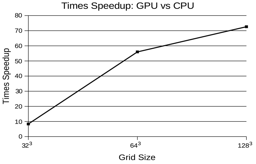
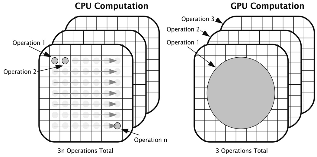
Taking advantage of the benefits a parallel approach has to offer our problem, we implemented our OMT multigrid algorithm on the GPU. The GPU’s advantage over the CPU in this sense is that while the CPU can execute only one or two threads of computation at a time, the GPU can execute over two orders of magnitude more. Thus, instead of sequentially computing updates on data grids one element at a time, the GPU computes updates on entire grids on each render pass, significantly improving performance (Fig. 3). For instance, on a modest Dual Xeon 1.6Ghz machine with an nVidia GeForce 8800 GX GPU (3DMark score of 7200), improvements in speed over our CPU OMT implementation reached 4826 percent on a 1283 volume data where it converges in just 15 minutes. Presently available GPUs only allow single precision computations, however, this did not affect the stability of the OMT algorithm.
Fig. 3.
The GPU realizes an increasing advantage in solving the OMT problem over the CPU as grid size increases up to 1283 sized grids.
The OMT algorithm is implemented on the GPU as a series of kernel operations: arithmetic computations performed component-wise over large grids of data. An example of such an operation is the restriction operator utilized in the multigrid algorithm to down-sample data; each element of an input data grid is convolved and re-sampled to a lower resolution grid. The data flow and sequence of kernel applications involved in the OMT solver are given in Fig. 1. All kernels are written in Cg in conjuction with the OpenGL/fragment shader paradigm for GPU computing as described in Pharr (2005). Fig. 2
Fig. 1.
Outline of processing for the OMT solver conducted on the GPU. Processing occurs in two major phases: evolution of the map from source to target volumes and time step adjustment. Each gray rectangle represents one Cg kernel executed on the GPU. Arrows indicate the flow of data volumes through the Cg kernels. The entire process in the figure, above is repeated left to right until convergence.
Fig. 2.
CPU versus GPU solution of PDEs: While the CPU computes updates on data grids one element at a time, the GPU is capable of updating entire grids in one pass due to their massively parallel architecture.
4. Results
We illustrate our registration method using both synthetic and real examples. We start by recovering a known deformation field that relates two images. We then register two synthetically generated spherical volumes and conclude by giving a real example of 3D Brain MRI image registration.
4.1. Synthetic examples
A synthetic example can easily be constructed to test the convergence of our algorithm. We used the standard MATLAB 3D MRI dataset for this experiment. Since, the optimal map u can be defined as the gradient of a convex function ϕ (Angenent et al., 2003). We define one such function as,
where c, σ1, σ2 and σ3 are parameters chosen to create a unique deformation field. Differentiating ϕ with respect to x = (x1, x2, x3), we obtain u = (u1, u2, u3),
where,
We then apply this deformation field u to μ1 (x1, x2, x3) (MAT-LAB MRI data) to obtain μ0 (x1, x2, x3) as per the following relationship:
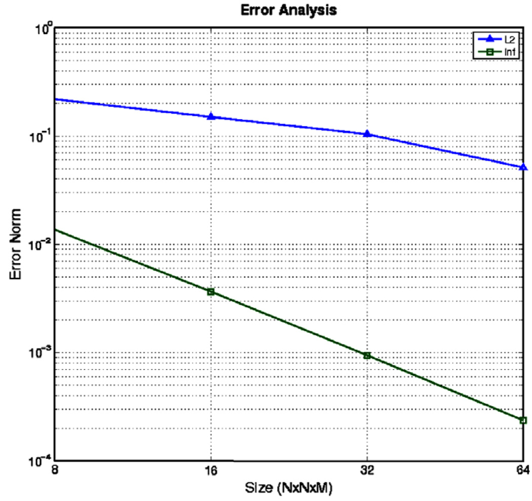
We then input the μ0 and μ1 pair into our solver to find the transformation u. We terminated our algorithm after 100 iterations or when the curl of the solution was 4 orders of magnitude smaller than its initial size (in the ∞-norm). The algorithm was run with input sizes of 8 × 8 × 8, 16 × 16 × 16, 32 × 32 × 32 and 64 × 64 × 32. The error between the known and computed deformation fields is plotted in Fig. 4 as a function of the grid size which clearly demonstrates quadratic convergence of our method to the true solution as is expected from the discretization error used in our numerical approximations.
Fig. 4. Error Analysis-Known Deformation Example.
L2-norm and ∞-norm of error in calculation of u as a function of grid size.
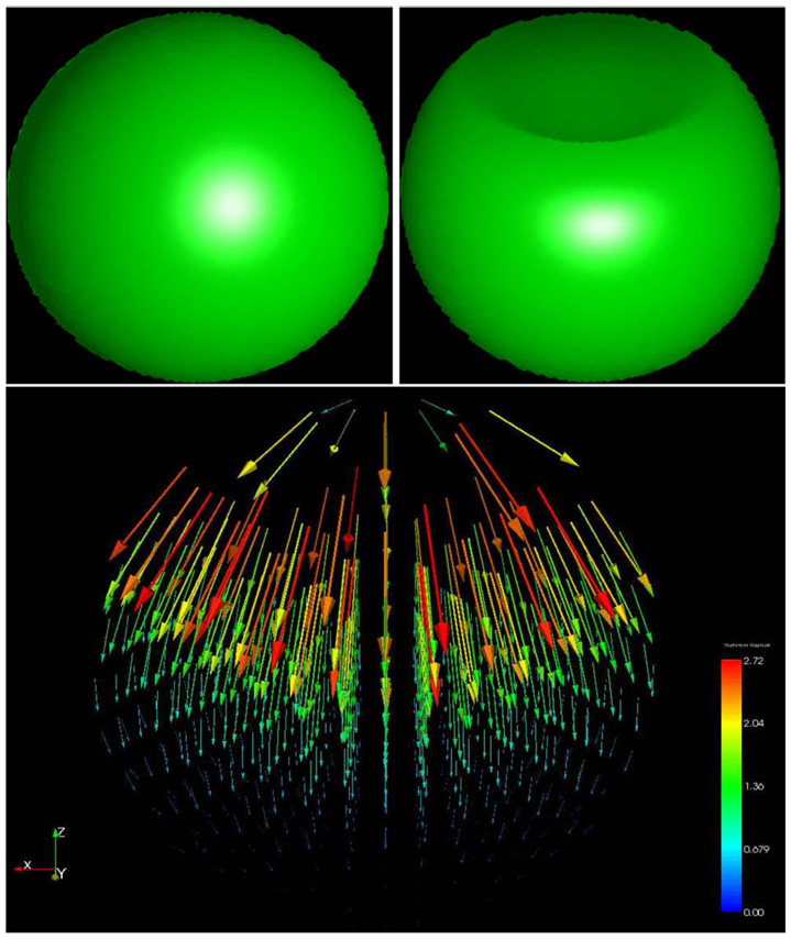
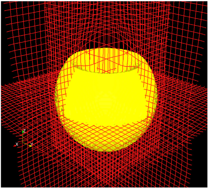
In the second case, we register a synthetically generated 3D sphere (128 × 128 × 128) to a deformed (dented) counterpart; see Fig. 5. It can be clearly seen that our algorithm does a good job in capturing the deformation in the sphere.
Fig. 5. Synthetic Imagery Results.
A sphere is mapped to its deformed counterpart. In the lower image we show the deformation vector field. It is clearly visible that the magnitude of deformation is maximum at the top where the dent is and it decays smoothly inside the sphere (Data size 1283).
4.2. Brain sag registration
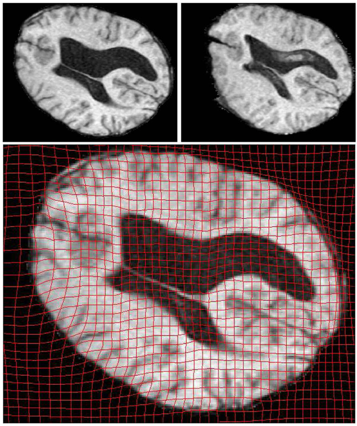
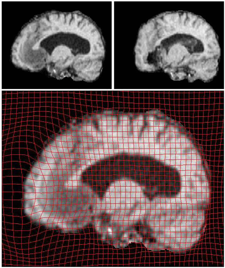
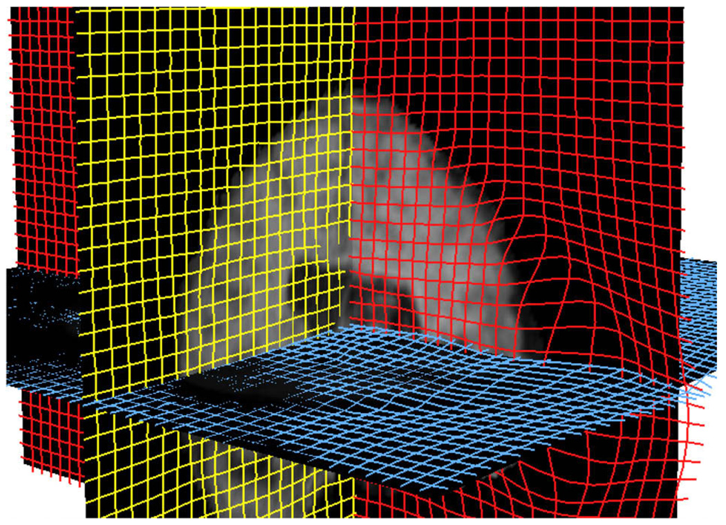
In the third case, we registered two 3D brain MRI datasets. The first data set was pre-operative while the second data set was acquired during surgery (craniotomy and opening of the dura). Both were resampled to 2563 voxels and pre-processed to remove the skull. For clarity we view the 2D deformation grid overlaid on corresponding sagital and coronal slices in Fig. 6 and Fig. 7, respectively.
Fig. 6.
OMT Results viewed on an axial slice. The top row shows corresponding slices from Pre-op(Left) and Post-op(Right) MRI data. The deformation is clearly visible in the anterior part of the brain.
Fig. 7.
OMT Results viewed on a sagital slice. The top row shows corresponding slices from Pre-op(Left) and Post-op(Right) MRI data. Here again the maximum deformation is visible on the anterior part of the brain.
Fig. 8 and Fig. 9 show the respective deformation grids of the above examples in 3D. For each of the above examples the deformation map was computed in fewer than 20 iterations. The curl (optimality metric) was reduced to less than 10−3, indicating convergence. This is a major improvement over the previous methods (Haker et al., 2004; Angenent et al., 2003) where thousands of iterations were required for convergence. Another advantage to our method is the explicit projection to the mass preserving constraint in each iteration which ensures that the calculated mapping always takes us from the source image to the target image.
Fig. 8. Sphere Registration(3D View).
The deformation is visible at the dented region of the sphere. (Data size 1283).
Fig. 9. Brain Sag Registration(3D View).
The brain sag is visible in the anterior portion of the brain. (Data size 2563).
5. Conclusions
In this paper, we presented a computationally efficient method for 3D image registration based on the classical problem of optimal mass transportation implemented in a novel manner.
Many times, global elastic registration methods based on principles from computational fluid dynamics of the type presented in this work are so computationally intensive that they become impractical for realistic problems in medical imaging. However, we have shown that optimal mass transport is, in fact, a viable solution for elastic registration by achieving low run times for typically sized 3D datasets on standard desktop computing platforms. In future work, we will be applying this methodology to other interesting cases as well as extending the results to 3D surfaces (for which the Monge–Kantorovich theory holds).
Acknowledgement
This work was supported in part by grants from NSF, AFOSR, ARO, as well as by a grant from NIH (NAC P41 RR-13218) through Brigham and Women’s Hospital. This work is part of the National Alliance for Medical Image Computing (NAMIC), funded by the National Institutes of Health through the NIH Roadmap for Medical Research, Grant U54 EB005149. Information on the National Centers for Biomedical Computing can be obtained from http://nihroadmap.nih.gov/bioinformatics. The authors were also partially funded by NSF Grants CCF-0728877, CCF-0427094 and DOE Grant DE-FG02-05ER25696. We also want to thank Florin Talos at Surgical Planning Laboratory, Department of Radiology, Brigham & Women’s Hospital, Harvard Medical School, Boston, MA for graciously providing Brain MRI data.
References
- Ambrosio L. Lecture notes on optimal transport problems. Lectures given at Euro Summer School. 2000 July; 2000. URL http://cvgmt.sns.it/papers/amb00a/
- Angenent S, Haker S, Tannenbaum A. Minimizing flows for the Monge–kantorovich problem. SIAM Journal of Mathematical Analysis. 2003;36:61–97. [Google Scholar]
- Benamou JD, Brenier Y. A computational fluid mechanics solution to the Monge–kantorovich mass transfer problem. SIAM Journal of Mathematical Analysis. 2003;35:61–97. [Google Scholar]
- Bolz J, Farmer I, Grinspun E, Schroeder P. Sparse matrix solvers on the GPU: conjugate gradients and multigrid. Proceedings of SIGGRAPH; 2003. pp. 917–924. [Google Scholar]
- Briggs W, Hensen V, McCormick S. A Multigrid Tutorial. SIAM. 2000 [Google Scholar]
- Brown LG. A survey of medical image registration. ACM Computing Surveys. 1992;24:325–376. [Google Scholar]
- Crum W, Hartkens T, Hill D. Non-rigid image registration: theory and practice. British Journal of Radiology. 2004;77:S140–S153. doi: 10.1259/bjr/25329214. (Special Issue) [DOI] [PubMed] [Google Scholar]
- Evans LC. Partial differential equations and Monge–kantorovich transfer. Lecture notes. 1989 URL http://math.berkeley.edu/~evans/Monge-Kantorovich.survey.pdf.
- Goshtasby AA. 2-D and 3-D image registration: for medical, remote sensing, and industrial applications. Hoboken, NJ: John Wiley and Sons; 2005. [Google Scholar]
- Gupta MM, Zhang J. High accuracy multigrid solution of the 3d convection-diffusion equation. Applied Mathematics and Computation. 2000;113:249–274. [Google Scholar]
- Haker S, Tannenbaum A, Kikinis R. Mass preserving mappings and image registration. MICCAI. 2001:120–127. [Google Scholar]
- Haker S, Zhu L, Tannenbaum A, Angenent S. Optimal mass transport for registration and warping. International Journal of Computer Vision. 2004;60(3):225–240. [Google Scholar]
- Hajnal JV, Hawkes DLGH. The Biomedical Engineering Series. Boca Raton, FL: CRC Press; 2001. Medical Image Registration. [Google Scholar]
- Kantorovich LV. On a problem of Monge. Uspekhi Matematicheskikh Nauk. 1948;3:225–226. [Google Scholar]
- Maintz JA, Viergever MA. A survey of medical image registration. Medical Image Analysis. 1998;2:1–57. doi: 10.1016/s1361-8415(01)80026-8. [DOI] [PubMed] [Google Scholar]
- Nocedal J, Wright S. Numerical Optimization. New York: Springer; 1999. Chapter 18; pp. 547–548. [Google Scholar]
- Nolan G, et al. A multigrid solver for boundary value problems using programmable graphics hardware. Proceedings of SIGGRAPH; 2003. pp. 102–111. [Google Scholar]
- Pharr M. GPU Gems. Vol. 2. Addison-Wesley; 2005. [Google Scholar]
- Rehman T, Tannenbaum A. Multigrid optimal mass transport for image registration and morphing. Proceedings of SPIE Conference on Computational Imaging; 2007. p. 649810. [Google Scholar]
- Trottenberg U, Oosterelee C, Schüller A. Multigrid: Academic Press; 2001a. Chapter 4; pp. 102–106. [Google Scholar]
- Trottenberg U, Oosterelee C, Schüller A. Multigrid: Academic Press; 2001b. Chapter 2; p. 30. [Google Scholar]
- Trottenberg U, Oosterelee C, Schüller A. Multigrid: Academic Press; 2001c. [Google Scholar]


