Abstract
In the presence of intrafraction organ motion, target localization uncertainty can greatly hamper the advantage of highly conformal dose techniques such as intensity modulated radiation therapy (IMRT). To minimize the adverse dosimetric effect caused by tumor motion, a real-time knowledge of the tumor position is required throughout the beam delivery process. The recent integration of onboard kV diagnostic imaging together with MV electronic portal imaging devices on linear accelerators can allow for real-time three-dimensional (3D) tumor position monitoring during a treatment delivery. The aim of this study is to demonstrate a near real-time 3D internal fiducial tracking system based on the combined use of kV and MV imaging. A commercially available radiotherapy system equipped with both kV and MV imaging systems was used in this work. A hardware video frame grabber was used to capture both kV and MV video streams simultaneously through independent video channels at 30 frames per second. The fiducial locations were extracted from the kV and MV images using a software tool. The geometric tracking capabilities of the system were evaluated using a pelvic phantom with embedded fiducials placed on a moveable stage. The maximum tracking speed of the kV∕MV system is approximately 9 Hz, which is primarily limited by the frame rate of the MV imager. The geometric accuracy of the system is found to be on the order of less than 1 mm in all three spatial dimensions. The technique requires minimal hardware modification and is potentially useful for image-guided radiation therapy systems.
Keywords: EPID, OBI, marker tracking, 4D radiotherapy
INTRODUCTION
In radiation therapy (RT), delivering a highly conformal dose distribution to a static three-dimensional (3D) target is largely solved by techniques such as intensity modulated radiation therapy (IMRT).1, 2 What remains problematic is how to take into account the dynamic nature of human anatomy, where both inter- and intrafraction organ motion can limit target dose conformity3, 4 and therefore local tumor control.5 Tumor motion can be addressed by increasing the planning target volume (PTV) to include the entire range of motion of the target, however, usually at the cost of irradiating more healthy tissue. Other techniques used to address tumor motion are direct patient intervention through breath-hold techniques6 or the delivery of radiation only when the target is in a known geometric location by the use of gating.7, 8, 9, 10 These techniques transform the problem of targeting a moving tumor into a more easily manageable static treatment case. Ideally, one would like to deliver highly conformal radiation, as in a static IMRT case, to a moving target without beam interruption or patient intervention. Promising candidates in this direction include tumor tracking by moving the radiation source itself11, 12, 13 or the beam defining multileaf collimator.14, 15, 16
To successfully guide a gating or tracking RT delivery system, real-time knowledge of the target geometric location is necessary. Several methods of obtaining the real-time tumor position are available and these can be categorized as being either indirect (surrogate-based) or direct (fiducial∕image) in nature. In general, indirect tumor location methods, such as external skin marker tracking10, 17, 18 or breath monitoring techniques,19 rely on the correlation between external body parameters and the tumor. In reality, the relationship between external parameters and internal organ motion is complex and a large uncertainty may be present in predicting the tumor location based on external signals.20, 21 The unreliable correlation represents one of the weakest links in the quality chain of respiration-gated and four-dimensional (4D) RT. A direct tumor position measurement is highly desirable for therapeutic guidance. In the last decade, a number of direct real-time 3D tumor tracking methods have been implemented, primarily using fluoroscopy22, 23 or magnetic field localization.24 The feasibility of using electronic portal imaging devices (EPID) for real-time tumor targeting has also been explored.25 However, since only a single in-line MV beam was employed, this approach suffers from insufficient information to completely define the 3D coordinates of the embedded fiducials.
With the emergence of linear accelerators (LINACs) equipped with both onboard kV imaging and EPID, the potential exists to obtain the tumor position in real-time during the radiation delivery process through the combined use of the MV treatment beam and kV projection images. In this work we report our implementation of such a real-time 3D tracking system and demonstrate that a spatial accuracy of <1 mm is achievable in tracking fiducials using the proposed technique. The method takes advantage of the kV∕MV imaging devices already mounted on commercially available treatment machines, thus providing an easily implemented method for monitoring intrafractional tumor motion. Since projection data containing two-dimensional target information is obtained using the actual treatment beam, the proposed method only requires the use of one kV source in gaining the other spatial dimension necessary for full 3D target localization. Compared to other fluoroscopic tracking systems, which require the use of two or more additional kV x-ray imaging systems, the technique may offer potential radiation sparing to the patient and overall system cost reductions. With the use of real-time spatial trajectory information of fiducials in the future, it is hoped that uncertainties in intrafraction target localization can be greatly reduced, thus ensuring a more accurate delivery of the planned conformal dose distribution.
MATERIALS AND METHOD
Hardware setup
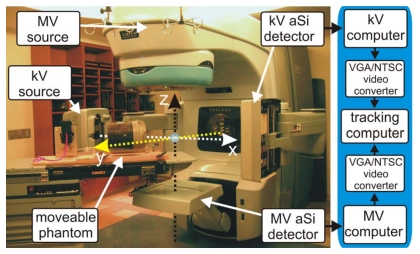
A Varian Trilogy™ system (Varian Medical Systems, Palo Alto, CA) operating in the 6 MV photon mode was used for this study. Images of the MV beam were acquired using an aSi EPID (Portal Vision MV AS-500, Varian Medical Systems, Palo Alto, CA) attached to the LINAC as shown in Fig. 1. The kV imaging was obtained by using the onboard kV imaging system located perpendicular to the treatment beam (Fig. 1). The device consists of a 125 kV x-ray tube together with an aSi flat panel imager (PaxScan 4030CB, Varian Medical Systems, Salt Lake City, UT). Both kV and MV detectors have a pixel width of 0.392 mm and a maximum resolution of 1024×768, corresponding to a 40 cm×30 cm effective area of detection. The maximal frames per second (fps) obtainable from the kV and MV detectors in this work are 15 and 9 Hz, respectively. The kV and MV source detector distances (SDD) are set to 180 and 150 cm, respectively, though in principle this can be varied to a wide variety of distances as allowed by the robotic arms (Fig. 1).
Figure 1.
Varian Trilogy with kV and MV imagers in extended positions. System frame of reference is denoted by dashed arrows. A pelvic phantom, placed on a movable stage, is located on the couch. To the right is displayed the process path used for image acquisition.
kV∕MV image acquisition and marker localization
A dedicated image processing PC was used to process and analyze both kV and MV video streams simultaneously as detailed in Fig. 1. Two channels of a four channel PCI video grabber (ProVideo 149P, ProVideo Co., Taipei Hsien, Taiwan) were used to grab the kV and MV video streams at 30 fps per channel with a resolution of 640×480. A freely available third party software program,26 designed for machine vision prototyping, was used to interface with the capture card and analyze the video. The software contains a large database of common video processing filter modules and allows the user to apply, or remove, various combinations of filters to the video pipeline in real time. In addition, the program allows customized script filters to be created. The following sequence of filters were found to be adequate in detecting the fiducial; (1) a region-of-interest (ROI) filter, (2) pseudocolor filter to convert the grayscale captured image into a color image, (3) a color filter to extract the fiducial color value, (4) a mean filter to average pixel values to reduce noise, (5) a detect blob filter to segment the fiducial from the background, (6) a center-of-mass filter to calculate the central pixel location of the blob, and (7) an in-house written script filter to convert the pixel location to a real-space location from system isocenter.
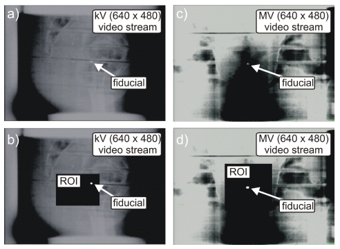
The ROI filter requires the operator to manually enter pixel locations to define a rectangle encompassing the fiducial’s range of motion (Fig. 2). Through a process of visual inspection and identification, the operator must initially define the ROI for both kV and MV video streams. Use of the ROI filter has the benefit of removing unnecessary background pixel information from the image-processing pipeline, thereby increasing computational speed. In the event of a large change in fiducial motion (couch shift or phantom repositioning), the ROI may no longer encompass the entire range of motion of the fiducial, in this case the ROI must be redefined.
Figure 2.
Displayed snap shots of a BB fiducial in a pelvic phantom for the kV and MV video streams before [(a) and (c)] and after [(b) and (d)] applying the fiducial detection algorithm on the selected ROI.
The pseudocolor filter converted the grayscale image to a spectrum of colors ranging from red to blue, with black corresponding to blue and white to red. Thus, metallic fiducials appeared reddish after application of the filter. This allowed for easy detection using a red color filter (step 3). It should be noted, that an intensity based fiducial segmentation can also be performed, however, in this study we found the pseudocolor followed by a color filter technique to be adequate.
The blob filter module was provided by the software package and allows identification of a cluster of pixels, or blob, based on its particular features. By providing features as the size and shape of blobs pertaining to fiducials, the blob filter is able to identify and segment the fiducial from the image even in the presence of a noisy background.
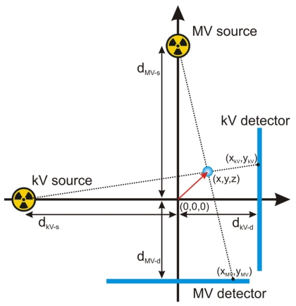
Having detected the fiducial’s center-of-mass, the real-space (x,y,z) marker locations from system isocenter were calculated using the geometric relationships depicted in Fig. 3 and given by the following relations [Eqs. 1, 4]:
| (1) |
| (2) |
| (3) |
| (4) |
Here (x,y,z) corresponds to the marker’s position from system isocenter where the isocenter is defined at 100 cm source axis distance (SAD) and the center of the MV beam. The kV and MV photon source-to-isocenter distances are given by dkV−s and dMV−s, respectively. The isocenter to kV and MV detector distances are given by dkV−d and dMV−d, respectively. The algorithm also takes into account gantry angle (θ) by use of a rotational transform matrix equation to connect the systems frame of reference with that of the laboratory
| (5) |
where (x′,y′,z′) denotes the marker’s coordinates from system isocenter in the laboratory’s frame of reference.
Figure 3.
Geometric sketch detailing variables used for calculation of a marker’s(x,y,z) position from isocenter (0,0,0). The xz plane is shown with the y axis pointing out of the page.
Although the fiducial detection and localization algorithm lowers the processing speed to 15 fps due to processing time, the main bottleneck is found to be the ∼9 fps hardware limitation of the EPID aSi detector. Therefore, the maximum 3D fiducial tracking speed of the system is approximately 9 fps.
kV and MV tracker calibration
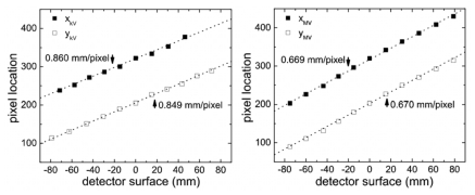
Calibration of the tracking system was necessary in order to convert the detected location of the center-of-mass of the fiducial in the image frame to the real space coordinate of the fiducial in the laboratory frame of reference. The calibration technique used a single 3.0 mm diameter stainless steel ball bearing (BB) fixed near the end of a Styrofoam block-like phantom with a dimension of 600 mm×200 mm×23 mm. The end, not containing the BB, was rigidly mounted to a 3D displacement stage place on the couch, whereas, the other end, extended 500 mm over the couch toward the gantry. This setup allowed images of the BB containing little background artifacts due to removal of the couch from the kV and MV imagers’ field of view. In addition, the low mass density of the Styrofoam support structure made it relatively transparent to kV and MV radiation, allowing easy detection of the fiducial. Using the manually operated displacement stage, the BB was moved in 3D space with a precision better than 0.5 mm. The calibration consisted of two parts: (1) defining the isocenter position in the laboratory frame of reference and (2) making known displacements of the BB from the isocenter. The LINAC’s isocenter was used as the origin of the laboratory frame (Fig. 1). A mechanical front pointer assembly (Varian Medical System, Palo Alto, CA) was locked in the LINAC’s collimator and a mechanical measurement rod was used to position the BB at system isocenter with a precision better than 1.0 mm. The BB’s x, y pixel location was then detected using the kV and MV video streams and the pixel locations recorded. The BB was then shifted using the 3D stage to ten known static geometric locations and the resulting x, y pixel locations were recorded (Fig. 4). The theoretical BB displacements from isocenter were calculated using Eqs. 1, 2, 3, 4 for each imager and plotted in Fig. 4. Linear fitting allowed extraction of the pixel sizes, which for the kV detector are x axis=0.860±0.01mm∕pixel and y axis 0.849±0.008 mm∕pixel, and for the MV detector are x axis=0.669±0.007 mm∕pixel and y axis 0.670±0.008 mm∕pixel. After calibration, the displacement vector from isocenter can be calculated for an arbitrary movement of the BB in 3D space.
Figure 4.
Detected pixel location on the kV (left) and MV (right) detector surfaces for several well known displacements of a 3 mm diameter BB. Slope of linear fit (dotted line) allows calibration of pixel size.
Due to the weight of the gantry and imaging devices, gantry sag may happen during rotation, resulting in geographical inaccuracies. Therefore, at each new gantry angle investigated, the calibration procedure was repeated to get a calibration tuned to that specific gantry angle. It was necessary to perform calibration only one time for a specific gantry angle. Only in the event of changes to the system setup, as kV∕MV imager realignment, was it necessary to repeat the tracker calibration. In general, this is similar to the geometric calibration done during the commissioning of a new machine, where the gantry angle specific calibration data is used for accurate imaging or cone beam reconstruction.
Quality and accuracy evaluation
To quantify the accuracy and precision of the tracking technique, an in-house built movable platform was used to move a pelvic phantom containing a stainless steel BB of 3 mm in diameter (Fig. 1). Both amplitude and period of the platform can be adjusted. In this study, the amplitude of oscillation was fixed to 20 mm along the y axis, whereas the period was varied to 1.8, 3.0, 3.4, and 5.0 s. The platform is supported by four high precision wheels on each of its four corners and is oscillated using an electronic variable speed gear motor connected via a rigid drive shaft. Four custom built wedges were placed underneath each of the stage’s wheels, creating movement in the z direction with amplitude 7.5 mm. For a given sinusoidal wave driving the platform, the sinusoidal motion generated was verified, using an electronic caliper with 0.02 mm accuracy, to have a root mean square (RMS) deviation of no more than 0.2 mm from the theoretical value in both the y and z directions. To generate motion in the x axis, the platform was rotated by 45° with respect to the y axis, as shown in Fig. 1. This enables the stage to move along both the x and y axis with an amplitude ∼20∕√2 mm.
RESULTS
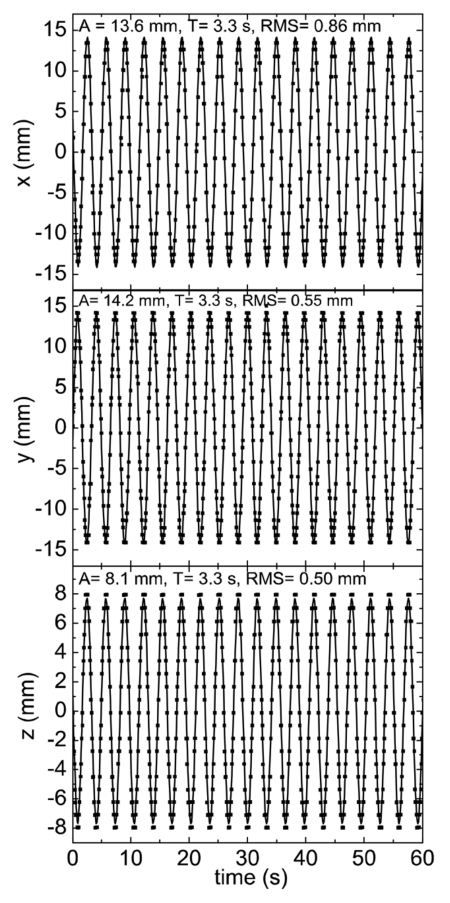
Using the system setup in Fig. 1, the pelvic phantom was oscillated at a fixed period of 3.4 s. The tracked fiducial motion from isocenter is plotted in Fig. 5 along all x, y, and z spatial components as a function of time. As can be seen, the tracked fiducial location undergoes sinusoidal motion with a fixed amplitude and period along the three coordinates. The tracked motion agrees well with the known movement of the fiducial embedded in the pelvic phantom. The measured amplitudes in the x- and y-axis directions are approximately 13.6 and 14.2 mm, respectively. These values are very close to 20∕√2 mm, as expected for a motion along 45°. As shown in Fig. 5, the theoretically sinusoidal function inputted in the motion platform (denoted by the solid curves) agrees well with the measured data points. Comparison of the expected and measured curves reveals RMS values of 0.86 and 0.55 mm for the x- and y-axis motion, respectively. The amplitude of fiducial movement along the z axis is measured to be 8.1 mm, which is also in close agreement with the actual 7.5 mm amplitude of the stage. Here the RMS is calculated to be 0.50 mm from the expected value. These measurements were done at a gantry angle of 180° and were repeated for different gantry angles of 90°, 135°, 270°, and 360°, in which similar results were obtained after applying Eq. 5.
Figure 5.
Plot of real-time fiducial motion along x, y, z obtained using simultaneous kV∕MV imaging. Motion is with respect to system isocenter. Solid curve is predicted motion. Deviation between predicted and experimental data points expressed as RMS.
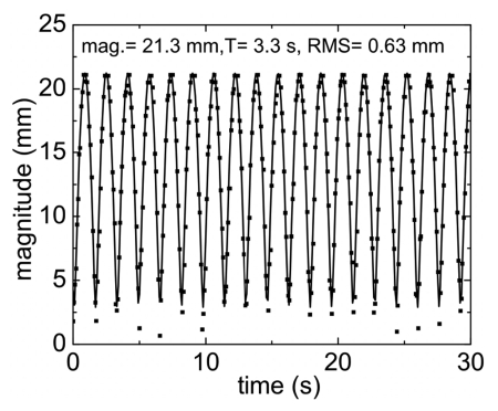
The net magnitude of the fiducial away from system isocenter is plotted in Fig. 6. From the figure it is seen that the amplitude of displacement of the fiducial from isocenter is ∼21.3 mm, which agrees well with the calculated ground truth value of 21.4 mm. The mean square deviation of the measured from the expected values is found to be 0.63 mm.
Figure 6.
Plot of magnitude of fiducial away from isocenter as a function of time. Solid curve is predicted motion with deviation between theoretical and experimental expressed as RMS.
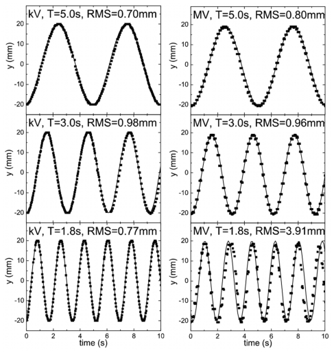
Investigation of system tracking speed response was accomplished by varying the platform period of oscillation from 5.0 s to the lowest settable value of 1.8 s. The measured y displacement for different frequencies were compared to each other and also to the known values shown in Fig. 7. This comparison is possible due to the geometric setup, where both kV and MV detectors are able to detect motion along the y axis (Fig. 1).
Figure 7.
Comparison of fiducial motion along the y axis at isocenter for the kV (left) and MV (right) detectors for different periods of oscillation. Solid curve is expected motion.
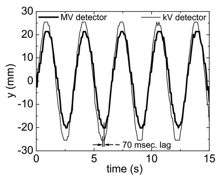
Figure 8 is a plot of the measured ykV and yMV as a function of time. The larger amplitude of the kV trace in comparison with the MV trace relates to the kV detector being further away from the system isocenter (dkV−d=80 cm) than the MV detector (dMV−d=50 cm), leading to increased magnification. As can be seen, it is found that the MV trace lags behind the kV trace by approximately ∼70 ms.
Figure 8.
Comparison of tracked real-time fiducial motion along the y axis as detected by the kV and MV detectors.
DISCUSSION
A critical step in dealing with intrafraction tumor motion is the real-time monitoring of the tumor position. Despite intense research effort in attempting to utilize the inherent image features to extract real-time information of tumor motion, at this point, implantation of metallic or electromagnetic field based fiducials remains the most reliable way to accomplish the stated goal. In this work we have described a combined kV∕MV fiducial tracking system using a commercially available Trilogy system. It allows us to monitor fiducial motion by use of the system’s pre-equipped onboard imager and EPID.
The program used for fiducial detection has the flexibility of allowing a large number of different types of image analysis techniques to be applied with minimal programming effort. Although, by no means a fully optimized and robust solution for the clinic, the fiducial detection algorithm, was found to be adequate in providing a proof-of-concept that kV∕MV tracking is indeed possible. The main weakness of the method used for fiducial segmentation and sequentially detection was it being intensity based in nature, and thus not robust against large intensity fluctuations. This may be problematic when the fiducial is moving in the vicinity of high density objects such as the bone that can have similar intensity values as the fiducial, resulting in loss of the tracking signal. Use of a ROI to remove any high contrast background objects from the analyzed area did correct this problem for the pelvic phantom used in this study, however, in actual patient situations, where fiducials can move below bony structure, loss of tracking signal may occur. In addition, an inherent problem with the use of EPID imaging is that the contrast between different material densities is significantly lower than with kV imaging. Even with the use of radio opaque markers as gold fiducials, the photon mass attenuation coefficient ratio (μ∕ρ)Au∕(μ∕ρ)H2O is near 1.0 at 1 MeV, compared to 30 at 100 keV. This poses a strong incentive in developing EPID image enhancement techniques targeted specifically to deal with poor material density distinction.
The 3.0 mm diameter stainless steel BB used in the study is larger than the gold fiducial markers used clinically (typically 1.2 mm in diameter and 3−5 mm in length). Due to the decrease in resolution as the frames are down converted from their native 1024×768 format to 640×480 for video based analysis, the subsequent worsening of image quality may make the use of the smaller clinical fiducials more problematic. For proof-of-concept demonstration that kV∕MV tracking is feasible, it was decided that a more easy to detect 3.0 mm BB should be employed. It is, however, envisioned that detection of smaller cylindrical gold fiducials is possible at a near real-time speed provided that one can access the native 1024×768 images directly captured by the kV and MV detectors. This would require cooperation with the equipment manufacturer and will be investigated in future work. In addition, a more advanced fiducial detection algorithm will most likely be necessary for the successful implementation of the kV∕MV tracking technique. Tang et al. have recently demonstrated tracking of multiple cylindrical fiducials through the use of pattern recognition and fiducial prediction.27 Additionally, their algorithm allowed tracking of fiducials near or under high density objects. Under current investigation is a prior knowledge based adaptive method capable of temporal and spatial marker prediction. The technique is particularly valuable in locating the fiducials that are partially or completely blocked by the MLC at certain segments during the IMRT delivery. It is anticipated that this type of fiducial detection algorithm will be useful for the kV∕MV tracking technique.
Currently, the ROI is manually defined by the operator through a process of visual inspection and identification of the fiducials in the kV and MV images. The ROI procedure is straightforward and can be done in less than a minute. This procedure can be further simplified by use of a pointer interface device, such as a computer mouse, to draw a ROI directly on the image as opposed to manual entry through the keyboard. A more automated approach is to use an algorithm to examine the prior planning CT image data to locate the fiducials and to evaluate their motion on the kV and MV imagers. A ROI, large enough to encompass the entire range of motion for the fiducial, can then be automatically defined around each fiducial.
To investigate velocity response of kV∕MV system, the 3 mm BB is oscillated at various sinusoidal frequencies as plotted in Fig. 7. As can be seen, for periods approximately T≥3 s, the detected pixel location of the fiducial corresponds well to the theoretically predicted position of a generated sinusoidal function with the corresponding amplitude and period set by the movable platform. For T<3 s, it is found that the kV detector is able to maintain a high fiducial tracking accuracy, whereas, the detected positions of the fiducial from the MV detector is found to deviate from the predicted ones. Visual observation of the kV and MV detector video streams reveals this as resulting from motion induced blurring. For all periods of oscillation produced by the motion stage it is seen that the kV detector accurately captures an image of the spherical BB without distortion. This is in contrast to the MV detector, where it is seen that for T=1.8 s, the spherical shape of the BB becomes elongated along the direction of motion. The image distortion is found to be most severe during mid, or the highest velocity, portion of the oscillation curve. In the T=1.8 s case, this corresponds to a BB velocity of ∼7 cm∕s at midoscillation. The elongated BB image resulted in a larger detected pixel group, leading to an erroneous center-of-mass pixel calculation. A motion restoration algorithm may be useful in this situation to deblur motion artifacts. However, in real patient scenarios, the maximum tumor velocity is generally observed to be less than 4 cm∕s. As shown by the T=3.0 s (maximum velocity ∼4.2 cm∕s) case, the response speed of the imagers should be adequate for most clinical situations.
As shown in Fig. 5, for a particular sinusoidal wave set by the moving stage, the kV∕MV tracking system measures a similar function that is found to differ no more than 1 mm RMS. Considering the 0.2 mm RMS error generated by the platform, it can be assumed that the kV∕MV system is measuring with an actual RMS under the reported values in Fig. 5. This is expected due to the detector pixel sizes being measured at ∼0.85 and ∼0.67 mm∕pixel at the surface of the detector, even with a down converted image frame (1024×768 to −640×480). With the amplification factor (∼1.5 in the kV∕MV system) the pixel size is further reduce to ∼0.57 and ∼0.44 mm∕pixel at the isoplane for the kV and MV imagers, respectively. These accuracy numbers are expected to further increase once full image frames at their native 1024×768 can be captured without down conversion.
As pointed out in a previous work,28 mechanical and electronic response times, that may be acceptable in 3D RT, can limit the precision of dose delivery in the 4D case. This is also seen in the presented kV∕MV tracking system, which, as detailed in Fig. 1, is comprised of two separate systems that each suffer from their own particular processing and electronic delay times. This manifests itself in the data of Fig. 8, where the phase of the MV signal lags behind the kV signal by approximately ∼70 ms. In calculating the fiducial coordinates using Eqs. 1, 2, 3, 4, this lag will lead to positional errors since the EPID position (xMV,yMV) is not in sync with the kV position (xkV,ykV) for a particular CPU clock cycle. In general, this systematic error can be corrected for by pairing the current MV imager (xMV,yMV) data with kV (xkV,ykV) data retrospectively delayed by 70 ms. Fortunately, in this study, the 70 ms processing delay resulted in a negligible positional error for all periods of oscillation investigated. Consultation with the manufacture revealed a ∼0.67 ms delay time for the kV imaging system. Combined with the 70 ms MV imager lag and associated video processing time a total delay time of ∼150−200 ms can be estimated. Since no prediction filters are used in the tracking system, the marker is measured with a ∼150−200 ms time lag. For short periods, or fast velocities, these electronic response times may hamper the geometric accuracy of fiducial tracking. Adaptive motion prediction filters29, 30, 31 may be useful in compensating for these electronic delay times. In general, response time is judged to be primarily a technological issue and will most likely be improved with the development of future fast response detector and image processing systems.
When using the pelvic phantom, it was found that scattered radiation from the treatment beam can blur the kV images. This is especially noticeable for isocenter-to-imager distances of dkV−d<70 cm. The scattered MV radiation superimposes over the kV imaging beam at the kV aSi detector, making fiducial detection difficult. Increasing dkV−d to 80 cm reduced the contribution of scattered MV photons, allowing detection of the fiducial using the aforementioned intensity based algorithm. Another potential solution for reducing the influence of the scattered MV radiation is the use of multiplexing through kV beam pulsation.32 This technique separates the kV source image from any MV scattered radiation, allowing dkV−d distances of less than 70 cm to be used. Another potential method would be through controlled kV∕MV beam switching (i.e., quick beam gating or pulsing), such that at a given instant of time, either the kV or MV source is on, but not both simultaneously. This would completely remove any MV radiation during the kV imaging process. It is also likely that the optimal kV∕MV switching rate will be disease site dependent. For certain sites, such as the prostate, it is expected that the kV beam is needed less frequently.
CONCLUSION
A real-time 3D fiducial tracking system using combined kV and MV imaging has been successfully demonstrated for the first time. This technique is especially suitable for RT systems already equipped with on board kV and EPID imaging devices. The geometric accuracy of the system is found to be on the order of 1 mm in all three spatial dimensions. Given its simplicity and achievable accuracy, the proposed approach, should find widespread clinical application in real-time monitoring of the tumor position and in providing a control signal to respiration-gated and even 4D radiation therapy.
ACKNOWLEDGMENTS
This work was supported in part by grants from the Komen Breast Cancer Foundation (BCTR0504071) and National Cancer Institute (1R01 CA98523 and CA104205).
U.S. Patent pending (Stanford Office of Technology Licensing, Disclosure #S07-268)
References
- Ezzell G. A. et al. , “Guidance document on delivery, treatment planning, and clinical implementation of IMRT: Report of the IMRT subcommittee of the AAPM radiation therapy committee,” Med. Phys. 10.1118/1.1591194 30, 2089–2115 (2003). [DOI] [PubMed] [Google Scholar]
- Xing L., Wu Q., Yong Y., and Boyer A. L., in Physics of IMRT and Inverse Treatment Planning in Intensity Modulated Radiation Therapy: A Clinical Perspective, edited by Mundt A. F. and Roeske J. C. (BC Decker, Inc., Hamilton, Canada, 2005), pp. 20–51. [Google Scholar]
- Shirato H. et al. , “Intrafractional tumor motion: Lung and liver,” Semin. Radiat. Oncol. 14, 10–18 (2004). [DOI] [PubMed] [Google Scholar]
- Xing L. et al. , “Overview of image-guided radiation therapy,” Med. Dosim. 31, 91–112 (2006). [DOI] [PubMed] [Google Scholar]
- van Herk M., “Errors and margins in radiotherapy,” Semin. Radiat. Oncol. 14, 52–64 (2004). [DOI] [PubMed] [Google Scholar]
- Hanley J. et al. , “Deep inspiration breath-hold technique for lung tumors: The potential value of target immobilization and reduced lung density in dose escalation,” Int. J. Radiat. Oncol., Biol., Phys. 10.1016/S0360-3016(99)00154-6 45, 603–611 (1999). [DOI] [PubMed] [Google Scholar]
- Kubo H. D. et al. , “Breathing-synchronized radiotherapy program at the University of California Davis Cancer Center,” Med. Phys. 10.1118/1.598837 27, 346 (2000). [DOI] [PubMed] [Google Scholar]
- Vedam S. S. et al. , “Determining parameters for respiration-gated radiotherapy,” Med. Phys. 10.1118/1.1406524 28, 2139–2146 (2001). [DOI] [PubMed] [Google Scholar]
- Li X. A., Stepaniak C., and Gore E., “Technical and dosimetric aspects of respiratory gating using a pressure-sensor motion monitoring system,” Med. Phys. 10.1118/1.2147743 33, 145–154 (2006). [DOI] [PubMed] [Google Scholar]
- Wink N. et al. , “Individualized gating windows based on four-dimensional CT information for respiration gated radiotherapy,” Med. Phys. 34, 2384 (2007). [DOI] [PubMed] [Google Scholar]
- Schweikard A. et al. , “Robotic motion compensation for respiratory movement during radiosurgery,” Comput. Aided Surg. 5, 263–277 (2000). [DOI] [PubMed] [Google Scholar]
- Keall P. J. et al. , “A four-dimensional controller for DMLC-based tumor tracking,” Int. J. Radiat. Oncol., Biol., Phys. 60, S338–S339 (2004). [Google Scholar]
- Ozhasoglu C., “Synchrony—Real-time respiratory compensation system for the CyberKnife,” Med. Phys. 33, 2245–2246 (2006). [Google Scholar]
- Keall P. J. et al. , “Motion adaptive x-ray therapy: A feasibility study,” Phys. Med. Biol. 10.1088/0031-9155/46/1/301 46, 1–10 (2001). [DOI] [PubMed] [Google Scholar]
- Neicu T. et al. , “Synchronized moving aperture radiation therapy (SMART): Average tumour trajectory for lung patients,” Phys. Med. Biol. 10.1088/0031-9155/48/5/303 48, 587–598 (2003). [DOI] [PubMed] [Google Scholar]
- Papiez L., “The leaf sweep algorithm for an immobile and moving target as an optimal control problem in radiotherapy delivery,” Math. Comput. Modell. 10.1016/S0895-7177(03)00081-5 37, 735–745 (2003). [DOI] [Google Scholar]
- Kubo H. D. and Hill B. C., “Respiration gated radiotherapy treatment: A technical study,” Phys. Med. Biol. 10.1088/0031-9155/41/1/007 41, 83–91 (1996). [DOI] [PubMed] [Google Scholar]
- Ozhasoglu C. and Murphy M. J., “Issues in respiratory motion compensation during external-beam radiotherapy,” Int. J. Radiat. Oncol., Biol., Phys. 10.1016/S0360-3016(01)02789-4 52, 1389–1399 (2002). [DOI] [PubMed] [Google Scholar]
- Simon L. et al. , “Lung volume assessment for a cross-comparison of two breathing-adapted techniques in radiotherapy,” Int. J. Radiat. Oncol., Biol., Phys. 10.1016/j.ijrobp.2005.05.020 63, 602–609 (2005). [DOI] [PubMed] [Google Scholar]
- Vedam S. S. et al. , “Quantifying the predictability of diaphragm motion during respiration with a noninvasive external marker,” Med. Phys. 10.1118/1.1558675 30, 505–513 (2003). [DOI] [PubMed] [Google Scholar]
- Hoisak J. D. P. et al. , “Correlation of lung tumor motion with external surrogate indicators of respiration,” Int. J. Radiat. Oncol., Biol., Phys. 10.1016/j.ijrobp.2004.07.681 60, 1298–1306 (2004). [DOI] [PubMed] [Google Scholar]
- Berbeco R. I. et al. , “Integrated radiotherapy imaging system (IRIS): Design considerations of tumour tracking with linac gantry-mounted diagnostic x-ray systems with flat-panel detectors,” Phys. Med. Biol. 10.1088/0031-9155/49/2/005 49, 243–255 (2004). [DOI] [PubMed] [Google Scholar]
- Shirato H. et al. , “Real-time tumour-tracking radiotherapy,” Lancet 10.1016/S0140-6736(99)00700-X 353, 1331–1332 (1999). [DOI] [PubMed] [Google Scholar]
- Kupelian P. et al. , “Multi-institutional clinical experience with the Calypso System in localization and continuous, real-time monitoring of the prostate gland during external radiotherapy,” Int. J. Radiat. Oncol., Biol., Phys. 67, 1088–1098 (2007). [DOI] [PubMed] [Google Scholar]
- Keall P. J. et al. , “On the use of EPID-based implanted marker tracking for 4D radiotherapy,” Med. Phys. 10.1118/1.1812608 31, 3492–3499 (2004). [DOI] [PubMed] [Google Scholar]
- Roborealm, http://roborealm.com/.
- Tang X. L., Sharp G. C., and Jiang S. B., “Fluoroscopic tracking of multiple implanted fiducial markers using multiple object tracking,” Phys. Med. Biol. 52, 4081–4098 (2007). [DOI] [PubMed] [Google Scholar]
- Wiersma R. D. and Xing L., “Examination of geometric and dosimetric accuracies of gated step-and-shoot intensity modulated radiation therapy,” Med. Phys. 34, 3962–3970. [DOI] [PubMed] [Google Scholar]
- Sharp G. C. et al. , “Prediction of respiratory tumour motion for real-time image-guided radiotherapy,” Phys. Med. Biol. 10.1088/0031-9155/49/3/006 49, 425–440 (2004). [DOI] [PubMed] [Google Scholar]
- Vedam S. S. et al. , “Predicting respiratory motion for four-dimensional radiotherapy,” Med. Phys. 10.1118/1.1771931 31, 2274–2283 (2004). [DOI] [PubMed] [Google Scholar]
- Murphy M. J., “Tracking moving organs in real time,” Semin. Radiat. Oncol. 14, 91–100 (2004). [DOI] [PubMed] [Google Scholar]
- Zhang J. et al. , “Multiplexing radiography for ultra-fast computed tomography: A feasibility study,” Med. Phys. 34, 2527 (2007). [Google Scholar]


