Abstract
Vascular cross-clamping is applied in many cardiovascular surgeries such as coronary bypass, aorta repair, and valve procedures. Experimental studies have found that clamping of various degrees caused damage to arteries. This study examines the effects of popular clamps on vessel wall. Models of the aorta and clamp were created in Computer Assisted Design and Finite Element Analysis packages. The vessel wall was considered as a non-linear anisotropic material while the fluid was simulated as Newtonian with pulsatile flow. The clamp was applied through displacement time function. Fully coupled two-way solid-fluid interaction models were developed. It was found that the clamp design significantly affected the stresses in vessel wall. The clamp with a protrusion feature increased the overall Von Mises stress by about 60% and the compressive stress by more than 200%. Interestingly, when the protrusion clamp was applied, the Von Mises stress at the lumen (endothelium) side of artery wall was about twice that of the outer wall. This ratio was much higher than that of the plate-like clamp which was about 1.3. The flow reversal process was demonstrated during clamping. Vibrations, flow and wall shear stress oscillations were detected immediately before total vessel occlusion. The commonly used protrusion clamp increased stresses in vessel wall, especially the compressive stress. This design also significantly increased the stresses on endothelium, detrimental to vessel health. The present findings are relevant to surgical clamp design as well as the transient mechanical loading on the endothelium and potential injury. The deformation and stress analysis may provide valuable insights into the mode of tissue injury during cross-clamping.
Keywords: Fluid-structure Interaction, Surgical clamp designs, Intramural wall stress, Wall Shear Stress, Endothelium
INTRODUCTION
Vascular cross-clamping is applied in many cardiovascular surgeries such as coronary bypass, aorta repair, and valve procedures. Although some clamps are marketed as so called “atraumatic”, evidence suggests otherwise. Experimental studies have found that clamping of various degrees causes various degrees of damage to the artery, from endothelium denudation to severe intima injury as observed with histology and Scanning Electron Microscope. (3, 7–8, 20–21, 30)
Endothelial damage increases platelet uptake and may lead to accumulation of thrombus with the risk of vessel occlusion. (20–21) Studies by Margovsky, et al found that deposition of platelets was proportional to endothelial damage. Functional studies on vessel dilation or constriction also revealed long term effects of clamping on vessel functions. Intramural stress concentrations in the vessel wall and related injuries have been linked to disease processes such as lipid invasion and calcification. (16, 23) Aortic cross-clamping has been considered risky and a culprit in adverse outcomes, such as strokes following coronary bypass surgery. (9) The reason stems from the unpredictable atheroma in the aorta that could be released during cross-clamping.
Since aortic clamping alone is performed in about half million patients per year worldwide (25), a safer clamp would benefit many patients. The aim of this study is to provide insights and guidance for clamp design. A common design feature of popular atraumatic clamps involves a protruded clamp area for better gripping to prevent tissue slippage. The hypothesis of this study is that such a design feature may induce stress concentrations and is thus more prone to causing tissue injury. The vessel deformation and stress analysis can provide valuable insights into the mode of injury (7, 12, 20–21).
Despite the apparent clinical significance, however, there have been few computational studies of clamping. To our knowledge, the only clamp simulations have been provided by Gasser, et al, 2002 and Calvo, et al, 2007, both of which did not consider fluid or Fluid-solid Interaction (FSI). Furthermore, the models were not able to occlude completely (90% in Gasser, et al and 60% in Calvo, et al) and difficulties in achieving convergence when the vessel was highly deformed were cited. The objective of the present study was to develop a computational clamp model capable of full closure, incorporates FSI and is based on anisotropy of the vessel wall.
METHODS
The computational models were created in a Computer Assisted Design package –Pro/Engineer and solved in a well validated Finite Element Analysis package -ADINA. For the present application, the aorta was modeled as soft, non-linear material and the clamp was modeled as rigid. Anisotropic material properties were considered. The detailed formulations are outlined in the Appendix. Two kinds of clamps were modeled: a rectangular plate shaped clamp representative of the Satinsky clamp and a clamp with a protrusion feature designed for the purpose of more tissue gripping, representative of clamps similar to the Cooley clamp. The stresses in the vessel wall as well as the fluid wall shear stresses imposed by the two clamps were compared. The clamp was applied through a linear displacement time function to produce total occlusion in about 1 second.
Geometry and Mesh
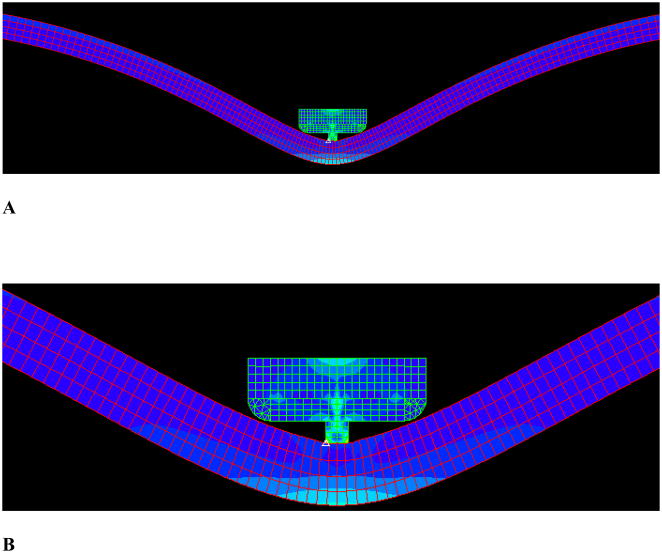
The vessel segment was 80 mm long and 16.5 mm in diameter, representative of a typical ascending aorta. (Fig. 1) The length was chosen to facilitate computation and to allow recirculations to develop. The clamp edges were designed with rounded edges to avoid stress concentrations caused by sharp corners. The vessel wall and fluid meshes were structured and refined toward the clamped region with a ratio of 4:1 or four times denser. Mesh for the clamp was also carefully structured and refined. A mesh convergence test showed that doubling the number of elements only resulted in less than 3% difference in wall shear stress and peak von Mises stresses. The stress distributions also did not change appreciably. Hence, the mesh density was sufficient for the proposed simulations.
Figure 1.
The geometry and mesh of the clamp with protrusion. A) Overall view; B) Zoom-in view.
Fluid-structure Interaction
Fluid-structure interfaces were defined at the lumen surfaces of the vessel, and the wall boundaries of the fluid. The ALE (Arbitary Lagrange-Eulerian) method was used. This method allows the fluid mesh to deform around the moving vessel, which is necessary for this application with the large deformation. Instead of using either a single Lagrangian approach or a single Eulerian approach, the ALE describes the motion of fluid in a moving reference frame. The detailed descriptions of FSI can be found in the Appendix.
RESULTS
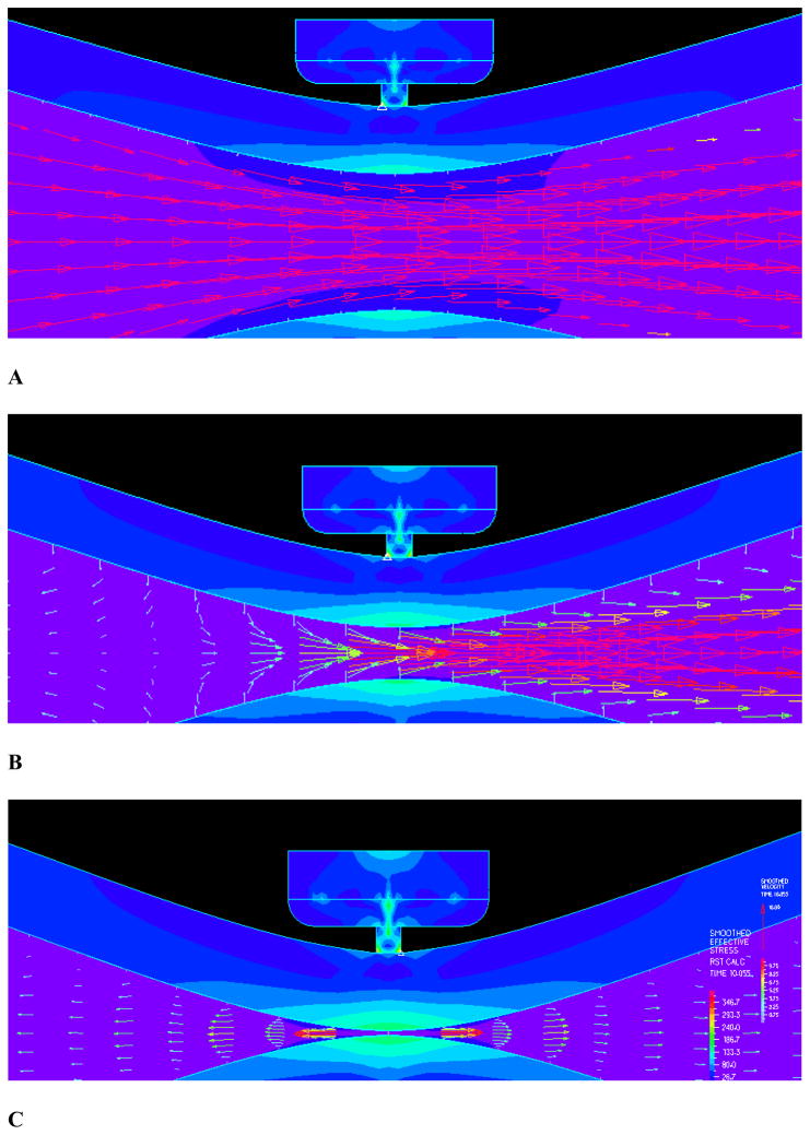
The simulation results were independent of the time steps, as various time steps were attempted and the resulting stress and wall shear stress patterns and magnitudes were very similar. A total of six hundred time steps were used in the current simulations. The flow field near closure is shown in Figure 3 where strong FSI is observed. A dramatic reduction of flow velocity near closure is observed. Figure 3A shows the flow field with mostly forward flow while Fig. 3B shows flow field during the transition to reversal. In the final stage of clamping, the flow clearly reversed upstream as shown in 3C. As can be seen from panel 3B, the flow upstream were reduced to almost zero where the flow vectors near the boundary were already negative while the center flow was still forward. This is the transition point when the flow starts to reverse. Panel C shows the flow field after the reversal with well defined negative flow with parabolic profile.
Figure 3.
The flow field and detailed flow features: A) The flow field with mostly forward flow; B) Flow field during the transition to reversal; C) Final stage of clamping with the flow clearly reversed upstream.
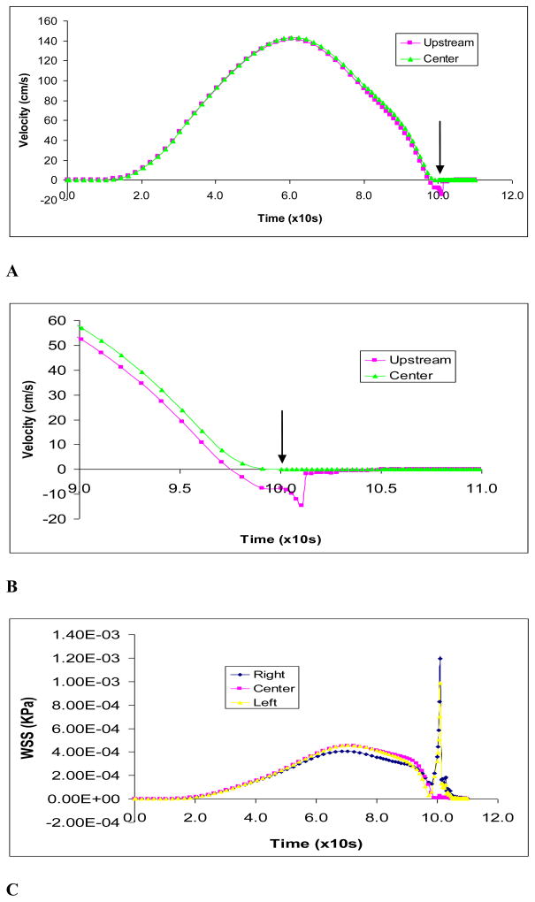
The maximum flow velocity during clamping is shown in Fig. 4A. The predicted maximum flow velocity of 1.35 m/s is consistent with the aortic flow experimental data [27]. Figure 4B shows the flow velocity upstream of the clamp. The velocities immediately upstream (3 mm from occlusion) was plotted. During the final stage of clamping (at about 90% occlusion), flow reversal in the upstream section was observed as indicated by the negative flow. The wall shear stress on vessel wall is shown in Fig. 4C. The wall shear stress spiked before closing and a high shear in the occlusion region is observed as expected. The shear stress at the endothelium had large peaks immediately (3 mm) upstream and downstream of occlusion at clamp center in the vessel. Oscillations were also indicated during closure which caused significant oscillatory shear stress.
Figure 4.
Figure 4A): The maximum fluid flow velocity during clamping by protrusion clamp at occlusion area; B) The maximum fluid flow velocity during final stage of clamping at near occlusion (3 mm away) and occlusion areas; C) Wall shear stresses on vessel endothelium by protrusion clamp at center of clamped area and immediately (3 mm) upstream and downstream.
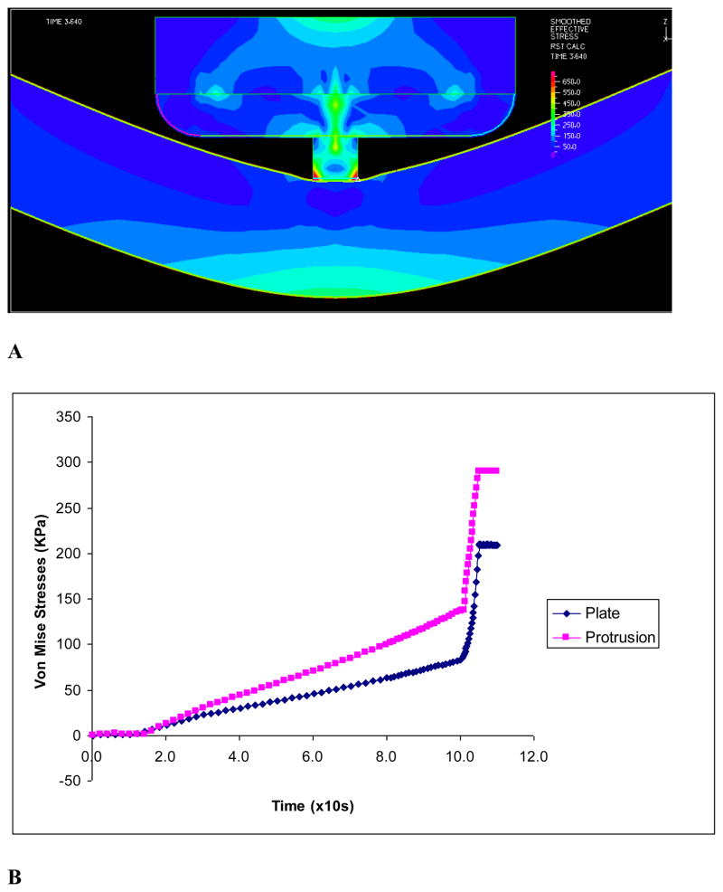
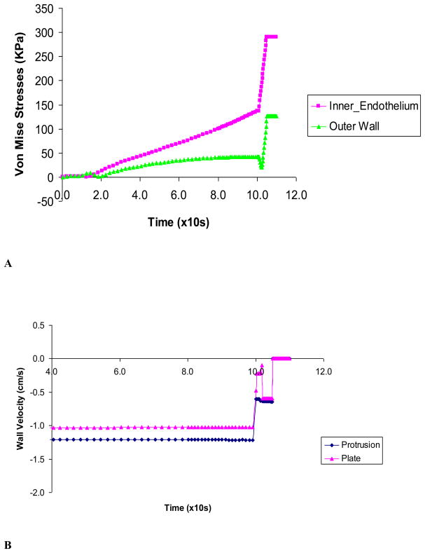
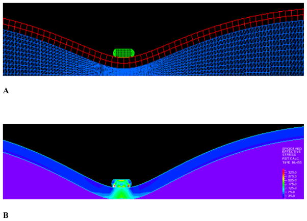
The solid stresses in the vessel wall induced by the two types of clamps were compared. The maximum Von Mises stresses with displacement driven clamp is plotted in Fig. 5. It is shown that the maximum Von Mises stresses in the vessel wall (lumen side of clamped area) are much higher with the clamp with protrusion. The stresses spiked as the tissue was being compressed near closure (Figs. 5 & 6).
Figure 5.
The vessel wall stresses induced by the protrusion clamp: A) Stress profile in vessel wall and clamp before closure; B) The maximum Von Mises stresses in vessel wall induced during clamping
Figure 6.
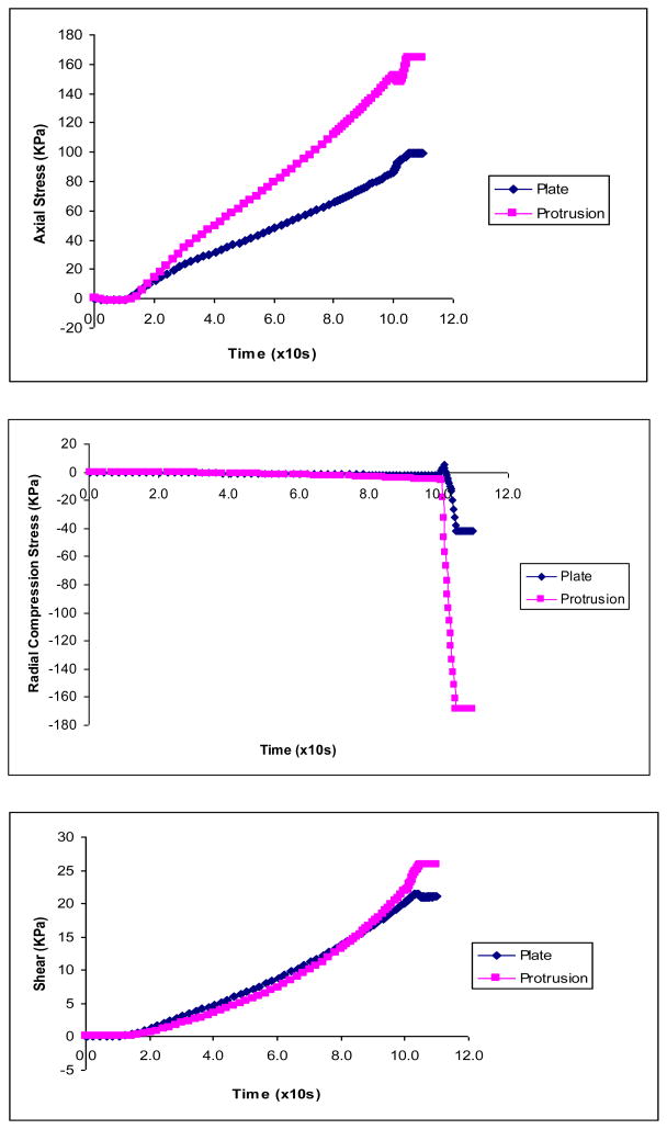
The axial, radial and shear stress components caused by the plate and protrusion clamps.
The protrusion clamp caused much larger stresses than the plate clamp in each of the stress components, e.g., radial compression of −170 vs −45 KPa (Fig. 6A& B). For the protrusion clamp, the simulation shows that the radial compression and axial stresses were large at closure: −170 KPa and 160 KPa, respectively. In comparison, shear was modest at about 25 KPa. For the plate like clamp, the simulation revealed that axial stresses (90 KPa) were larger than compressive (−45 KPa) and shear stresses (20 KPa). Figure 6C shows the shear stress caused by the plate and protrusion clamps.
Figure 7A shows the maximum stresses at the inner and outer vessel wall caused by protrusion clamp. It is seen that the maximum stresses in the vessel wall (lumen side of clamped area) are much higher with the protrusion clamp. The maximum Von Mises stress spiked as the tissue was being compressed near closure. Figure 7B shows the vessel wall velocity during clamping by the two kinds of clamps. The wall velocity changed rapidly towards closure, just before the wall motion ceased. The vessel wall under the plate clamp had higher rate of change of wall velocity or acceleration. This large fluctuation of velocity indicates vibration of the vessel wall.
Figure 7.
Figure 7A) The Von Mises stresses caused by the protrusion clamp at the inner and outer vessel wall; B) Vessel wall velocity during clamping by plate and protrusion clamps. Rapid changes of wall velocity indicate vibration just before closure.
DISCUSSION
This paper explores the effects of clamp design for two popular vessel clamps. The simulations show that the clamp design significantly alters the stresses in vessel wall. Vibrations were detected immediately before total vessel closure. The so called “atraumatic” clamps exert significant stress on the vessel wall and particularly in the intima during total occlusion. The limitations and implications of the model are enumerated.
Solid Mechanics
The sharp edges of the protrusion caused difficulties in achieving convergence during contact with vessel wall; as the result, the time steps were very small and numerous, totaling 600 steps. The maximum stresses in the arterial wall were higher on the inner than the outer surface at full occlusion (Figs. 7A). This is important as the endothelium resides on the lumen side of the artery. Furthermore, as the media and intima are less capable of carrying axial and compressive loads than the outer advantitia, these higher stresses may damage the more vulnerable intima and media. (14, 26)
It was found that the protrusion clamp caused much larger stresses than the plate clamp in each of the stress components: e.g. radial compression of −175 vs −40 KPa, axial stresses, 170 vs 100 KPa and shear stresses, 25 vs 20 KPa (Figs 5 & 6). In the case of the protrusion clamp, the simulations show that the radial compression and axial stresses had the largest magnitudes (−175 KPa and 170 KPa, respectively). Therefore, the injury mechanism is likely to stem from compression and axial stresses caused by the clamps (Fig. 6). The vessel may be more prone to injury by the large compressive stress during closure since the aorta normally does not experience significant compression. The high compressive stresses predicted by the model are consistent with vessel clamp injuries as revealed by histological studies (20–21).
In the case of the plate like clamp, the simulations show that axial stresses were larger than compression and shear stresses (90 KPa vs −50 KPa & 20 KPa, respectively). (Fig. 6) It should be pointed out that even stress magnitudes that are considered non-destructive could have long term effects as revealed by experimental studies on vessel functionality such as the ability to relax or constrict (1). Intramural stress concentrations in the vessel wall and related injuries have also been linked to disease processes such as lipid invasion and calcification. Stress induced injuries would initiate the inflammatory response.
Fluid Dynamics
Figures 3 & 4 illustrate the dynamic and highly transient nature of the fluid during the closure process and support the importance of implementing the FSI model. Fluid shear stresses became higher towards vessel wall where endothelium resides. It is well known that abnormally low or high wall shear stress have effects on endothelial biology (17–19). It can be seen from Fig. 5 that the wall shear stress spiked during closure indicating high rate of change of wall shear stress which may activate platelets leading to micro emboli formation.(29) Although these effects are transient and hence acute, they may cause early thrombosis. (Figs. 3 & 4) Indeed, experimental studies by Margovsky, et al, (20–21) found that endothelial damage from “atraumatic” clamps increased platelet uptake and may lead to accumulation of thrombus with the risk of thrombosis or vessel occlusion. They further found that deposition of platelets on the clamped surface was proportional to the extent of endothelial lesions.
The predicted maximum flow velocity of 1.35 m/s (Fig. 4A) is consistent with the aortic flow experimental data [27]. Although this model was used to study the cross-clamping process, the FSI model can also simulate various stages of stenosis, 80%, 90%, 95%, etc. (Fig. 3). Fig 3b demonstrates that at about 80% occlusion, flow reversal in the upstream section was observed as indicated by the negative flow. This has important implications as reverse flow can cause endothelium to produce more superoxides which can scavenge nitric oxide. (15, 17)
For the purpose of reducing the wall stresses (Figs. 5 & 6), the plate clamp design was superior. The likely reason is that under the rectangular clamp, there is an elongated contact area which reduces and smoothes the stress.
Comparisons with Previous Studies
In a clamping study by Gasser, et al (2002), the model did not have fluid or FSI and did not attain total occlusion. In a recent clamping study by Calvo, et al (2007), the model also was not coupled with fluid and achieved occlusion level of 60%. The authors reported that axial stresses at the inner wall were significantly increased and were cited as the potential culprit for vessel injury. Here we show that the radial compression can be very significant as the vessel is occluded. During the closure process, Fig. 5 shows that the overall effective stresses rose to about twice as high as the magnitude before closure. Importantly, Gasser et al and Calvo et al studies did not identify the high compressive stress as their models did not reach closure during which the compressive stress spikes. As shown in Fig. 6B, the compressive stress was nearly negligible until closure was reached. It was only during the closure that the compressive stress rose dramatically. This is an important finding as it reveals a potentially important mechanism of tissue injury. This prediction by the FSI model is consistent with histological observations of clamp injuries in the experimental studies by Margovsky et al. which clearly showed compressive injuries (20, 21).
Limitations of Model
The plate-like clamp in the current model has a smooth contact surface. Some surgical clamps have tiny teeth like surfaces. A model incorporating this feature is under development. Future models will also include contact with friction.
This is a model of normal aorta where a disease state such as hypertension with thicker and stiffer vessel wall, was not considered. In future models, the dimensions and material properties for the vessel model can be adjusted accordingly. A stiffer aorta will have higher wall stresses at a given deformation. The relative trend, however, is likely to be similar when comparing the different clamp designs. Furthermore, various hemodynamics (pressure, heart rate, flow, etc.) can be inputted into the model. Ideally measurements can be made from the patient to allow a patient specific analysis.
The current model did not incorporate plaque structures in the vessel wall which is relatively common in patients requiring cross-clamping. (8, 22) Future models should include the non-homogenous structure of the vessel wall, i.e., calcification and lipid pool. These plaque structures may create local stress concentrations. It should be noted that FSI simulations are 10–20 times more computationally demanding than CFD or fluid only simulations. Given the complexity of FSI models, it is necessary to take a step by step approach.
Significance of Study
The present model simulates the aortic cross-clamping process with emphasis on the effects of clamp geometry on the closure dynamics of solid and fluid. Both the fluid and solid mechanics during the closure process are found to be highly transient and dynamic. The utility of the model is to enable optimization of the design of clamps that may cause less trauma to arteries. Clearly, the protrusion design feature is traumatic to the arterial wall and better designs are warranted. The vibrations during the closure process may be used for development of a clamp with a sensor that can detect such vibrations.
Future Studies
This model may serve as a guide for in silico design of clamps. A number of notable observations were made here that can impact design of better clamps. For example, a flat plate type of design is less traumatic than the present so called “atraumatic” design. The flat plate design reduces the wall stress, and also results in larger vibration signal. The vibration signal predicted by the simulations could be used for a “smart” clamp that avoids wall damage by stopping as soon as near total occlusion is achieved.
Future models could be developed as optimization tools. The detailed stress and flow analysis cannot be easily done through experimental means. The models could be used for design optimization, i.e., to obtain the optimal width of the clamp, etc. For the case of protrusion clamp, the effects of length and width of the protrusion feature; the effects of the clamp material, e.g., with rubber coating, resin stem, metal stem, etc. These simulations may save both time and cost of building and testing various prototypes.
Supplementary Material
Figure 2.
Figure 2A):The geometry and mesh of the plate-like clamp; B) Stress distribution.
Acknowledgments
The first author appreciates the helpful discussions with Drs. Wei Zhang and Yi Liu. He is also grateful for Dr. Daniel Einstein’s assistance and guidance when they were with the Univ. of Southern California. The critical review of manuscript by Prof. Luoding Zhu is also greatly appreciated. This research was supported in part by the National Institute of Health-National Heart, Lung, and Blood Institute Grant HL087235 and HL086400.
Footnotes
Publisher's Disclaimer: This is a PDF file of an unedited manuscript that has been accepted for publication. As a service to our customers we are providing this early version of the manuscript. The manuscript will undergo copyediting, typesetting, and review of the resulting proof before it is published in its final citable form. Please note that during the production process errors may be discovered which could affect the content, and all legal disclaimers that apply to the journal pertain.
References
- 1.Barone GW, Conerly JM, Farley PC, Flanagan TL, Kron IL. Assessing clamp-related vascular injuries by measurement of associated vascular dysfunction. Surgery. 1989 Apr;105(4):465–71. [PubMed] [Google Scholar]
- 2.Bittner HB, Savitt MA. Management of porcelain aorta and calcified great vessels in coronary artery bypass grafting with off-pump and no-touch technology. Ann Thorac Surg. 72(4):1378–1380. doi: 10.1016/s0003-4975(01)02568-1. [DOI] [PubMed] [Google Scholar]
- 3.Bathe KJ. Finite Element Procedures. Prentice-Hall: Englewood Cliffs; 1995. p. 1037. [Google Scholar]
- 4.Butcher JT, Nerem RM. Valvular endothelial cells regulate the phenotype of interstitial cells in co-culture: effects of steady shear stress. Tissue Eng. 2006 Apr;12(4):905–15. doi: 10.1089/ten.2006.12.905. [DOI] [PubMed] [Google Scholar]
- 5.Calvo B, Martínez MA, Peña E, Doblaré M. A Directional Damage Model For Fibred Biological Soft Tissues. Int J Numer Meth Engng. 2007;69:2036–2057. [Google Scholar]
- 6.Charles L. Fefferman, Existence & Smoothness of the Navier–stokes equation. Princeton University, Department of Mathematics; Princeton, NJ: May 1, 2000. [Google Scholar]
- 7.Coelho JC, Sigel B, Flanigan DP, Schuler JJ, Justin J, Machi J. Arteriographic and ultrasonic evaluation of vascular clamp injuries using an in vitro human experimental model. Surg Gynecol Obstet. 1982;155(4):506–12. [PubMed] [Google Scholar]
- 8.Demirsoy E, Unal M, Arbatli H, Yagan N, Tukenmez F, Sonmez B. Extra-anatomic coronary artery bypass graftings in patients with porcelain aorta. J Cardiovasc Surg. 2004;45(2):111–5. [PubMed] [Google Scholar]
- 9.Ross Donald E. Chasing the Wrong Villain. 2006 May 22; http://www.ctsnet.org/sections/newsandviews/inmyopinion/articles/article-58.html.
- 10.Fung YC. Biomechanics: Circulation. Springer-Verlag; New York: 1996. [Google Scholar]
- 11.Fung YC. Biomechanics: Motion, Flow, Stress, and Growth. Springer-Verlag; New York: 1998. [Google Scholar]
- 12.Gasser TC, Schulze-Bauer CA, Holzapfel GA. A three-dimensional finite element model for arterial clamping. J Biomech Eng. 2002 Aug;124(4):355–63. doi: 10.1115/1.1485284. [DOI] [PubMed] [Google Scholar]
- 13.Holzapfel GA, Gasser TC, Ogden RW. A new constitutive framework for arterial wall mechanics and a comparative study of material models. Journal of Elasticity. 2000;61 (1–3):1–48. [Google Scholar]
- 14.Jackiewicz TA, McGeachie JK, Tennant M. Structural recovery of small arteries following clamp injury: a light and electron microscopic investigation in the rat. Microsurgery. 1996;17(12):674–80. doi: 10.1002/(SICI)1098-2752(1996)17:12<674::AID-MICR4>3.0.CO;2-N. [DOI] [PubMed] [Google Scholar]
- 15.Kassab GS, Navia JA, Lu X. Proper Orientation of the Graft Artery Is Important to Ensure Physiological Flow Direction. Ann Biomed Eng. 2006 May 24; doi: 10.1007/s10439-006-9104-x. [DOI] [PubMed] [Google Scholar]
- 16.Li QY, Jones PL, Lafferty RP, Safer D, Levy RJ. Thymosin beta4 regulation, expression and function in aortic valve interstitial cells. J Heart Valve Dis. 2002 Sep;11(5):726–35. ts, (2003) 14, 11–17. [PubMed] [Google Scholar]
- 17.Lu X, Kassab GS. Nitric oxide is significantly reduced in ex vivo porcine arteries during reverse flow because of increased superoxide production. J Physiol. 2004;561:575–82. doi: 10.1113/jphysiol.2004.075218. [DOI] [PMC free article] [PubMed] [Google Scholar]
- 18.Malaviya P, Nerem RM. Fluid-induced shear stress stimulates chondrocyte proliferation partially mediated via TGF-beta1. Tissue Eng. 2002;8(4):581–90. doi: 10.1089/107632702760240508. [DOI] [PubMed] [Google Scholar]
- 19.Malek AM, Alper SL, Izumo S. Hemodynamic shear stress and its role in atherosclerosis. JAMA. 1999;282(21):2035–42. doi: 10.1001/jama.282.21.2035. [DOI] [PubMed] [Google Scholar]
- 20.Margovsky AI, Chambers AJ, Lord RS. The effect of increasing clamping forces on endothelial and arterial wall damage: an experimental study in the sheep. Cardiovasc Surg. 1999 Jun;7(4):457–63. doi: 10.1016/s0967-2109(98)00154-9. [DOI] [PubMed] [Google Scholar]
- 21.Margovsky AT, Lord RSA, Meek AC, Bobryshev YV. Artery wall damage and platelet uptake from so-called atraumatic arterial clamps: an experimental study. Cardiovascular Surgery. 1997;5:42–47. doi: 10.1016/s0967-2109(96)00064-6. [DOI] [PubMed] [Google Scholar]
- 22.Mehrabi MR, Sinzinger H, Ekmekcioglu C, Tamaddon F, Plesch K, Glogar HD, Maurer G, Stefenelli T, Lang IM. Accumulation of oxidized LDL in human semilunar valves correlates with coronary atherosclerosis. Cardiovasc Res. 2000 Mar;45(4):874–82. doi: 10.1016/s0008-6363(99)00389-2. [DOI] [PubMed] [Google Scholar]
- 23.Deiwick Michael, Glasmacher Birgit, Baba Hideo A, Roeder Norbert, Reul Helmut, von Bally Gert, Scheld Hans H. In vitro testing of bioprostheses: influence of mechanical stresses and lipids on calcification. Ann Thorac Surg. 1998 Dec;66(6 Suppl):S206–11. doi: 10.1016/s0003-4975(98)01125-4. [DOI] [PubMed] [Google Scholar]
- 24.Seo T, Schachter LG, Barakat AI. Computational study of fluid mechanical disturbance induced by endovascular stents. Ann Biomed Eng. 2005 Apr;33(4):444–56. doi: 10.1007/s10439-005-2499-y. [DOI] [PubMed] [Google Scholar]
- 25.STS Adult CV Surgery National Database, Spring 2007 Executive Summary, Duke University Medical Center.
- 26.Slayback JB, Bowen WW, Hinshaw DB. Intimal injury from arterial clamps. Am J Surg. 1976 Aug;132(2):183–8. doi: 10.1016/0002-9610(76)90045-3. [DOI] [PubMed] [Google Scholar]
- 27.Seifert BL, DesRochers K, Ta M, Giraud G, Zarandi M, Gharib M, Sahn DJ. Accuracy of Doppler methods for estimating peak-to-peak and peak instantaneous gradients across coarctation of the aorta: An In vitro study. J Am Soc Echocardgr. 1999 Sep;12(9):744–53. doi: 10.1016/s0894-7317(99)70025-8. [DOI] [PubMed] [Google Scholar]
- 28.Tanyana A, Jackiewicz JKM, Tennant Marc. Structural recovery of small arteries following clamp injury: A light and electron microscopic investigation in the rat. Microsurgery. 17(12):674–680. doi: 10.1002/(SICI)1098-2752(1996)17:12<674::AID-MICR4>3.0.CO;2-N. [DOI] [PubMed] [Google Scholar]
- 29.Wolf LG, Abu-Omar Y, Choudhary BP, Pigott D, Taggart DP. Gaseous and solid cerebral microembolization during proximal aortic anastomoses in off-pump coronary surgery: the effect of an aortic side-biting clamp and two clampless devices. J Thorac Cardiovasc Surg. 133(2):485–93. doi: 10.1016/j.jtcvs.2006.10.002. [DOI] [PubMed] [Google Scholar]
Associated Data
This section collects any data citations, data availability statements, or supplementary materials included in this article.


