Abstract
X-ray scattering features induced by aggregates of alamethicin (Alm) were obtained in oriented stacks of model membranes of DOPC(diC18:1PC) and diC22:1PC. The first feature obtained near full hydration was Bragg rod in-plane scattering near 0.11 Å-1 in DOPC and near 0.08 Å-1 in diC22:1PC at 1:10 Alm:lipid ratio. This feature is interpreted as bundles consisting of N Alm monomers in a barrel-stave configuration surrounding a water pore. Fitting the scattering data to previously published MD simulations indicates that the number N of peptides per bundle is N=6 in DOPC and N≥9 in diC22:1PC. The larger bundle size in diC22:1PC is explained by hydrophobic mismatch of Alm with the thicker bilayer. A second diffuse scattering peak located at qr≈0.7 Å-1 is obtained for both DOPC and diC22:1PC at several peptide concentrations. Theoretical calculations indicate that this peak can not be caused by the Alm bundle structure. Instead, we interpret it as due to two-dimensional hexagonally packed clusters in equilibrium with Alm bundles. As the relative humidity was reduced, interactions between Alm in neighboring bilayers produced more peaks with three dimensional crystallographic character that do not index with the conventional hexagonal space groups.
Keywords: alamethicin, aggregation, hydrophobic mismatch, water pore, helix bundle, ion channel
Introduction
It is becoming increasingly appreciated that the lipids play an important role in membrane biochemistry (Phillips et al. 2009) by modulating protein function (Brown 1994) and lateral organization (Baumgart et al. 2003). Differences in the curvature stress (Gruner and Shyamsunder 1991) or the lateral pressure profile (Cantor 1997) in bilayers of different lipids likely alter the energy of the transition state and the kinetics of protein conformation changes. The energy cost of membrane deformation caused by hydrophobic mismatch between the hydrophobic core of the lipid membrane and the protein’s hydrophobic domain depends on membrane thickness, bending elasticity, area stretch modulus, and intrinsic curvature (Huang 1986; Andersen and Koeppe 2007). Therefore, membrane protein structure and function can be modulated by varying the mechanical and structural properties of lipid bilayers (McIntosh and Simon 2006).
One particular interest in this paper is to investigate how the size of the ion channels (bundles) formed by the antimicrobial peptide alamethicin (Alm) changes as a function of lipid properties. Macroscopic and single channel (Hall et al. 1984; Sansom 1991; Woolley and Wallace 1992; Cafiso 1994) conductance measurements have indicated that the conductance behavior of the Alm channel depends on lipid properties. A larger probability for higher conductance states (larger N) has been observed when Alm inserts into PE lipids which have a smaller headgroup than the typical bilayer forming PC lipids (Keller et al. 1993).
Stable barrel-stave (Baumann and Mueller 1974) Alm bundles have been observed by applying neutron (He et al. 1995; He et al. 1996) and x-ray (Constantin et al. 2007; Qian et al. 2008) scattering techniques where no external voltage was present. The neutron studies showed that the bundles encompassed a water pore. These stable bundles may be different from the dynamic single channels in conductance measurements (Qian et al. 2008). The average number of Alm monomers N per bundle has been estimated by model fitting to x-ray scattering (Constantin et al. 2007) or to neutron scattering (He et al. 1995; He et al. 1996). In part I of our Results and Discussion section, we use similar model fitting procedures to our x-ray scattering data to investigate the Alm bundle size in two lipid model membranes, DOPC and diC22:1PC. These bilayers have similar properties except that diC22:1PC is about 7 Å thicker than DOPC (Kučerka et al. 2005b).
We observe a second peak that has also been previously observed and interpreted as due to barrel-stave bundles (He et al. 1996), but our analysis does not allow us to agree with this assignment and we have been forced to consider an alternative, coexisting structure in part II of Results and Discussion. Finally, in part III, we present data on partially dehydrated samples, in which the interactions between neighboring bilayers in our stacked samples become strong. A confusing variety of crystallographic packing patterns appears as one proceeds away from the fully hydrated biological condition and, while interesting solid state physics and crystallographic problems can be addressed, we conclude that such samples should not be preferred for determination of Alm bundle structure.
Materials and Methods
Sample preparation
1,2-dioleoyl-sn-glycero-phosphatidylcholine (DOPC) and 1,2-dierucoyl-sn-glycero-phosphatidylcholine (di22:1PC) were purchased from Avanti Polar Lipids (Alabaster, AL). Alm was purchased from Sigma-Aldrich (Milwaukee, WI). This is a natural, purified 20 amino-acid peptide from Trichoderma viride consisting of 85% Alm I and 15% Alm II. The primary structure of Alm I is acetyl-Aib-Pro-Aib-Ala-Aib-Ala-Gln-Aib-Val-Aib-Gly-Leu-Aib-Pro-Val-Aib-Aib-Glu-Gln-Phol. Alm II differs from Alm I in the amino acid at the 6th position: Aib in Alm II instead of Ala in Alm I.
4 mg of pure lipid was added to a chloroform:trifluoroethanol (TFE) solvent mixture (v:v 2:1 or 1:1) and to this was added the appropriate amount of Alm from a chloroform stock solution (1 mg/ml). Peptide to lipid mole ratios between 1:75 and 1:10 were studied. The mixture was plated onto the 1.5cm×3cm surface of a polished silicon wafer using the rock and roll procedure (Tristram-Nagle et al. 1993; Tristram-Nagle 2007). The samples were allowed to dry for one day in a glove box with solvent-rich atmosphere and an additional day in a fume hood. They were then trimmed to a strip 0.5cm×3cm in the center of the silicon wafer and stored at 2°C in a dessicator prior to x-ray measurements.
Data collection
Dried, oriented multilayer samples were placed into our hydration chamber that permits full hydration through the vapor (Kučerka et al. 2005a). Samples usually achieved full hydration in less than one hour. Comparison with the repeat D spacings obtained from multilamellar vesicles (MLV) immersed in water showed that full or nearly full hydration (ΔD≈1-2 Å) was achieved in the oriented samples.
Figure 1 shows two generic ways to take x-ray data. Most of the grazing incident x-ray scattering data were taken at the G-1 station of the Cornell High Energy Synchrotron Source (CHESS). Wavelength ≈1.18 Å was selected using multilayer monochromators. The beam was 0.28 mm in the horizontal direction and 1.2 mm in the vertical direction and the flat sample was rotated by α=0.2° about a horizontal axis perpendicular to the horizontal beam. The total exposure time on a sample spot was limited to 4 minutes, during which time the scattering remained constant. Two dimensional scattering intensities were collected with a Medoptics charge-coupled device (CCD) with a 1024 × 1024 pixel array, 47.19 μm per pixel. The CCD-to-sample distance S was ≈370 mm for low angle x-ray scattering (LAXS) and ≈150mm for wide angle x-ray scattering (WAXS), calibrated using an oriented silver behenate standard. Part of WAXS data were collected using a Rigaku RUH3R rotating copper anode with wavelength = 1.54 Å, collimated with a Xenocs FOX2D multilayer optic. 2D data were collected with a Rigaku Mercury CCD, 1024 × 1024, 68 μm per pixel, with S≈300 mm. Transmission data (Fig. 1C) were taken with the sample deposited on 35 μm thick Si wafers using the in-house rotating anode source. Transmission wide angle data were transformed from detector space to q-space using standard equations (Tristram-Nagle et al. 1993; Yang et al. 1998; Pan 2009).
Figure 1.
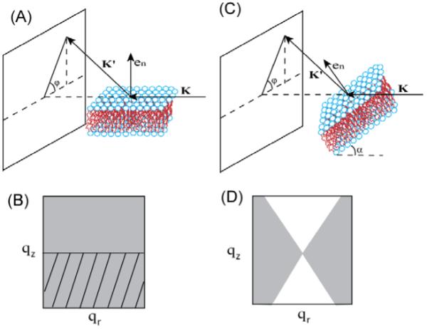
(A) Grazing incident scattering and (C) transmission scattering experimental setup. K is the incident beam, K’ is the scattered beam, en is the normal to the bilayer tilted by angle α from the incident beam in (C). The gray regions in (B) and (D) represent the available reciprocal space corresponding to (A) and (C), respectively. The tilted lines in (B) indicate the region cut off by the silicon substrate.
Data Analysis
The theoretical scattering intensity induced by peptide bundles embedded in lipid bilayers, ignoring the Lorentz factor, is (Guinier 1994)
| (1) |
SP(q) is the structure factor which describes the positional correlation between the peptide bundles.
| (2) |
where Ra and Rb are the central positions of bundles a and b, respectively. Fp(q) in Eq. 1 is the form factor. It is the Fourier transform of the electron density contrast between the peptide bundle and the lipid background (He et al. 1993).
| (3) |
where ρP is the electron density of the peptide and ρL is the electron density of the lipid background. The resulting model intensity IP(q) was fit to the scattering data, allowing the usual constant scaling factor K, by minimizing the residual sum of squares over the data points,
| (4) |
Results and Discussion
I. Peak 1 at low q; Bundles
A. Data
Figure 2 compares the low angle x-ray scattering images for DOPC oriented multilayer samples with and without Alm at similar hydration levels. With no Alm, there is diffuse scattering centered on the meridian (qr=0) that is caused by fluctuations in the bilayer stacking (Liu and Nagle 2004). The addition of Alm causes the appearance of two features centered at qr ≈ ±0.11 Å-1, and in the qz direction it extends up to 0.25 Å-1. Because the membrane is an in-plane fluid, there is only one intrinsic feature and that one is required to occur at symmetrical locations in the qr direction. Although we shall call this feature by the name peak 1, it is most accurately described as a Bragg rod (Als-Nielsen and McMorrow 2001) which is expected when the positions of the scattering entities are not correlated between neighboring membranes in the stack. Bragg rods have also been observed for Alm using neutron scattering (Yang et al. 1999). The Δqz range of the scattering corresponds to uniform scattering entities extending ~25 Å along the normal to the bilayer; this length is consistent with Alm inserted in a transmembrane helix configuration with modest tilting of the ~30 Å long Alm helices (Bak et al. 2001).
Figure 2.
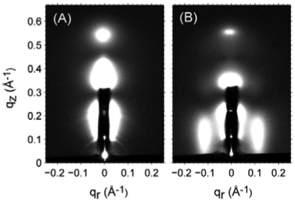
Low angle x-ray scattering (glancing angle α=0.2°) for (A) DOPC and (B) Alm:DOPC 1:10 at similar hydration level (lamellar repeat spacing D≈57 Å). The h=1 (qz=0.11 Å-1 and qr=0) and h=2 (qz=0.22 Å-1 and qr=0) can be seen through the thin molybdenum attenuator that extends to qz=0.32 Å-1.
Features occurring near the same qr have been reported previously using x-ray scattering (Constantin et al. 2007). Because those samples were at much lower hydration, the scattering was more concentrated in q space and resembled diffuse crystal peaks more than the Bragg rod shaped peaks shown in Fig. 2B. We confirm this effect of partial dehydration in part III. Similar side peaks observed by neutron scattering, in D2O for good contrast, have been attributed to water columns formed in the middle of Alm bundles (He et al. 1995). We will base much of our analysis in this section on the barrel-stave model.
We first extract quantitative data for the intensity I1(qr) of peak 1 from the overlapping diffuse lamellar scattering. Following Constantin et al. (2007) the experimental raw data are fit to two Lorentzians, one for the background with center at qr = 0 and the other for I1(qr) with a center at qr1 which is a fitting parameter. Figure 3 shows that the center of peak 1 shifts to smaller qr1 values when the Alm:lipid mole ratio decreases from 1:10 to 1:20. A similar trend was reported for Alm in 1,2-dimyristoyl-sn-glycerol-phosphatidylcholine (DMPC) multilayer samples (Constantin et al. 2007). Other interesting features are that peak 1 becomes wider when the peptide concentration decreases and peak 1 is wider for DOPC than for diC22:1PC. Most importantly, the center peak 1 is at smaller qr1 value for diC22:1PC than for DOPC at the same concentration.
Figure 3.
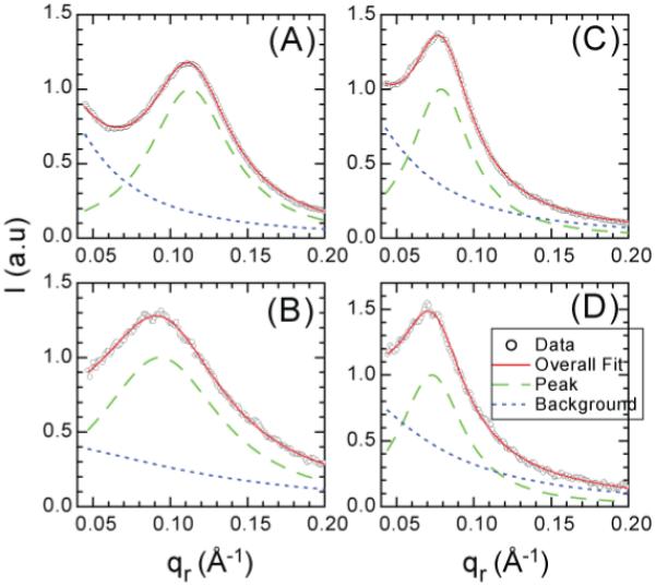
The intensity I(qr) (data points) for each sample was obtained by averaging the data from qz=0.08 to qz=0.12 Å-1 for (A) Alm:DOPC 1:10, (B) Alm:DOPC 1:20, (C) Alm:diC22:1PC 1:10, and (D) Alm:diC22:1PC 1:20. The intensity I1(qr) of peak 1 (dashed green line) was separated from the diffuse scattering Idiffuse(qr) (dotted blue line). The overall scale factor was chosen so that the maximum of I1(qr) =1. The sum of I1(qr) and Idiffuse(qr) is shown as a solid red line close to the data points.
B. Analysis using a cylindrical model for bundles
Figure 4 illustrates a model of a peptide bundle in a lipid bilayer. The bundle is approximated by a hollow cylinder (He et al. 1996) with outside radius b and inside water channel radius a. In Fig. 4 the hydrophobic thickness of the lipid is greater than the height of the bundle, but the opposite leads to similar results. A detailed derivation of the form factor FP(qr, qz) of this model is given in Appendix I. It shows that FP(qr, qz) is insensitive to the inner radius a and results in the approximation
| (5) |
where J1(x) is the first order Bessel function of the first kind and F1(qz) can be approximated by sinc(qzL/2) where L=2Z1 is the length of a uniform cylinder in the z direction.
Figure 4.
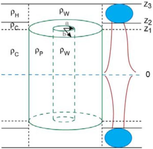
Hollow cylindrical model of an Alm bundle with inside radius a and outside radius b. ρp, ρw, ρc and ρH, are the averaged electron densities of the peptide bundle, water molecules, lipid chain and lipid headgroup region, respectively. The horizontal dashed line in the center indicates the center of the bilayer; z1 indicates the half thickness of the peptide bundle; z2-z1 indicates the remaining lipid chain region above the peptide bundle; z3-z2 indicates the lipid headgroup region.
The second part of the model regards the lateral distribution of the individual bundles in the bilayer. When the hydration level of the Alm/lipid mixture is high, the positional correlation between bundles in different layers is negligible as evidenced by the appearance of Bragg rods and not Bragg peaks, so we only need to consider the distribution of bundles in a single lipid bilayer in order to calculate the structure factor SP(q) (Yang et al. 1999). The scattering intensity due to the peptide is given by Eq. 1. Following (He et al. 1995; He et al. 1996; Constantin et al. 2007) we use a 2-D hard disk model which gives the SP(q) shown in Appendix II. The model requires two parameters, the radius R of the hard disk and the packing fraction η=nπR2/total area, where n is the total number of bundles in the given area. Although it might seem that the radius R of the hard disk should be the same as the outer radius b of the bundle, this resulted in poor fits, so we followed Constantin et al. (2007) by allowing R to be greater than b to account for extended lipid mediated bundle interactions.
Figure 5 shows the fits of the model to peak 1. The parameters b, R and η obtained from fitting the cylindrical model are listed in Table I. By comparing the fitting parameters of the two lipids we see that both the disk radius R and the outside radius b of the peptide bundle are larger for diC22:1PC than for DOPC. The fitting results for the same lipid show that the outer bundle radius b barely changes when the peptide to lipid ratio decreases from 1:10 to 1:20. However, the larger disk radius R increases for both lipids when the peptide to lipid ratio decreases. This is related to the shift in the center qr1 of peak 1 shown in Fig. 3. This change in R is likely an artifact of using a hard core potential to model the lipid mediated interactions which should decrease gradually with distance.
Figure 5.
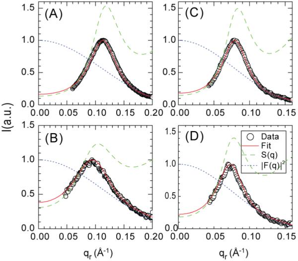
Fits of the cylindrical model to peak 1. The data points are the I1(qr) from Fig. 3. The fitted form factor FP(qr,qz) (dotted blue line), the structure factor (dashed green line) from Eq. A3 and the fitted intensity, Eq. 1 (solid red line) show the results of the best fit for (A) Alm:DOPC 1:10, (B) Alm:DOPC 1:20, (C) Alm:diC22:1PC 1:10, and (D) Alm:diC22:1PC 1:20.
Table I.
Fitting parameters and RSS for the cylindrical model with unperturbed hard disk and perturbed hard disk interactions with fitted U0 and σ parameters
| b(Å) | N | R (Å) | η | U0(kBT) | σ(Å) | RSS | |
|---|---|---|---|---|---|---|---|
| Alm:DOPC 1:10 | 13.3 | 4.9 | 23.5 | 0.42 | -- | -- | 0.29 |
| 13.7 | 5.1 | 23.4 | 0.40 | 1.3 | 29.5 | 0.10 | |
| Alm:DOPC 1:20 | 12.9 | 4.6 | 25.4 | 0.26 | -- | -- | 0.49 |
| 13.6 | 5.1 | 25.9 | 0.20 | 1.3 | 29.5 | 0.38 | |
| Alm:diC22:1PC 1:10 | 18.6 | 8.4 | 33.2 | 0.40 | -- | -- | 0.21 |
| 19.0 | 8.6 | 33.1 | 0.39 | 1.1 | 46.4 | 0.11 | |
| Alm:diC22:1PC 1:20 | 18.7 | 8.4 | 34.7 | 0.33 | -- | -- | 0.50 |
| 19.6 | 9.0 | 35.3 | 0.34 | 1.1 | 46.4 | 0.45 |
Following Constantin et al. (2007) we attempted to make the hard core potential somewhat more realistic by adding a Gaussian repulsive energy G(r)=U0exp(-r2/2σ2) as a perturbation to the hard disk interaction. The structure factor of the perturbed hard disk model is given in Appendix II. The fitting results are listed in Table I. For the same lipid, the parameters of the Gaussian repulsion U0 and σ are fixed to be the same at the two concentrations. This perturbation improves the RSS (Eq. 4) considerably. Although there is a rather small magnitude U0 for the best fitted Gaussian repulsion, the decay length σ is large, consistent with the anticipated potential slowly decaying over a long range. It is also encouraging that the perturbation only changes the values of b by less than one Å. Most importantly, it leaves intact the result that the Alm bundle is larger in diC22:1PC than in DOPC.
Finally, Table I gives values for N, the number of Alm monomers in the bundle. Although this model does not explicitly consider monomers, we estimate N = π/sin-1[r/(b-r)] by assuming that each monomer is a cylinder with radius r= 5 Å with axis parallel to the bilayer normal, and that the monomers touch nearest neighbors around the bundle as in the barrel-stave model. (It may be noted that if the cylinders are tilted by an angle β from the bilayer normal around a horizontal axis from the center of the bundle as indicated by (Bak et al. 2001), then N decreases by a factor of cosβ in order to keep b the same.)
C. Analysis using a molecular dynamics model for bundles
Alm bundles from N=4 to 8 have been simulated at the atomic level in a POPC lipid bilayer (Tieleman et al. 2002) and we have used the atomic coordinates from these simulations as described in Appendix III to obtain the more realistic form factors FP(qr) shown in Fig. 6. We assume that the structure of a bundle that is constrained to have a specific number N of Alm monomers is essentially the same for DOPC and diC22:1PC as it would be for the POPC lipid employed in the simulation. This assumption is quite different from, and much more likely to be valid, than assuming that the most probable number N is independent of the lipid. The fitting procedure is similar to that used for the cylindrical model except that the form factors shown in Fig. 6 were calculated from MD simulations. There are two fitting parameters for each bundle that has N peptides, the disk radius R and the area packing fraction η, both of which are involved in the structure factor SP(qr). Fits of this model to the intensity for DOPC are shown for N=4, 6 and 8 in Fig. 7.
Figure 6.
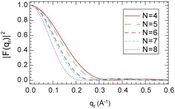
Form factors for Alm MD bundles with N monomers obtained from MD simulations (Tieleman et al. 2002). The sequence of curves is from right to left as N increases from 4 to 8.
Figure 7.

Model fits to Alm:DOPC 1:10 using form factors calculated from MD simulations. (A) N=4, (B) N=6, (C) N=8.
Quantitative fitting results are listed in Table II. For DOPC at both peptide concentrations, the RSS first decreases as N increases from 4 to 6 and then increases as N increases from 6 to 8, indicating that the MD bundle with N=6 fits our data best. The RSS values (0.36 and 0.97 for 1:10 and 1:20, respectively) are comparable to the cylindrical model (0.29 and 0.49) in Table I. For diC22:1PC at both peptide concentrations, the RSS decreases monotonically as N increases from 4 to 8. Although we do not have simulation results for N>8, it is clear that N>8 would fit better. Indeed the RSS for the octamer (1.39 and 2.82 for 1:10 and 1:20, respectively) are large compared to the cylindrical model (0.21 and 0.50). As the difference of the RSS between the pentamer (1.60) and the hexamer (0.36) for Alm:DOPC 1:10 is very similar to the difference between the octamer (1.39) and the best fit of the cylindrical model (0.21) for Alm:diC22:1PC 1:10 (this similarity also applies to Alm:lipid 1:20), this suggests that N=9 might provide the best fit to the scattering data of diC22:1PC. We also note that the cylindrical model gives N=4.8 for DOPC, about ΔN=1.2 smaller than the more realistic MD result. Since the cylindrical model gives N≈8.5, addition of ΔN=1.2 would give N≈9.7 as the best value for diC22:1PC. Note, however, that the best value of N to fit the data need not be an integer as there is likely to be a distribution of N sizes. The smaller N obtained from the cylindrical model fit is related to the fact that its form factor decreases faster than the form factor of the fluffy MD bundle model with the same N. In order to achieve the same decrease in FP(qr), which is needed to fit the data, the cylindrical model needs a smaller b which requires a smaller N.
Table II.
Fitting parameters and RSS obtained using bundles from MD simulations
| N=4 | N=5 | N=6 | N=7 | N=8 | ||
|---|---|---|---|---|---|---|
| Alm:DOPC 1:10 | R (Å) | 24.4 | 24.1 | 23.4 | 23.1 | 22.1 |
| η | 0.43 | 0.42 | 0.42 | 0.42 | 0.44 | |
| RSS | 3.61 | 1.60 | 0.36 | 0.85 | 7.08 | |
| Alm:DOPC 1:20 | R (Å) | 27.0 | 26.6 | 25.0 | 24.3 | 21.0 |
| η | 0.27 | 0.27 | 0.27 | 0.27 | 0.30 | |
| RSS | 6.20 | 2.33 | 0.97 | 2.24 | 12.02 | |
| Alm:diC22:1PC 1:10 | R (Å) | 34.8 | 34.8 | 34.7 | 34.6 | 34.0 |
| η | 0.41 | 0.41 | 0.41 | 0.41 | 0.41 | |
| RSS | 26.37 | 21.29 | 11.48 | 8.64 | 1.39 | |
| Alm:diC22:1PC 1:20 | R (Å) | 37.0 | 37.1 | 37.0 | 37.0 | 36.3 |
| η | 0.38 | 0.38 | 0.38 | 0.38 | 0.37 | |
| RSS | 34.36 | 28.32 | 16.30 | 12.68 | 2.82 |
D. Theory for the effect of different lipids on bundle size
Our best fit in Table II shows that N is ≈6 for DOPC whose hydrophobic thickness 2DC is 26.8 Å. For the thicker lipid bilayer, diC22:1PC, whose hydrophobic thickness 2DC is 34.4 Å, the best fit in Table II shows that N>8. We previously obtained an effective hydrophobic thickness of 27-28 Å for Alm (Pan et al. 2009a). According to the hydrophobic matching mechanism (Killian 1998; Jensen and Mouritsen 2004), when the hydrophobic thickness of the lipid bilayer is larger than the transmembrane (TM) peptides, the lipid bilayer becomes thinner in order to avoid exposure of lipid hydrocarbon chains to water as illustrated in Fig. 8B. The local membrane deformation free energy per unit area has been given as (Huang 1986; Nielsen et al. 1998)
| (6) |
where h is the hydrophobic thickness of the pure lipid bilayer, δh is the local difference in the thickness at position r in the plane of the membrane due to the bundle, KC is the bending modulus, and KA is the area stretch modulus. Our previous study found an average over r of δh = -4 Å in 1:10 Alm:diC22:1PC. Of course, the magnitude of δh for those lipids in close proximity to Alm should be greater than for the average lipid, as is consistent with the larger 7 Å difference in the hydrophobic thickness of Alm and diC22:1PC. In contrast to diC22:1PC, the average δh was less than 1 Å in DOPC, so it is clear that the lipid distortion free energy term in Eq. 6 is much larger for diC22:1PC than for DOPC.
Figure 8.
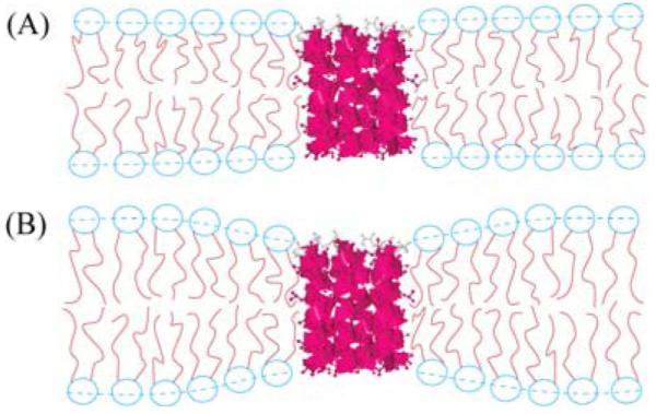
(A) Similar hydrophobic thickness between the lipid bilayer and the peptide bundle. (B) The hydrophobic thickness of the lipid bilayer is larger than the peptide bundle in which case the lipid molecules at the circumference of the peptide bundle deform their molecular shape in order to avoid exposure of hydrocarbon chains to water.
Although the r dependence of the lipid deformation δh can be quite complicated depending upon boundary conditions at the perimeter of the bundle (Nielsen et al. 1998), for convenience, let us approximate it roughly as
| (7) |
where δh(b) is the maximum deformation in those lipids that are next to Alm. The decay range ξ has been given as (Hung et al. 2007).
| (8) |
The area stretch moduli KA for diC22:1PC and DOPC are 263 and 265 mN/m, respectively (Rawicz et al. 2000). The bending moduli KC for diC22:1PC and DOPC are 13 and 8×10-20 J, respectively (Rawicz et al. 2000; Liu and Nagle 2004; Kučerka et al. 2005b; Tristram-Nagle and Nagle 2007; Pan et al. 2008a), and the hydrophobic thicknesses for diC22:1PC and DOPC are 34.4 and 26.8 Å, respectively (Kučerka et al. 2005b; Pan et al. 2008b; Pan et al. 2009b). Therefore, ξ=30 Å in diC22:1 and ξ=23 Å in DOPC. Integrating δh(r) over the plane for a single bundle gives a total deformation volume δh(b)2πξ(ξ+b). Although artificial, it is illuminating to divide by the area/lipid and by δh(b) to obtain nξ = 2πξ(ξ+b)/AL, which would be the number of perturbed lipids if the lipids were represented as two disjoint sets, one of maximally perturbed lipids and the other of lipids not perturbed at all. This gives nξ≈136/bundle in diC22:1PC and nξ≈73/bundle in DOPC, using the b values from Table I. The greater effective number of perturbed lipids nξ in diC22:1PC is another reason the lipid deformation energy is larger than in DOPC.
We next emphasize that the values for the decay lengths ξ for the perturbed lipid are similar to the values of the hard disk radii R for the two lipids given in Tables I and II. This supports the claim that the R values represent lipid mediated interactions between the bundles, provided that it can be shown that such an interaction is repulsive. Naively, one might argue that the interaction is attractive, because bringing two bundles close together decreases the total amount of affected lipid that is in the circles of influence of all the bundles. Disregarding those lipids that are not in two circles of influence, there are only half as many affected lipids when the bundles are close together. However, those lipids that are in the circles of influence of two bundles would, in first approximation, be perturbed twice as much, so their δh2 would be twice as large as the δh1 that the same lipid would have when the bundles are far apart. The first term in the deformation energy in Eq. 6 is proportional to δh2, so the energy of those lipids in the circle of influence of two bundles increases by a factor of four which more than offsets there being only half as many of them as when the bundles are separated. Therefore, the lipid mediated interaction between bundles should be expected to be repulsive, which supports the use of a repulsive interaction in analyzing the data.
We now return to the question of why the larger deformation energy in diC22:1PC leads to bundles with larger N. Integrating Eq. 7 and focusing on the first term in Eq. 6, the total deformation energy per Alm monomer is proportional to ξ[ξ+b(N)] / N=ξ[(ξ+r)+(r/sin(π/N))/N which to order 1/N equals ξ(ξ+r)/N + ξr/π. This shows that the lipid deformation energy decreases monotonically as N increases so it favors large bundles. Of course, N is limited to a finite value because there are other terms in the free energy that increase with increasing N. The most obvious is the translational entropy that decreases as N increases because there are fewer bundles for a fixed concentration of Alm. Another is the interaction of Alm with the water in the center of the barrel-stave bundle. As N increases, the fraction of the Alm surface exposed to water monotonically increases. This decreases the free energy until N becomes large enough that this fraction exceeds the fraction of hydrophilic residues and then this term increases for larger N because hydrophobic residues would have to be exposed to water. Importantly, both these free energy terms that limit N are the same for both lipids, whereas the lipid deformation term that increases N is larger for diC22:1PC. Therefore, the sum of the free energies has its minimal value for larger N for diC22:1PC than for DOPC. This makes the most probable values of N larger for diC22:1PC, consistent with our analysis of our data.
E. Comparison to previous results
Alm bundle size in lipid membranes has also been studied by other groups. Using the same model fitting procedure shown in this paper and similar in-plane scattering induced by the Alm bundle structure at qr≈0.1 Å-1, it has been reported that N ≈ 7 in Alm/DMPC mixtures (Constantin et al. 2007). Because their samples were at a much lower hydration level, their estimated N could have been affected by the correlation between the Alm bundles along the bilayer normal that we treat in Section III. However, the DMPC bilayer is nearly as thick as DOPC, so our value of N=6 for DOPC is in good agreement with the previous DMPC result. Neutron scattering using D2O contrast gave a Bragg rod at qr≈0.1 Å-1 which was used to obtain the radius of the water pore in the middle of the Alm bundle; assuming a barrel-stave model gave N=8-9 in Alm/DLPC and N≈11 in Alm/DiPhyPC (He et al. 1995; He et al. 1996). The hydrophobic core of DLPC bilayer is about 6 Å thinner than the hydrophobic core of Alm (Pan et al. 2009a), which would presumably cause considerable tilt in Alm momoners and that could change the size of the bundle. However, the hydrophobic core of DiPhyPC is close to that of DOPC (Lee et al. 2005), so we have no easy explanation for the larger N value in this lipid. Qian et al. (2008) reported N≈8 in a brominated DSPC bilayer using Fourier transform analysis of the crystal-like peaks obtained in extremely dehydrated conditions. The thickness of DSPC is between that of DOPC and diC22:1PC, so their value of N fits the pattern that N increases with increasing bilayer thickness. Conductance measurements on monoglyceride black lipid membranes prepared in squalene solvent with the hydrocarbon chain sequence 14:1, 16:1, 18:1 and 20:1 were interpreted to give values of N = 2, 3, 7 and 11, respectively (Hall et al. 1984). Their channels were not open at zero voltage and a rather different model involving strongly tilted helices that did not go all the way through the membrane in the off state was used to explain the thickness dependence on N.
II. Peak 2 at high q: Clusters
A. Data
Figure 9 shows the background subtracted wide angle x-ray scattering images for DOPC and for Alm:DOPC 1:10. The comparison shows that the chain wide angle scattering peak at q≈1.4 Å-1 is well preserved when Alm is incorporated into DOPC bilayers. This is very different from a report that another antimicrobial peptide magainin severely decreases the chain wide angle scattering and consequently disrupts the bilayer structure (Münster et al. 2002). Figure 9 also shows that the addition of Alm causes the appearance of two additional peaks. The first one that we have named peak 1 and that has been the focus of Section I is located at qr ≈0.1 Å-1. The second weaker one that we call peak 2 is located at qr ≈0.7 Å-1.
Figure 9.
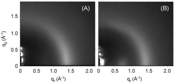
Background subtracted wide angle x-ray scattering images for (A) DOPC and (B) Alm:DOPC 1:10. The narrow black region in the left bottom corner is where a piece of molybdenum attenuator was used to attenuate the direct beam and the lamellar peaks. The broad peak at q ≈1.4 Å-1 is the well known lipid hydrocarbon chain wide angle scattering.
Other peptide concentrations have also been investigated with quantitative results shown in Fig. 10. Even for the pure lipid, there is a shoulder at qr ≈0.7 Å-1 which is likely due to weak correlations between the largely disordered positions of the lipid headgroups (Hub et al. 2007). However, a genuine peak appears with the addition of Alm. The fitting indicated in Fig. 10 suggests that the total background subtracted intensity under the peak is roughly proportional to the concentration of peptide; when a small lipid contribution is subtracted, the ratio of the peak intensities of the 1:10 to the 1:20 samples is 2.4 instead of 2.0.
Figure 10.
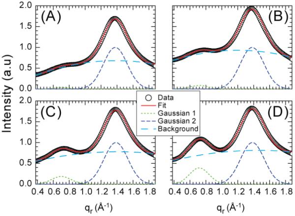
Scattering intensity along the qr direction at qz near zero for Alm:DOPC at ratios, (A) 0:1, (B) 1:75, (C) 1:20, and (D) 1:10. Each data set is fit by the sum of three components: two Gaussian functions representing the two peaks centered at qr ≈0.7 and 1.4 Å-1 and a second order polynomial background. The chain wide angle scattering peak at qr ≈1.4 Å-1 is normalized to 1.0.
B. Origin of peak 2
One hypothesis might be that peak 2 is due to stronger heapgroup correlations induced by Alm. It has been shown that both the electron density distribution of the lipid headgroups and the area/lipid are very little affected by the incorporation of Alm peptides in a DOPC bilayer (Pan et al. 2009a). Together, these suggest that enhanced lipid headgroup correlations are not responsible for the enhanced peak intensity at qr ≈0.7 Å-1.
He et al. (1996) reported a similar peak to our peak 2 in an Alm:DLPC 1:10 sample and interpreted it as originating from the nearest neighbor peptide-peptide packing distance within a bundle. In order to test their hypothesis, we carried out the following analysis. The form factor of an Alm bundle can be expressed by |F(q)|2=|Fmon(q)|2×|Fpos(q)|2, where |Fmon(q)|2 is the form factor of a monomer and |F (q)|2 describes the positional correlation between the peptides within the bundle. Assuming N peptides sit at the vertices of a polygon within the bundle, |Fpos(q)|2 can be calculated as (Constantin et al. 2007):
| (9) |
where d is the distance between each vertex and the polygon center. Figure 11 shows that |Fpos(qr)|2 does have a strong peak at qr ≈ 0.7 Å-1 for the hexamer due to the well defined peptide-peptide distance 2r within the bundle. However, when it is multiplied by the monomer form factor |Fmon(qr)|2 which is calculated from the monomer crystal structure (Fox and Richards 1982), there is no noticeable peak at qr ≈ 0.7 Å-1 because the monomer form factor is very small at large qr values. Furthermore, Fig. 11 shows that the barrel-stave model predicts a peak centered at 0.38 Å-1, primarily due to next nearest neighbor Alm distances in the bundle. This peak should be stronger than peak 2 near 0.7 Å-1. The failure to observe experimentally any peak near 0.38 Å-1 is therefore inconsistent with explaining peak 2 with the barrel-stave bundle model.
Figure 11.
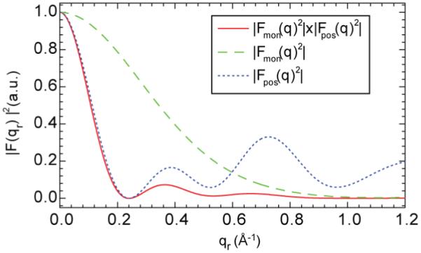
The overall form factor of a barrel-stave bundle with number of peptide per bundle N=6 is shown by the solid red curve. The monotonically decreasing dashed green curve is the form factor for the monomer and the dotted blue curve with a local maximum near qr ≈0.7 Å-1 is the positional factor.
In contrast, we propose that the source of peak 2 is hexagonally packed clusters of Alm with no water channels as illustrated on the left side of Fig. 12. A very large hexagonally packed cluster would have a peak at qr = 2π/2rcos(30°)=0.73 Å-1, where r=5 Å is the radius of the Alm monomer. Although the monomeric form factor would still be very small, the structure factor for an infinite lattice is a delta function. The observed broad width of peak 2 in the qr direction has two likely causes, the finite size of the clusters and positional disorder within each cluster. Both these would also weaken the peak, as observed. An analogy is that the wide angle lipid scattering occurs at roughly twice the qr value because the hydrocarbon chains have roughly half the radius. The difference is that fluid chains have much more orientational disorder, so the wide angle lipid scattering extends much further into the qz direction (Mills et al. 2008). The much more rapid decrease in intensity of peak 2 with increasing qz is consistent with transmembrane Alm helices oriented nearly along the bilayer normal.
Figure 12.
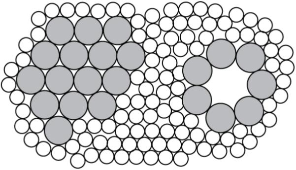
Top view of Alm (large gray circles) packing model in a lipid bilayer (small open circles represent hydrocarbon chains). A hexagonally packed cluster is shown on the left side and a co-existing barrel-stave bundle (N=7) is shown at the right side.
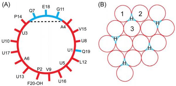
The type of cluster indicated in Fig. 12 is unusual in the Alm literature, although it may be noted that a recent paper combining coarse-grained and all-atom simulations reported that Alm peptides can form large clusters spontaneously (Thøgersen et al. 2008). The usually assumed driving force for barrel-stave bundle formation is that amphipathic helices have a hydrophilic side and a hydrophobic side as shown in Fig. 13A and the bundle forms because the hydrophilic side of each monomer faces the water channel. Of course, amphipathic helices can generally form other structures that do not have a water channel, such as the seven helix transmembrane structure of bacteriorhodopsin. Figure 13B emphasizes that hydophilicity might also be satisfied in an Alm cluster.
Figure 13.
(A) Helical wheel of an Alm monomer obtained from its crystal structure. The dashed line separates the smaller hydrophilic (blue color online) and the larger hydrophobic (red online) faces. (B) The same hexagonally packed cluster in Fig. 12 with hydrophilic strips (blue online) facing each other around the cavities marked by H and with hydrophobic portions (red online) facing other hydrophobic portions or facing the lipid. The motif composed of the three circles numbered with 1, 2, and 3 is the building block for clusters of any size.
A logical question at this point is, can the putative clusters that explain peak 2 also explain peak 1? To address this question, we calculated the internal structure factor of hexagonally packed clusters numerically. An example for a 60-monomer cluster is shown in Fig. 14. There is a strong peak at qr ≈ 0.7 Å-1 due to the Alm packing structure that corresponds to peak 2 in our experiment. Although this peak is narrower in Fig. 14 than peak 2, lateral disorder and smaller clusters would broaden it. There is a strong peak centered at qr = 0 in Fig. 14, but this peak is artifactually high and would be much reduced by employing a minus fluid model for the lipid solvating the clusters, which involves some technical challenges. As the size of the clusters becomes larger, this peak becomes even more confined to qr near zero, and it clearly can not account for peak 1 whose center is at non-zero qr. For 0<q<q2 there are also the familiar ripples that occur from small samples of uniform size; these would be smeared out by the likely dispersion of cluster sizes and their intensity also becomes smaller when the cluster size becomes larger. We therefore believe that clusters can not predict peak 1, but do predict peak 2.
Figure 14.
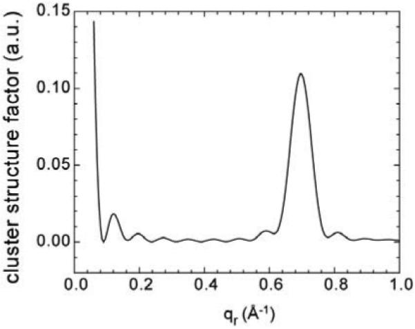
Internal structure factor of a hexagonally packed cluster with 60 Alm monomers.
C. Model for the aggregation of Alm in lipid bilayers
Because peaks 1 and 2 require different structural origins, we now consider a model in which Alm bundles and Alm clusters coexist as shown in Fig. 12. We first note that there also is generally a surface fraction with Alm lying in the plane of the bilayer, but we have previously concluded that the surface fraction is negligible for DOPC and diC22:1PC (Pan et al. 2009a). In this subsection we deduce logical consequences of this model and use our data to test these consequences.
Because the number of monomers would be larger in a cluster than in a bundle, entropic considerations suggest that the ratio of clusters to bundles would increase as the total monomer concentration increased. Unfortunately, when Alm concentration is decreased below 1:20, peak 1, even though it is much more intense than peak 2, is difficult to extract from the very intense diffuse scattering of the lipid bilayer, so there is an insufficient range of concentrations to prove using peak intensities that there are two populations with a non-trivial equilibrium constant. However, our analysis in Fig. 10 found that the ratio of peak 2 to the lipid bilayer wide angle scattering peak increases by a factor of 2.4 instead of a factor of 2 in going from 1:20 to 1:10 Alm:DOPC, indicating that the fraction of Alm in clusters grows more rapidly than the Alm concentration, which is consistent with entropic considerations.
Comparison of the area packing fraction η obtained by fitting in Table II with the mole ratio of Alm to lipid strongly supports our model that Alm is partitioned into bundles and clusters that coexist. The bundle area Abundle=πb2 for different N can be estimated from the MD simulations (Tieleman et al. 2002). It is about 600 Å2 for the hexamer and 1050 Å2 for the octamer (Pan 2009). Assuming that there are only barrel-stave bundles and lipid, the area packing fraction ηB is (Constantin et al. 2007):
| (10) |
where R is the disk radius; N is the number of peptides per bundle; L/P is lipid to peptide ratio; AL is the lateral area per lipid molecule which is 72 Å2 for DOPC and 69 Å2 for diC22:1PC (Kučerka et al. 2005b). The second term in the denominator is the total lipid area per bundle; the number 2 arises because Alm is transmembrane whereas each bilayer is formed by two lipid monolayers. The calculated area packing fractions ηB based on Eq. 10 are listed in Table III. They are considerably larger than the experimental values given as η in Table III using composite values from Tables I and II.
Table III.
Area packing fraction ηB for disks based on Eq. 10 using experimental P/L ratios for each sample, fitted η from Tables II and III, effective (P/L)B for bundles required to obtain ηB=η, and ratio C/B of Alm in clusters to bundles assuming negligible lipid associated with the clusters
| Alm:Lipid P:L | ηB | η | (P/L)B | C/B |
|---|---|---|---|---|
| Alm:DOPC 1:10 | 0.62 | 0.42 | 1:16 | 0.6 |
| Alm:DOPC 1:20 | 0.40 | 0.27 | 1:31 | 0.55 |
| Alm:diC22:1PC 1:10 | 0.95 | 0.41 | 1:28 | 1.8 |
| Alm:diC22:1PC 1:20 | 0.63 | 0.38 | 1:37 | 0.85 |
The discrepancy between η and ηB in Table III means there is at least one incorrect assumption in Eq. 10. It can not be the hard disk radius R or the number of peptides per bundle N as they are related to the structure factor and the form factor which basically determine the position and the width of peak 1. It can not be the bundle radius b either, because it contributes less than 35% to the denominator. The bilayer thickness measurement indicates that with the addition of 10% Alm peptide, the area per lipid differs at most 10% for diC22:1PC and there is negligible difference for DOPC (Pan et al. 2009a). The only adjutable parameter is then the effective peptide to lipid ratio (P/L)B for the bundles. Table III lists the required (P/L)B in order for Eq. 10 to achieve ηB = η and they are all smaller than the experimental P/L. This is consistent with having a substantial fraction of Alm that is not included in bundles and that is included in structures, such as clusters, that have less associated lipid than the bundles. If we assume that the clusters have negligible associated lipid, we can calculate the ratio C/B of Alm in clusters C to Alm in bundles B using (C+B)/L = P/L with B / L=(P/L)B. The last column of Table III shows the ratio C/B. The result that C/B is higher for diC22:1PC than for DOPC is consistent with clusters requiring less adjacent lipid on a per monomer Alm basis, so the greater lipid deformation energy in diC22:1PC favors clusters compared to DOPC. The result that C/B decreases with decreased P/L for both lipids is consistent with the entropic free energy favoring smaller aggregates at low P/L. These results are therefore consistent with our new model in which Alm clusters coexist with Alm bundles.
III. Crystallography of partially dried samples
As stacks of bilayers are partially dehydrated, the water cushion between bilayers becomes thinner and interactions between neighboring membranes become stronger. Figure 15 shows that peak 1 gradually changes from a Bragg rod, appropriate for two-dimensional scattering, to more discrete peaks that indicate three-dimensional correlations. In this section we briefly report our results when we further dehydrated our samples to obtain crystallographic patterns.
Figure 15.
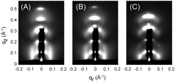
Background subtracted grazing incident scattering images for Alm:diC22:1PC 1:10 at (A) D=64.1 Å, (B) D=61.3 Å, (C) D=58.5 Å.
For this purpose we employed transmission geometry (Fig. 1C) with the result shown in Fig. 16. Although there are broad widths and considerable mosaic spread, six peaks are easily identified. We have indexed these peaks to four possible space groups (Pan 2009). If Alm forms cylindrical bundles, one would suppose that the space group would have an in-plane hexagonal structure and that the Alm would be displaced in neighboring layers either in an ABCABC... stacking pattern (rhombohedral) (Qian et al. 2008) or in an ABAB... stacking pattern (Salditt et al. 2006). However, neither of these space groups predicts peak IV, which is even stronger than peaks II and III. However, all the observed peaks are predicted by a body centered tetragonal (BCT) space group in which the in-plane packing is in a square array with lattice spacing a=37 Å. Neighboring membranes are then located a distance c= 43 Å along the out-of-plane direction, and they have their in-plane square array shifted by a/2 in both in-plane directions. This BCT pattern is not so surprising. If there are repulsive interactions between Alm bundles, both in-plane and between neighboring planes, then there should be a shift of the in-plane array between neighboring planes in order to fit the bundles in one plane into the interstices between the bundles in the neighboring plane. Of course, if there is a high concentration of bundles in each plane, then the in-plane packing must be hexagonal and the best that the neighboring plane can do is to fit into half those small interstices. However, if the concentration is smaller to allow enough room for a square in-plane packing array, then neighboring planes can come closer together and reduce their repulsive interaction energy by a relative shift of the square array of bundles by (a/2,a/2) which neatly places the bundles of one plane into all the interstices of the other plane.
Figure 16.
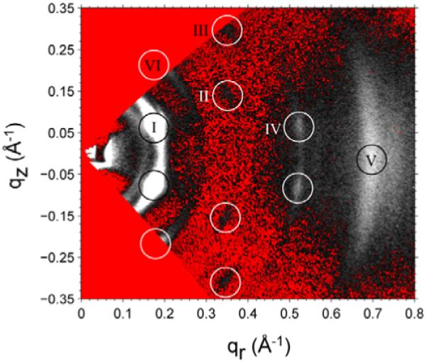
Transmission scattering for Alm:DOPC 1:10 at D=43 Å with sample rotated by α=45° and converted to q-space. The two triangular (red online) regions of q-space, one in the upper left and one in the lower left, touching at q=0, are inaccessible in this transmission geometry. The scattering peaks are indicated by open white circles and are given roman numeral names. Peak VI was observed using α=30°. The white intensities are brightest, and the red (color online) pixels correspond to the smallest intensities after background subtraction. Peaks II and III appear darker than the surrounding background in the non-color figure.
While the BCT space group is clearly better at representing our data than the ABC or AB hexagonal space groups, it is nevertheless worrying that all three space groups allow many peaks that we do not observe. Of course, peaks allowed by space groups may be extinct because of small form factors (usually called structure factors in crystallography), but the number of required extinctions casts some doubt on the BCT assignment. (A full listing of all peaks compatible with these structures is available (Pan 2009).) It may be noted that some of the additional peaks could be indexed to the band of intensity that occurs qr ≈ 0.75 Å-1. Because of the many extinctions, we have also considered a two-dimensional monoclinic space group that has been proposed for protegrin (Yang et al. 2000). This predicts all the observed peaks and requires many fewer extinctions. However, that structure would require ribbons of Alm running uniformly in the y direction in the plane of each horizontal (x,y) layer and such layers would be stacked in the z direction. We find such a structure hard to rationalize, and if it were true, it would be irrelevant to obtaining the structure of the bundle or cluster aggregates that occur in well hydrated samples.
It is clear from the literature that partially dried samples result in different space groups depending delicately upon the conditions of the experiment. Salditt et al. reported the hexagonal AB space group at T=20°C in DMPC bilayers (Salditt et al. 2006), but the observed q range did not include peak IV, so their available data could also be fit with the BCT space group. Qian et al. (2008) also did not obtain data for as large values of qr as ours, but their small qr data clearly did not fit the BCT space group and did fit the rhombohedral ABC space group. Qian et al. (2008) also reported a tetragonal phase at relative humidity from 54 to 58%. We have explored assigning phases to our observed peaks to obtain electron density profiles, but the results are ambiguous, and this is another reason that we are not generally enthusiastic about using partially dried samples to elucidate the structure of Alm aggregates in lipid bilayers.
Summary
Although we do not directly confirm that Alm bundles have the barrel-stave configuration, our modeling of our observed peak 1 is consistent with it. This is the case both for our simple cylindrical model in which the water pore is inessential to our analysis, and for our use of the MD simulations which do contain a water pore. We find that the number N of Alm monomers in the bundle increases when the thickness of the original bilayer increases which is consistent with some previous results, and we explain this as the effect of greater lipid deformation energy in the thicker bilayers. Contrary to a previous conclusion, we do not believe that peak 2 can be explained by barrel-stave bundles. We propose that there are also coexisting clusters (Fig. 12) and this picture is supported by the Alm concentration dependence and by the packing fraction results obtained by fitting to peak 1. Also, crystallographic analysis was applied to partially dried samples and the results lead us to suggest that such samples are not to be preferred for analysis of peptide aggregates in membranes.
Acknowledgments
We thank Prof. Peter Tieleman for providing the MD simulation results of Alm bundles. We acknowledge Dr. Thalia Mills for helping to acquire some of the scattering data at the Cornell High Energy Synchrotron Source (CHESS), which is supported by the National Science Foundation and the National Institutes of Health/National Institute of General Medical Sciences under National Science Foundation award DMR-0225180. This research was supported by NIH Institute of General Medical Sciences Grant GM44976 (PI-JFN).
Appendix I: Form factor of a hollow cylindrical bundle
The form factor of a hollow cylindrical bundle model embedded in lipid bilayer shown in Fig. 4 in the text can be calculated as:
| (A1) |
The electron density is ρp≈0.4 e/Å3 for Alm peptide (Pabst et al. 2007), ρC≈0.3 e/Å3 for hydrocarbon chains, ρW=0.33 e/Å3 for water molecules at 30°C. Because the headgroup region is composed of both lipid headgroups (ρ≈0.5 e/Å3) and water molecules with v:v≈1:1, the averaged electron density of the headgroup region is ρH≈0.4 e/Å3.
For a hexamer bundle, b=r/sin(π/6)+ r =15 Å and a= r/sin(π/6)-r =5 Å based on the barrel-stave model (Baumann and Mueller 1974); r=5 Å is the radius of the helical peptide. Figure A1 shows the behavior of bJ1(qrb)/qr and aJ1(qra)/qr at the qr range of 0-0.2 Å-1 which is the fitting range of peak 1. From the figure we see that bJ1(qrb)/qr changes significantly while aJ1(qra)/qr acts almost as a constant as a function of qr and it is small compared to bJ1(qrb)/qr. We also notice that the two terms containing aJ1(qra)/qr in Eq. A1 have opposite signs based on the numerical values of the electron densities which makes their contribution to the overall form factor even smaller. For these two reasons, the two terms containing aJ1(qra)/qr are ignored, then Eq. A1 can be approximated by
| (A2) |
Figure A1.
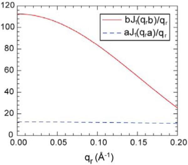
Bessel functions of bJ1(qrb)/qr with b=15 Å and aJ1(qra)/qr with a=5 Å.
Appendix II: Structure factor
The analytical expression of the structure factor for the 2-D hard disk model has been derived in (Rosenfeld 1990) and utilized by (Constantin et al. 2007) to estimate Alm bundle size in DMPC lipid bilayers.
| (A3) |
where η is the area packing fraction of the disks (the area occupied by the disks divided by the total area) and R is the disk radius.
By treating the long range interaction G(r) as perturbation to the hard disk interaction, the perturbed structure factor can be expressed by the following equation based on random phase approximation (RPA) (Hansen and McDonald 1976).
| (A4) |
where S0(q) is the structure factor of the unperturbed state (hard disk interactions), n is the number density of the disks (n=η/πR2), β=1/kBT, and G̃(q) is the Fourier transform of the perturbation G(r).
Appendix III: Form factor calculation for bundles from MD simulations
The main idea of calculating the electron density contrast between the Alm bundle and the lipid background (He et al. 1993) is to select two patches with the same size from a simulation snapshot (Constantin et al. 2007). One contains every atom belonging to the bundle, including water molecules located in the lumen of the bundle, and the other only contains lipid molecules. The form factor can then be calculated by the following equation:
| (A5) |
where rm denotes the position of the mth atom within the bundle patch with electron number Qm and rn denotes the position of the nth atom within the lipid patch with electron number Qn. In practice, we chose two circular patches, one for the bundle and the other for the lipid. The radius of the circular patch varies from 16 to 19 Å in order to include all atoms belonging to the bundle within the patch as N varies from 4 to 8. As the size of the simulation box parallel to the bilayer surface is only 62×55 Å2, for large N (7 and 8), the simulation snapshot needs to be tiled to a 2×2 grid in order to obtain large enough patches. This is valid because the MD simulation itself applied periodic boundary conditions. The other issue concerning the MD bundles is the fixed orientation of the bundle in one snapshot; for our 2-D fluid like samples, the orientation of the bundle is in-plane isotropic. In order to account for this difference, a rotational average around the bilayer normal was carried out when calculating the form factor.
Appendix IV: Hydration effect
Figure A2 shows the peak 1 intensity along the qz direction centered at qr ≈ 0.08 Å-1 at six different lamellar repeat spacings D for Alm:diC22:1PC 1:10. An interesting feature due to the hydration effect is that as the D spacing increases from 63.4 to 70.3 Å, the normalized intensity within the qz range of 0.12-0.22 Å-1 does not change at all while the intensity at qz<0.11 Å-1 decreases continuously. The latter is mainly due to the absorption by the increased water layer thickness between lipid bilayers. This means once the D spacing reaches 63.4 Å for Alm:diC22:1PC 1:10 where the intensity versus qz plot becomes very smooth (no sharp peaks in the plot), the 3-D correlation of the Alm bundles is no longer obvious. The absence of the correlation between the Alm bundles along the bilayer normal simplifies the model we need to calculate the structure factor from a 3-D space to a 2-D space.
Figure A2.
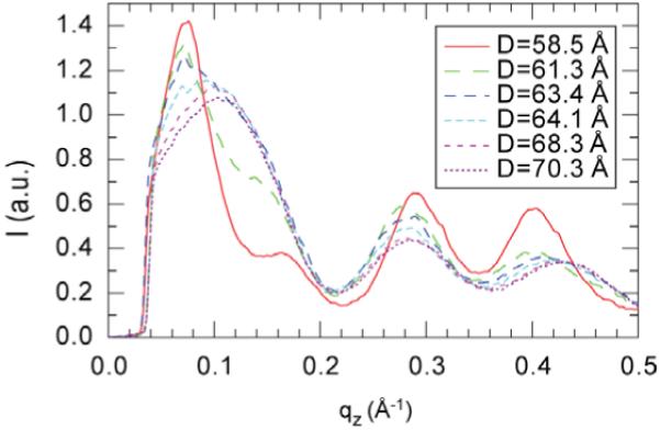
Peak 1 intensity along the qz direction centered at qr ≈ 0.08 Å-1 for Alm:diC22:1PC 1:10.
References
- Als-Nielsen J, McMorrow D. Elements of modern x-ray physics. 2001 [Google Scholar]
- Andersen OS, Koeppe RE. Bilayer thickness and membrane protein function: An energetic perspective. Annu Rev Biophys Biomol Struct. 2007;36:107–130. doi: 10.1146/annurev.biophys.36.040306.132643. [DOI] [PubMed] [Google Scholar]
- Bak M, Bywater RP, Hohwy M, Thomsen JK, Adelhorst K, Jakobsen HJ, Sorensen OW, Nielsen NC. Conformation of alamethicin in oriented phospholipid bilayers determined by n-15 solid-state nuclear magnetic resonance. Biophysical Journal. 2001;81:1684–1698. doi: 10.1016/S0006-3495(01)75822-5. [DOI] [PMC free article] [PubMed] [Google Scholar]
- Baumann G, Mueller P. A molecular model of membrane excitability. Journal of Supramolecular Structure. 1974;2:538–557. doi: 10.1002/jss.400020504. [DOI] [PubMed] [Google Scholar]
- Baumgart T, Hess ST, Webb WW. Imaging coexisting fluid domains in biomembrane models coupling curvature and line tension. Nature. 2003;425:821–824. doi: 10.1038/nature02013. [DOI] [PubMed] [Google Scholar]
- Brown MF. Modulation of rhodopsin function by properties of the membrane bilayer. Chemistry and Physics of Lipids. 1994;73:159–180. doi: 10.1016/0009-3084(94)90180-5. [DOI] [PubMed] [Google Scholar]
- Cafiso DS. Alamethicin: A peptide model for voltage gating and protein-membrane interactions. Annu Rev Biophys Biomol Struct. 1994;23:141–165. doi: 10.1146/annurev.bb.23.060194.001041. [DOI] [PubMed] [Google Scholar]
- Cantor RS. Lateral pressures in cell membranes: A mechanism for modulation of protein function. Journal of Physical Chemistry B. 1997;101:1723–1725. [Google Scholar]
- Constantin D, Brotons G, Jarre A, Li C, Salditt T. Interaction of alamethicin pores in dmpc bilayers. Biophysical Journal. 2007;92:3978–3987. doi: 10.1529/biophysj.106.101204. [DOI] [PMC free article] [PubMed] [Google Scholar]
- Fox RO, Richards FM. A voltage-gated ion channel model inferred from the crystal-structure of alamethicin at 1.5-a resolution. Nature. 1982;300:325–330. doi: 10.1038/300325a0. [DOI] [PubMed] [Google Scholar]
- Gruner SM, Shyamsunder E. Is the mechanism of general-anesthesia related to lipid-membrane spontaneous curvature. Annals of the New York Academy of Sciences. 1991;625:685–697. doi: 10.1111/j.1749-6632.1991.tb33902.x. [DOI] [PubMed] [Google Scholar]
- Guinier A. X-ray diffraction in crystals, imperfect crystals, and amorphous bodies. Dover Publications, INC.; New York: 1994. [Google Scholar]
- Hall JE, Vodyanoy I, Balasubramanian TM, Marshall GR. Alamethicin - a rich model for channel behavior. Biophysical Journal. 1984;45:233–247. doi: 10.1016/S0006-3495(84)84151-X. [DOI] [PMC free article] [PubMed] [Google Scholar]
- Hansen JP, McDonald IR. Theory of simple liquids. Academic press. INC.; New York: 1976. [Google Scholar]
- He K, Ludtke SJ, Wu Y, Huang HW. X-ray scattering with momentum transfer in the plane of membrane. Application to gramicidin organization. Biophysical Journal. 1993;64:157–162. doi: 10.1016/S0006-3495(93)81350-X. [DOI] [PMC free article] [PubMed] [Google Scholar]
- He K, Ludtke SJ, Huang HW, Worcester DL. Antimicrobial peptide pores in membranes detected by neutron in-plane scattering. Biochemistry. 1995;34:15614–15618. doi: 10.1021/bi00048a002. [DOI] [PubMed] [Google Scholar]
- He K, Ludtke SJ, Worcester DL, Huang HW. Neutron scattering in the plane of membranes: Structure of alamethicin pores. Biophysical Journal. 1996;70:2659–2666. doi: 10.1016/S0006-3495(96)79835-1. [DOI] [PMC free article] [PubMed] [Google Scholar]
- Huang HW. Deformation free energy of bilayer membrane and its effect on gramicidin channel lifetime. Biophysical Journal. 1986;50:1061–1070. doi: 10.1016/S0006-3495(86)83550-0. [DOI] [PMC free article] [PubMed] [Google Scholar]
- Hub JS, Salditt T, Rheinstadter MC, de Groot BL. Short-range order and collective dynamics of dmpc bilayers: A comparison between molecular dynamics simulations, x-ray, and neutron scattering experiments. Biophysical Journal. 2007;93:3156–3168. doi: 10.1529/biophysj.107.104885. [DOI] [PMC free article] [PubMed] [Google Scholar]
- Hung WC, Lee MT, Chen FY, Huang HW. The condensing effect of cholesterol in lipid bilayers. Biophysical Journal. 2007;92:3960–3967. doi: 10.1529/biophysj.106.099234. [DOI] [PMC free article] [PubMed] [Google Scholar]
- Jensen MO, Mouritsen OG. Lipids do influence protein function-the hydrophobic matching hypothesis revisited. Biochim et Biophys Acta. 2004;1666:205–226. doi: 10.1016/j.bbamem.2004.06.009. [DOI] [PubMed] [Google Scholar]
- Keller SL, Bezrukov SM, Gruner SM, Tate MW, Vodyanoy I, Parsegian VA. Probability of alamethicin conductance states varies with nonlamellar tendency of bilayer phospholipids. Biophysical Journal. 1993;65:23–27. doi: 10.1016/S0006-3495(93)81040-3. [DOI] [PMC free article] [PubMed] [Google Scholar]
- Killian JA. Hydrophobic mismatch between proteins and lipids in membranes. Biochim et Biophys Acta. 1998;1376:401–415. doi: 10.1016/s0304-4157(98)00017-3. [DOI] [PubMed] [Google Scholar]
- Kučerka N, Liu Y, Chu N, Petrache HI, Tristram-Nagle S, Nagle JF. Structure of fully hydrated fluid phase dmpc and dlpc lipid bilayers using x-ray scattering from oriented multilamellar arrays and from unilamellar vesicles. Biophysical Journal. 2005a;88:2626–2637. doi: 10.1529/biophysj.104.056606. [DOI] [PMC free article] [PubMed] [Google Scholar]
- Kučerka N, Tristram-Nagle S, Nagle JF. Structure of fully hydrated fluid phase lipid bilayers with monounsaturated chains. Journal of Membrane Biology. 2005b;208:193–202. doi: 10.1007/s00232-005-7006-8. [DOI] [PubMed] [Google Scholar]
- Lee MT, Hung WC, Chen FY, Huang HW. Many-body effect of antimicrobial peptides: On the correlation between lipid’s spontaneous curvature and pore formation. Biophysical Journal. 2005;89:4006–4016. doi: 10.1529/biophysj.105.068080. [DOI] [PMC free article] [PubMed] [Google Scholar]
- Liu Y, Nagle JF. Diffuse scattering provides material parameters and electron density profiles of biomembranes. Physical Review E. 2004;69 doi: 10.1103/PhysRevE.69.040901. 040901. [DOI] [PMC free article] [PubMed] [Google Scholar]
- McIntosh TJ, Simon SA. Roles of bilayer material properties in function and distribution of membrane proteins. Annu Rev Biophys Biomol Struct. 2006;35:177–198. doi: 10.1146/annurev.biophys.35.040405.102022. [DOI] [PubMed] [Google Scholar]
- Mills TT, Toombes GE, Tristram-Nagle S, Smilgies DM, Feigenson GW, Nagle JF. Order parameters and areas in fluid-phase oriented lipid membranes using wide angle x-ray scattering. Biophysical Journal. 2008;95:669–681. doi: 10.1529/biophysj.107.127845. [DOI] [PMC free article] [PubMed] [Google Scholar]
- Münster C, Spaar A, Bechinger B, Salditt T. Magainin 2 in phospholipid bilayers: Peptide orientation and lipid chain ordering studied by x-ray diffraction. Biochim et Biophys Acta. 2002;1562:37–44. doi: 10.1016/s0005-2736(02)00357-7. [DOI] [PubMed] [Google Scholar]
- Nielsen C, Goulian M, Andersen OS. Energetics of inclusion-induced bilayer deformations. Biophysical Journal. 1998;74:1966–1983. doi: 10.1016/S0006-3495(98)77904-4. [DOI] [PMC free article] [PubMed] [Google Scholar]
- Pabst G, Danner S, Podgornik R, Katsaras J. Entropy-driven softening of fluid lipid bilayers by alamethicin. Langmuir. 2007;23:11705–11711. doi: 10.1021/la701586c. [DOI] [PubMed] [Google Scholar]
- Pan J, Tristram-Nagle S, Kučerka N, Nagle JF. Temperature dependence of structure, bending rigidity, and bilayer interactions of dioleoylphosphatidylcholine bilayers. Biophysical Journal. 2008a;94:117–124. doi: 10.1529/biophysj.107.115691. [DOI] [PMC free article] [PubMed] [Google Scholar]
- Pan JJ, Mills TT, Tristram-Nagle S, Nagle JF. Cholesterol perturbs lipid bilayers nonuniversally. Physical Review Letters. 2008b;100 doi: 10.1103/PhysRevLett.100.198103. 198103. [DOI] [PMC free article] [PubMed] [Google Scholar]
- Pan JJ. Ph.D thesis. Physics. Carnegie Mellon University; Pittsburgh: 2009. Supramolecular organization of the antimicrobial peptide alamethicin in fluid membranes. [Google Scholar]
- Pan JJ, Tieleman DP, Nagle JF, Kučerka N, Tristram-Nagle S. Alamethicin in lipid bilayers: Combined use of x-ray scattering and md simulations. Biochim et Biophys Acta. 2009a;1788:1387–1397. doi: 10.1016/j.bbamem.2009.02.013. [DOI] [PMC free article] [PubMed] [Google Scholar]
- Pan JJ, Tristram-Nagle S, Nagle JF. Effect of cholesterol on structural and mechanical properties of membranes depends on lipid chain saturation. Physical Review E. 2009b doi: 10.1103/PhysRevE.80.021931. in press. [DOI] [PMC free article] [PubMed] [Google Scholar]
- Phillips R, Ursell T, Wiggins P, Sens P. Emerging roles for lipids in shaping membrane-protein function. Nature. 2009;459:379–385. doi: 10.1038/nature08147. [DOI] [PMC free article] [PubMed] [Google Scholar]
- Qian S, Wang W, Yang L, Huang HW. Structure of the alamethicin pore reconstructed by x-ray diffraction analysis. Biophysical Journal. 2008;94:3512–3522. doi: 10.1529/biophysj.107.126474. [DOI] [PMC free article] [PubMed] [Google Scholar]
- Rawicz W, Olbrich KC, McIntosh T, Needham D, Evans E. Effect of chain length and unsaturation on elasticity of lipid bilayers. Biophysical Journal. 2000;79:328–339. doi: 10.1016/S0006-3495(00)76295-3. [DOI] [PMC free article] [PubMed] [Google Scholar]
- Rosenfeld Y. Free-energy model for the inhomogeneous hard-sphere fluid in d-dimensions - structure factors for the hard-disk (d = 2) mixtures in simple explicit form. Physical Review A. 1990;42:5978–5989. doi: 10.1103/physreva.42.5978. [DOI] [PubMed] [Google Scholar]
- Salditt T, Li CH, Spaar A. Structure of antimicrobial peptides and lipid membranes probed by interface-sensitive x-ray scattering. Biochim et Biophys Acta. 2006;1758:1483–1498. doi: 10.1016/j.bbamem.2006.08.002. [DOI] [PubMed] [Google Scholar]
- Sansom MS. The biophysics of peptide models of ion channels. Prog Biophys Mol Biol. 1991;55:139–235. doi: 10.1016/0079-6107(91)90004-c. [DOI] [PubMed] [Google Scholar]
- Thøgersen L, Schiøtt B, Vosegaard T, Nielsen NC, Tajkhorshid E. Peptide aggregation and pore formation in a lipid bilayer: A combined coarse-grained and all atom molecular dynamics study. Biophysical Journal. 2008;95:4337–4347. doi: 10.1529/biophysj.108.133330. [DOI] [PMC free article] [PubMed] [Google Scholar]
- Tieleman DP, Hess B, Sansom MSP. Analysis and evaluation of channel models: Simulations of alamethicin. Biophysical Journal. 2002;83:2393–2407. doi: 10.1016/s0006-3495(02)75253-3. [DOI] [PMC free article] [PubMed] [Google Scholar]
- Tristram-Nagle S, Zhang R, Suter RM, Worthington CR, Sun WJ, Nagle JF. Measurement of chain tilt angle in fully hydrated bilayers of gel phase lecithins. Biophysical Journal. 1993;64:1097–1109. doi: 10.1016/S0006-3495(93)81475-9. [DOI] [PMC free article] [PubMed] [Google Scholar]
- Tristram-Nagle S. Preparation of oriented, fully hydrated lipid samples for structure determination using x-ray scattering. Humana Press; Totowa, NJ: 2007. [DOI] [PMC free article] [PubMed] [Google Scholar]
- Tristram-Nagle S, Nagle JF. Hiv-1 fusion peptide decreases bending energy and promotes curved fusion intermediates. Biophysical Journal. 2007;93:2048–2055. doi: 10.1529/biophysj.107.109181. [DOI] [PMC free article] [PubMed] [Google Scholar]
- Woolley GA, Wallace BA. Model ion channels: Gramicidin and alamethicin. Journal of Membrane Biology. 1992;129:109–136. doi: 10.1007/BF00219508. [DOI] [PubMed] [Google Scholar]
- Yang L, Harroun TA, Heller WT, Weiss TM, Huang HW. Neutron off-plane scattering of aligned membranes. I. Method of measurement. Biophysical Journal. 1998;75:641–645. doi: 10.1016/S0006-3495(98)77554-X. [DOI] [PMC free article] [PubMed] [Google Scholar]
- Yang L, Weiss TM, Harroun TA, Heller WT, Huang HW. Supramolecular structures of peptide assemblies in membranes by neutron off-plane scattering: Method of analysis. Biophysical Journal. 1999;77:2648–2656. doi: 10.1016/S0006-3495(99)77099-2. [DOI] [PMC free article] [PubMed] [Google Scholar]
- Yang L, Weiss TM, Lehrer RI, Huang HW. Crystallization of antimicrobial pores in membranes: Magainin and protegrin. Biophysical Journal. 2000;79:2002–2009. doi: 10.1016/S0006-3495(00)76448-4. [DOI] [PMC free article] [PubMed] [Google Scholar]


