Abstract
A novel hybrid finite element method for modeling the response of passive and active biological membranes to external stimuli is presented. The method is based on the differential equations that describe the conservation of electric flux and membrane currents. By introducing the electric flux through the cell membrane as an additional variable, the algorithm decouples the linear partial differential equation part from the nonlinear ordinary differential equation part that defines the membrane dynamics of interest. This conveniently results in two subproblems: a linear interface problem and a nonlinear initial value problem. The linear interface problem is solved with a hybrid finite element method. The initial value problem is integrated by a standard ordinary differential equation solver such as the Euler and Runge-Kutta methods. During time integration, these two subproblems are solved alternatively. The algorithm can be used to model the interaction of stimuli with multiple cells of almost arbitrary geometries and complex ion-channel gating at the plasma membrane. Numerical experiments are presented demonstrating the uses of the method for modeling field stimulation and action potential propagation.
Index Terms: Field stimulation, transmembrane potential, Laplace equation, interface problem, hybrid finite element method
1. Introduction
Field stimulation of biological cells has a wide range of applications, including gene transfection [1], [2], electrochemotherapy of tumors [3] and cardiac defibrillation [4]. Much of the understanding on how cells respond to external fields is based on theory derived for a single isolated cell. Analytical expressions for an idealized, passive membrane response has been derived for single cells that are spherical, prolate or oblate spheroidal [5]–[10].
In contrast to a single cell, the response of multiple cells in suspension or in tissue to an electric field is less well understood. The induced transmembrane potential inside a multiple cell system depends on not only cell density but also on the arrangement of cells and their positions [11], [12] in the field. Because of the confounding effects of cell size, position, properties and packing, the electric potential distribution of multiple cells can only be studied using numerical methods and computer simulations.
Of the numerical methods currently used to model field stimulation of biological cells, the finite difference method (FDM) is the easiest to implement. Because the FDM uses Cartesian grids to approximate derivatives or equivalent circuit elements, the geometry of interest is often represented as a piecewise rectangular domain. The application of FDM to geometrically complex domains is more challenging [13] and obtaining good accuracy requires very fine grids or the use of special techniques [14], [15]. In contrast, the finite element method (FEM) [11], [12], [16] or finite volume method (FVM) [17], [18] is a more flexible approach for modeling field simulation of arbitrarily shaped cells. The FEM partitions the intra- and extracellular spaces into simple elements, such as triangles in two space dimensions (2D) and tetrahedrons in three space dimensions (3D). With elements aligned with the membrane of cells, the FEM usually yields higher order accuracy than the FDM. When the cellular media are assumed to have piecewise homogeneous and isotropic conductivities, the electric potential equation simply reduces to the Laplace’s equation. In this case, the integral based boundary element method (BEM) is applicable [19]–[21]. The BEM only discretizes the cell membrane and thus requires fewer grid nodes compared to FDM, FEM and FVM. As a result, BEM can be very efficient and accurate if it is carefully designed and implemented.
The FDM, FEM and BEM all approximate the partial differential equations (PDE) that describe the continuity and conservation of electric flux and membrane currents. The accuracy and ultimate solution times of the methods depend, in part, on the fineness of the grid. In some implementations of the methods to study field stimulation, the membrane and the gap junctions that electrically connect cells are assumed to have finite thickness [22], requiring fine grids in the membrane regions and smooth transitions of element sizes away from these regions. The tractability of the methods is also affected when the nonlinear ion-channel gating and complex membrane dynamics are included. In these cases, the PDE based numerical methods involve the solution of a boundary value problem with nonlinear and time-dependent boundary conditions at each time instance.
To overcome the difficulties of standard methods, some circuit based numerical methods, such as the equivalent circuit methods (ECM) [23], [24] and the transport lattice method (TLM) [13], [25]–[27], have been recently developed. The ECM introduced by Fear and Stuchly [23] was initially used to model the response of cells connected via gap junctions. The ECM represents the cytoplasm and medium by resistances, which are connected in parallel by membrane impedance, and the membrane is represented by a parallel resistance-capacitance unit. Similar to the FDM, the ECM [24] also uses Cartesian grids but with two levels of resolution: a fine grid is built around the membranes while a coarse grid occupies the major area far away from the membranes.
The TLM is based on spatially distributed transport networks, which are solved by Kirchhoff’s laws to determine the potential distribution. It is essentially a spatial representation of the cell membrane and medium using the ECM, and is equivalent to the FEM in that they both solve complicated PDEs. Taking advantage of circuit solving software tools, the TLM offers a wide range of flexibility and modularity for representing highly nonlinear transport processes such as ion channels, ion pumps and membrane electroporation and heat transport within tissue with perfusion [13], [26].
In this paper, a modification of the classical PDE based numerical methods for field stimulation of biological cells is presented. First, the membrane is assumed to be an interface with zero thickness. Second, the electric flux through the cell membrane is introduced as an additional variable into the PDEs. As will be shown, the introduction of the flux variable decouples the time-dependent boundary conditions from the PDEs and, thus makes it easier to include nonlinear membrane dynamics. It also eliminates the need for matching grids in the extracellular space and intracellular space at the interface. The introduction of the flux variable decomposes the original problem into two much simpler subproblems: a linear time-independent interface problem and a nonlinear space-independent initial value problem. In this approach, the linear interface problem is solved with a hybrid finite element method. The initial value problem is integrated by a standard ordinary differential equation (ODE) solver such as the Euler and Runge-Kutta methods. These two subproblems are solved alternatively during time integration. In this sense, the algorithm is highly modular and avoids the need to directly solve a boundary value problems with nonlinear boundary conditions. Simulation results are presented showing that the method can be used to model cells of arbitrary geometries with complex ion-channel gating.
2. Initial Boundary Value Problem
As shown in Fig. 1(a), the cell membrane Γ is assumed to be an interface that separates the computational domain Ω into an intracellular space Ωi and an extracellular space Ωe. The effective electrical conductivity coefficients (units: mS · cm−1) of the intracellular and extracellular spaces are σi and σe, respectively. The time-dependent intracellular and extracellular potentials (units: mV) are given by Φi ≡ Φi(t, x) and Φe ≡ Φe(t, x), respectively. Here, t and x denotes the temporal and spatial variables.
Fig. 1.
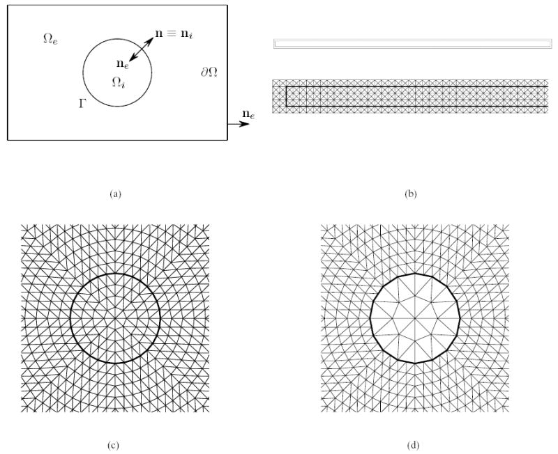
A uniform cylindrical cell fiber: (a) transverse cross-section of the cylindrical fiber in a rectangular domain; (b) longitudinal cross-section of a cylindrical fiber surrounded by a layer of fluids; (c) closeup of a matching triangulation of the intra- and extracellular spaces; (d) closeup of a non-matching triangulation of the intra- and extracellular spaces.
By the conservation of electric flux, the electric potentials Φi and Φe are governed by the second-order elliptic equations:
| (2.1a) |
| (2.1b) |
Here, are the charge (source) density (units: mA/cm3) due to the voltage stimuli applied in the intra- and extracellular spaces. They are nonzero only during the stimulation period and at the positions where the stimuli are applied. In the case that both the intracellular and extracellular spaces have homogeneous and isotropic conductivities, each of the equations (2.1) simply reduces to the Poisson or Laplace’s equation.
Let ni, ne be the unit outward normals to the boundaries ∂Ωe and ∂Ωe of the intracellular and extracellular spaces, respectively. Let n be the unit outward normal pointing outside of a cell on the membrane γ. It is obvious that
As usual, it is assumed that the computational domain Ω is bounded and no-flux boundary conditions are applied on the exterior boundary ∂Ω (see Fig. 1(a)), i.e.,
| (2.2) |
The normal component of the intracellular and extracellular current density at the membrane surface Γ is continuous and equal to the membrane current Im ≡ Im (t, x) (units: mA/cm2), i.e.,
| (2.3) |
The membrane current Im has two components: a capacitive (displacement) current and a resistive (conductive) current. Both the capacitive and the resistive currents depend on the transmembrane potential Vm, which is the difference of the intracellular and extracellular potentials across the membrane, i.e.,
| (2.4) |
Let Cm be the membrane capacitance per unit area (units: μF/cm2) and q be a set of state variables including ion concentrations, which define the physiological state of the cellular structures. Let Iion(Vm, q) be the membrane resistive/ionic current. The membrane current Im is then explicitly given by
| (2.5) |
The state variables q are typically governed by a system of ordinary differential equations:
| (2.6) |
Here, M(Vm, q) is a set of model-dependent functions.
Note that equation (2.4) and the first identity in (2.3) make up two interface conditions for both the potentials and the flux. Thus, a linear interface problem is defined by equations (2.1) subject to the homogeneous Neumann boundary condition (2.2) and the interface conditions. Given transmembrane potential Vm and provided that the cell membrane Γ is smooth enough, the interface problem has a unique solution (Φi, Φe)T , up to an additive constant.
Moreover, by the potential-current relationship (2.3), the membrane current Im can be computed in terms of the solution (Φi, Φe)T to the interface problem. Thus, the membrane current Im is uniquely determined by the transmembrane potential Vm. In this sense, the membrane current Im can be thought of as a linear function of the transmembrane potential Vm, i.e., Im ≡ Im(Vm). Equation (2.5) can then be treated as an ODE for the transmembrane potential Vm in the following form:
| (2.7) |
Given appropriate initial values for the transmembrane potential Vm and the state variables q, the ODEs (2.6)–(2.7) has a unique solution. The overall initial boundary value problem for the electric potential distribution in a cellular structure is thus well-posed.
3. Hybrid Variational Formulation
Let H1(Ωi) and H1(Ωe) be the Sobolev spaces consisting of up to first-order derivatives square-integrable functions on the bounded domains Ωi and Ωe, respectively. Let H1/2(Γ) be the trace space of the Sobolev space H1(Ωi) or H1(Ωe) on the membrane Γ. Let H−1/2(Γ) be the dual space of the trace space H1/2(Γ) [28].
Multiplying each of the Poisson equations (2.1) by a corresponding test function Ψi εH1(Ωi) or Ψe εH1(Ωe), using the technique of integration by parts, and imposing the no-flux boundary condition (2.2) on the exterior boundary ∂Ω yield the following integral identities:
for any test functions Ψi εH1(Ωi) and Ψe εH1(Ωe). Here, λ ɛ − n · σi∇Φi = − n · σe∇Φe denotes the normal component of the flux through the membrane Γ. The interface flux condition (2.3) is naturally incorporated into these two identities.
Note that the intra- and extracellular potentials are coupled by the transmembrane potential through the membrane, which imposes an essential interface condition. To work with the finite element method, the interface condition (2.4) has to be weakly enforced. Multiplied by a test function μ ε M ɛ H1/2(Γ) and integrated over the membrane Γ, the interface condition (2.4) can be expressed as:
for any test function με M.
Furthermore, let X ɛ H1(Ωi) × H1(Ωe)be the product space. Let Ψ = (Ψi, Ψe)T, Φ = (Φi, Φe)T, and σ= diag(σiσe). The interface problem can be equivalently and concisely written in the following variational form: find Φ ε X and λ ε M, such that
| (3.1a) |
| (3.1b) |
for any test functions Ψ ε X and μ ε M . Here, [Ψ] = Ψi − Ψe denotes the jump of the test function Ψ ε X across the membrane Γ. The flux unknown λ is introduced as a variable as well as the potential variables Φi and Φe, which makes the variational problem (3.1) hybrid. In the literature, the flux variable λ is called the Lagrange multiplier and the space M is called the Lagrange multiplier space [29].
The hybrid variational formulation (3.1) makes up a saddle point problem. It has a unique solution (Φ, λ) up to a constant [30]. The solution λ equals the electric flux across the membrane Γ, i.e.,
| (3.2) |
which balances the membrane current Im(Vm) in (2.7).
4. Finite Element Discretization
Let Thi and The be regular triangulations of the intracellular and extracellular spaces with mesh parameters hi and he, respectively. Let Shi and She be the corresponding finite element spaces associated with the partitions. Denote by Xh ɛ Shi × She the finite dimensional subspace of the unconstrained product space X. Here, h = max(hi, he) represents the mesh parameter of the global triangulation Th = (Thi , The). It is important to note that the triangulation Th does not need to be conformal. The two partitions, Thi and The , for the intra- and extracellular spaces, respectively, may be non-matching on the membrane Γ(see Fig. 1(d)). In this case, the membrane can inherit its partition ThΓ from either Thi or The . The corresponding finite element method is called the mortar finite element method [31]–[33]. Let Wh be the trace space of one of the finite element spaces Shi and She on the membrane Γ. Let Mh be the dual space of the trace space Wh. Corresponding to its continuous counterpart, the dual space Mh is called the discrete Lagrange multiplier space.
The discrete version of the variational problem (3.1) reads as follows: find Φh ε Xh and λ ε Mh, such that
| (4.1a) |
| (4.1b) |
for any test functions Ψh εXh and μh ε Mh. In general, especially when the intra- and extracellular grids Thi and The are not matching along the membrane Γ, the finite dimensional spaces Xh and Mh have to satisfy a stability condition in order for the hybrid variational problem to be uniquely solvable (up to a constant) [30]. For the situations where the grids match on the membrane (see Fig. 1(c)), the stability condition is always satisfied by the spaces Xh and Mh introduced above and so is the unique solvability of the discrete variational problem guaranteed as long as the membrane Γ is smooth enough [31].
In matrix-vector notation, the final linear system corresponding to the discrete variational problem has the saddle point form:
| (4.2) |
Here, the block 2 × 2 coefficient matrix is symmetric but indefinite even though the stiffness component A at the top-left corner is non-negative definite. In the literature, a large amount of work has been devoted to the problem of solving such linear systems [34]. For this particular problem, due to the biorthogonality between the nodal basis functions of the finite element trace space Wh and the discrete Lagrange multiplier space Mh, the flux variable λ can be locally eliminated from the saddle point formulation, resulting in a positive definite algebraic system [33]. The linear system is then solved by a standard iterative solver, such as the conjugate gradient iteration method.
5. Algorithm
Assuming that the transmembrane potential Vm and the state variables q have been initialized at t = 0, the algorithm for integrating the electric potential equations (2.1)–(2.7) is formulated as a two-step procedure:
Step 1. With the old transmembrane potential Vm at t = tn = n Δ t, the electric flux λ, which approximates the membrane current Im(Vm), is calculated by solving the linear system (4.2).
Step 2. With the old transmembrane potential Vm, old state variables q at t = tn and the membrane current λ obtained in the previous step, the ODEs (2.6) and (2.7) are integrated by a time step Δt, yielding new values of Vm and q at t = tn+1.
Repeat these two steps above until the final computational time is reached.
6. Test Problem
Analytical solutions are possible for certain geometries and conditions. These solutions can be used to validate the numerical schemes. As in Krassowska and Neu [35], an idealized model of a single cell in an external electric field E, shown in Fig. 2, is considered. The cell is assumed to have a diameter dc that is small compared with the extracellular region and is located far away from the electrodes such that the electric field is approximately uniform in the vicinity of the cell. The extracellular potential far away from the cell corresponds to the uniform electric field:
Fig. 2.
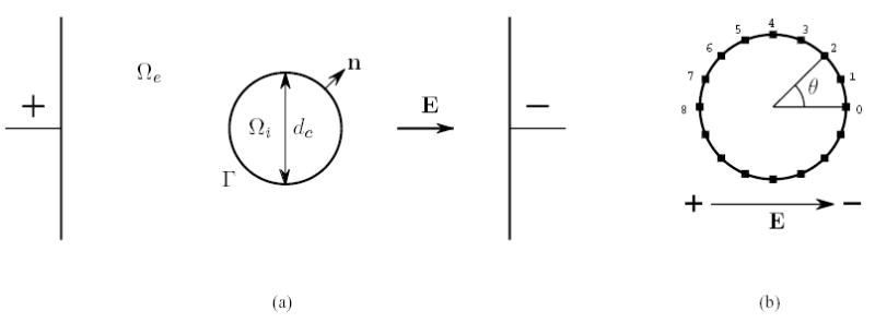
A single circular cell in an external electric field. The electric field E is established by a pair of external electrodes and is assumed uniform in the vicinity of the cell. (a) the space is separated into two parts by the membrane Γ: the intracellular space Ωi and the extracellular space Ωe. Assume that the cell has diameter dc and the unit normal n points from the intracellular to the extracellular space. (b) the marked points are evenly spaced around the circle.
| (6.1) |
Assuming that the membrane is passive, such that the membrane current Iion(Vm, q) = Vm/Rm depends on the transmembrane potential Vm only, the problem corresponds to a cylindrical cell in a transverse electric field. The solution to the problem can be obtained by separation of variables and expressed in cylindrical coordinates as functions of radius r, angle θ and time t as follows:
| (6.2a) |
| (6.2b) |
| (6.2c) |
Here,
The potentials at steady state are given by
7. Computational Considerations
The algorithms for the Hybrid FEM and Delaunay triangulation were implemented in custom codes written in C++. Simulations were all performed on a dual Xeon 3.6 GHz computer. For the test problem of a circular cell with active membrane in a uniform field, the domain comprises approximately 4250 nodes. When the membrane was described with the Hodgkin-Huxley model [36], the simulation required a time step of Δt = 0.015 μs to resolve the dynamics of the very fast early phase and the CPU time per time step was approximately 13.8 ms. Thus for a fixed time step of Δt = 0.015 μs, a simulation of 10.0 ms of activity required approximately 2.5 hrs. The average CPU time per time step scales roughly linearly with the number of nodes.
8. Numerical Results
The hybrid finite element method was applied to several problems of an active or passive cell in an electric field. In all experiments, continuous piece-wise linear finite elements are used to discretize the hybrid variational problem (3.1). The time integration for the ODEs (2.6) and (2.7) simply follows the forward Euler method. The intracellular and extracellular conductivities are σi = 5 mS/cm, σe = 20 mS/cm, respectively. The membrane capacitance is Cm = 1 μF/cm2. For the passive cells, the membrane resistance is Rm = 1 kΩ · cm2. For the active cells, the ionic currents were represented by the Hodgkin-Huxley model [36].
In the first experiment, a passive circular cell with diameter dc = 15 μm is placed between two planar electrodes, with the anode on the left and the cathode on the right (See Fig. 2). The distance between the electrodes, 0.01 cm, is large compared to the cell diameter, so the analytical expression (6.2) can be used for validation. The electric field E = 0.1 V/cm, generated by the planar electrodes, is kept on for the entire duration of the simulation.
Figures 1(c) and 1(d) show the triangular grids used in the simulation. In one case, the grid points on extracellular side of the membrane match with the grid points on the intracellular side of the membrane. The grid on the membrane has a spatial length of approximately Δx = 1.47 μm. In the other case, the grid points on the two sides of the membrane do not match and the membrane inherits the partition from the intracellular space side, which has a coarser triangulation (see Fig. 1(d)). This means the mesh parameter on the membrane in the non-matching case is Δx = 2.94 μm, twice that of the matching case. In both cases, however, the forward Euler Method with a time step Δt = 0.01 μs is used to integrate the ODE (2.7).
Figures 3(a)–(b) show the steady state potentials and the isocontours at time t = 1 μs, respectively. Figures 3(a)–(b) also show the variation of transmembrane potential around the perimeter of the cell (as an exaggerated greyscale strip around cell) and the locations (indicated by small squares) of the peak positive (depolarized) portion (facing the cathode) and peak negative (hyperpolarized) region (facing the anode). The solutions for the matching and non-matching grids are the same, within less than 0.5% error.
Fig. 3.
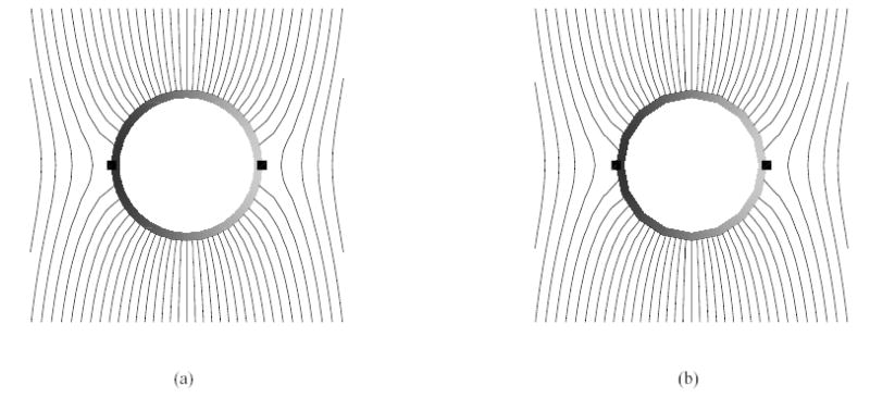
Stimulation across a cylindrical cell with passive membrane. (a) steady state iso-potential contours around the cell with matching grids as shown in Fig. 1(c) (duration the entire simulation, the relative error of the potentials, relative to the maximum transmembrane potential at steady state, is bounded by 2.71 %); (b) steady state iso-potential contours around the cell with nonmatching grids as shown in Fig. 1(d) (during the entire simulation, the relative error of the potentials, relative to the maximum transmembrane potential at steady state, is bounded by 2.94 %).
Figure (4) shows the variation of the intracellular, extracellular and transmembrane potential as a function of time at sixteen evenly spaced points on the circular membrane (see Fig. 2(b)). The computed solutions are compared with the analytic solutions given by Equations (6.2). As is shown, the computed solutions and analytical solutions match very well for all time steps. During the entire simulation, the relative error of the potentials, relative to the maximum transmembrane potential at steady state, is bounded by 2.71 %. Simulations using the non-matching grids at the interface produced nearly identical results. Tables I–II show the relative error bounds at the sixteen points with both matching and non-matching grids at six different times.
TABLE I.
Relative errors of potentials from the simulation with matching grids
| time (μs) | error of Φi | error of Φe | error of Vm |
|---|---|---|---|
| 0.02 | 1.47% | 1.44% | 0.046% |
| 0.05 | 1.57% | 1.56% | 0.043% |
| 0.1 | 1.61% | 1.74% | 0.13% |
| 0.2 | 1.42% | 2.04% | 0.62% |
| 0.5 | 0.56% | 2.53% | 1.97% |
| 1 | 0.050% | 2.71% | 2.64% |
TABLE II.
Relative errors of potentials from the simulation with non-matching grids
| time (μs) | error of Φi | error of Φe | error of Vm |
|---|---|---|---|
| 0.02 | 1.44% | 1.57% | 0.13% |
| 0.05 | 1.41% | 1.73% | 0.32% |
| 0.1 | 1.32% | 1.96% | 0.65% |
| 0.2 | 1.05% | 2.31% | 1.26% |
| 0.5 | 0.37% | 2.78% | 2.41% |
| 1 | 0.025% | 2.94% | 2.89% |
One advantage of the hybrid finite element scheme is that it can be used to model cases in which the membrane has non-linear properties. Another simulation was performed in which the passive membrane was replaced with one whose dynamics were represented by the Hodgkin-Huxley model [36]. The external electric field was increased to E = 5 V/cm to facilitate stimulation since the active membrane model has much larger threshold action potential than the passive one. The intracellular, extracellular and transmembrane potentials at nine points around the cell (see Fig. 2(b)) are plotted in Fig. 5 from 0 to 10 ms. The results are consistent with those given by Krassowska and Neu [35], in which the stimulation process has two distinct phases. In the first phase (Fig. 5), the intracellular, extracellular and membrane potential all show some variation within the first microsecond and then reach a steady state. The results also show that after the initial polarization, all points in the intracellular domain follow the same time course, whereas the extracellular potential is constant in time at a given location.
Fig. 5.
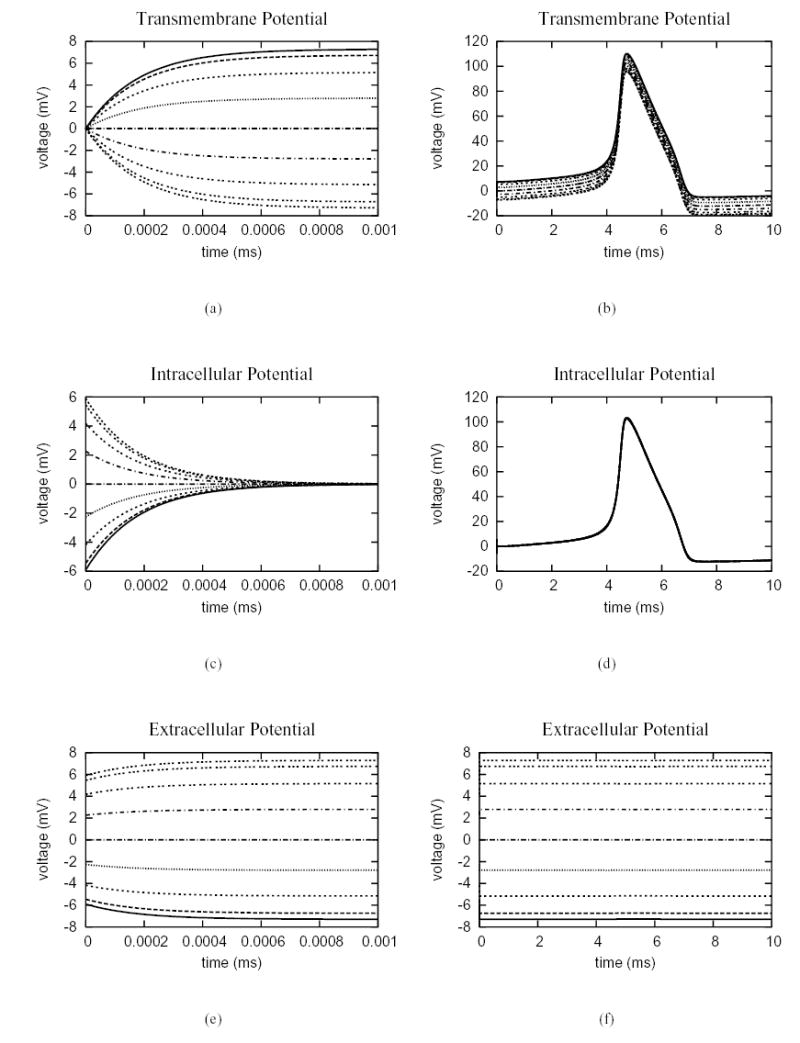
Electric potentials at nine points around the upper semi-circle of the cell shown in Fig. 2(b). The membrane dynamics follows the Hodgkin-Huxley model. (a) from 0 to 0.001 ms and (b) from 0 to 10 ms, the nine lines from top to bottom correspond to the nodes from 0 to 8 in Fig. 2(b). The transmembrane potential has maximum value at node 0, minimum value at node 8 and a value of 0 at node 4; (c) from 0 to 0.001 ms and (d) from 0 to 10 ms, the intracellular potential is spatially uniform at steady state. (e) from 0 to 0.001 ms and (f) from 0 to 10 ms, the nine lines from bottom to top correspond to the nodes from 0 to 8 in Fig. 2(b). The extracellular potential has maximum value at node 8, minimum value at node 0 and a value of 0 at node 4, and is constant in time at steady state.
The response of a passive and active fiber to a re-orientation of the electric field along the long axis of the cylinder was also modeled using the hybrid finite element method. For simplicity, the domain was modeled as a 2D rectangular cross-section of a cylindrical fiber (see Fig. 1(b)) with dimensions 0.2 cm by 15 μm, or 0.4 cm by 15 μm, bounded by a thin layer of fluid with thickness of 5 μm. Figure 6 shows the steady state distribution of the intracellular, extracellular and membrane potentials along the two fibers. For each of the fibers, there is a linear change in extracellular potential and a variation of intracellular potential at two ends corresponding to a hyperpolarization of transmembrane potential at the anode and a depolarization of transmembrane potential at the cathode. These results are consistent with those of Weidmann [37].
Fig. 6.
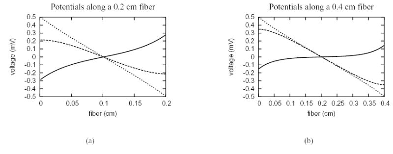
Steady state potential distribution due to field stimulation along uniform cell fibers with passive membrane. The dotted lines mean the extracellular potential, the dashed lines denote the intracellular potential and the solid lines represent the transmembrane potential. (a) the uniform cell fiber has length 0.2 cm. (b) the uniform cell fiber has length 0.4 cm.
Again, the hybrid finite element method can also be used to investigate active and propagated responses. Figure 7 shows the results from the application of both a local (current) stimulus (at one end) and a field (voltage) stimulus along a uniform cell fiber (of length 0.2 cm) with an active membrane described by the Hodgkin-Huxley model. In the first case, a corner at the far end of the fiber is grounded; the local current stimulus with strength 0.2 mA/cm2 is applied at the near end for two microseconds (2 ms). As a result, an electrical wave is initiated at the stimulus site as shown in Fig. 7(a). In the second case, the field stimulation with strength 0.25 V/cm is applied for the entire duration. Because of the short fiber length, both the intracellular and extracellular potentials show variations from classical core conductor predictions [38], [39], in which the potentials are simply scaled versions of the transmembrane potential (with opposite sign) [40]. In the case of field stimulation (Fig. 7(b)), the membrane depolarizes at one end of the fiber and hyperpolarizes at the other end. The depolarized end initiates an action potential that propagates into the hyperpolarized zone. Figure 7(b) shows the intracellular, extracellular and transmembrane potentials along the fiber, demonstrating that the method can be used to study complex interactions of the electric field with active and propagated responses in realistic geometries.
Fig. 7.
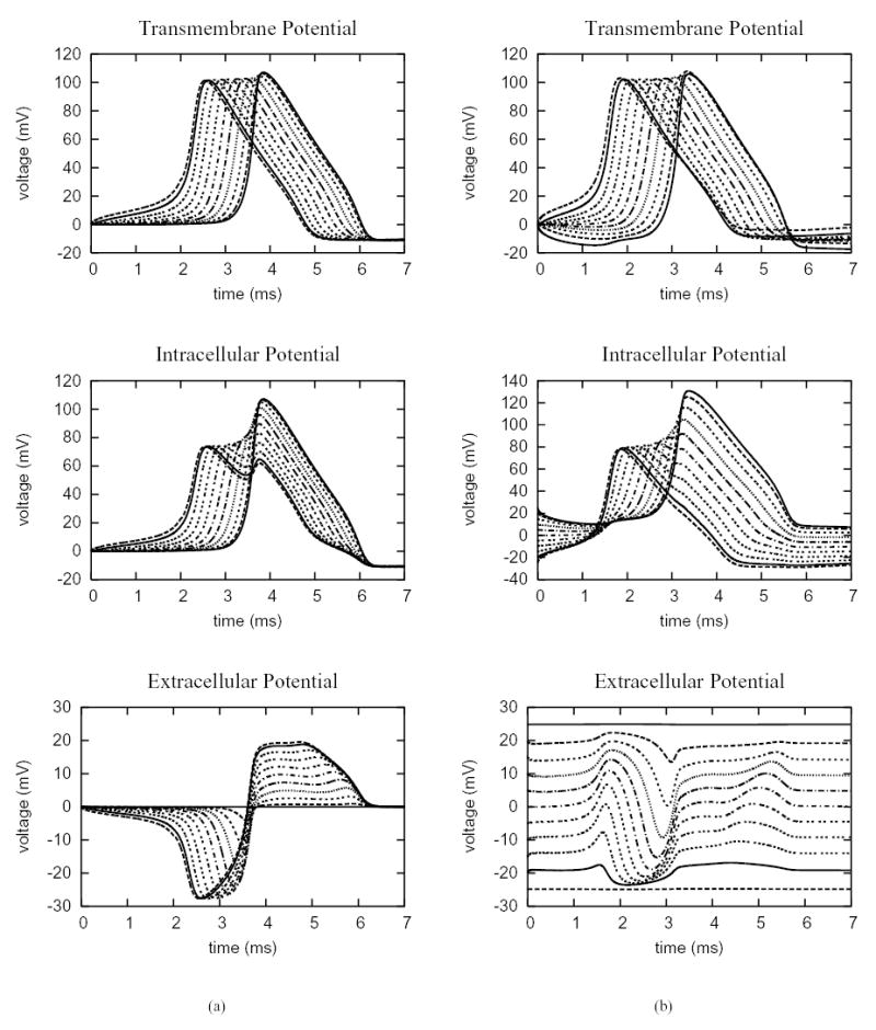
Electric potentials sampled at 11 evenly spaced points along the 0.2 cm uniform cell fiber, which include the endpoints. The membrane dynamics follows the Hodgkin-Huxley model. (a) a current stimulus with strength 0.2 mA/cm2 is applied at the near end of the fiber for 2 ms. (b) a field stimulus with strength 0.25 V/cm is applied for the entire duration of simulation.
Finally, the method was used to consider the response of multiple cells in a uniform electric field. Here, the cells are expected to locally perturb the field. Figure 8 shows closeups of the grids (non-matching) and complex potential distributions for a cluster of 4 circular and elliptical cells. The perturbations of the field act to modify the location of the maximum and minimum transmembrane potentials on the cells (square markers) such that they are not symmetric about the middle axis of the cell as is the case with a single cell. These results clearly show that single cell theory can not be used to predict the response of multiple cells.
Fig. 8.
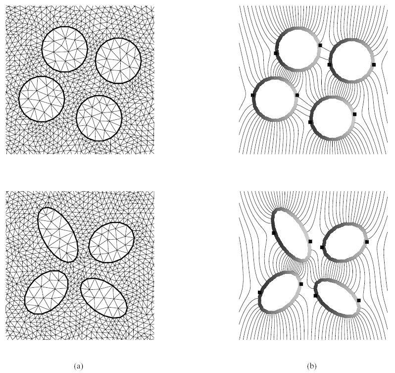
Stimulation of multiple cells under an external electric field (along the horizontal direction): (a) closeup of non-matching triangulations of the intra- and extracellular spaces. (b) steady state iso-potential contours around the cells from the simulation on the non-matching grids that respectively result from uniform refinement of the ones shown in (a) by connecting the midpoints of edges. The square markers denote the local maximum and minimum points of the transmembrane potential, which is defined on the coarse grid side.
9. Discussion
The method proposed in this work provides a powerful and flexible tool for simulating the response of biological cells to an external electric field. In each time step, the algorithm decouples the linear partial differential equations from the nonlinear ordinary differential equations. It not only avoids the need to solve a boundary value problem with nonlinear boundary conditions but also makes the solver highly modularized. The approach makes it straightforward to incorporate various models of membrane ion transport or pore formation [41]–[48]. By similarly introducing the electric flux through gap junctions as an independent variable, the method also can be used to efficiently model the response of assemblies of biological cells connected by gap junctions.
As demonstrated, the hybrid finite element method can be used to model the response in complex domains of multiple cells with arbitrary geometries (see Fig. 8). The introduction of the electric flux variable in (3.1) avoids the need to discretize the thin membrane and provides a more accurate approximation of the membrane current than methods that compute the derivatives of the potential variables. A particular strength of the method is that the intra- and extracellular spaces can be independently partitioned such that the grids do not need to match on the membrane. In some simulations, this will yield some savings in computer resources. In the experiments reported in the work, the intracellular potential inside a cell is typically smoother and has smaller variation. Thus it is more appropriate to use larger elements inside a cell than outside. However, the hybrid finite element method also allows larger elements on the outside of a cell if necessary.
By treating the membrane current as a parameter, a range of ODE solvers can be used depending on the desired accuracy. In the present implementation, only explicit methods such as the forward Euler method and the classic fourth-order Runge-Kutta method are used. Explicit methods have stability restrictions that effect the range of timesteps for the time-dependent problems. To overcome the restriction on timestep size, implicit methods such as the backward Euler, implicit Runge-Kutta methods and backward differentiation formula (BDF) could also be used. A future paper will describe the implementation of the method with adaptive time stepping.
The time spent in solving the space-independent nonlinear ODE part scales linearly with the number of nodes on the membrane. The efficiency of the overall algorithm strongly depends on the linear system solver used for the linear PDE part. In the literature, there are optimal algorithms, such as the multigrid method, which could solve the linear system (4.2) in a work linearly proportional to the number of nodes. In a word, the implementation of the method may be very efficient if an optimal linear system solver is selected for the PDE part.
While the efficiency of the current implementation of the hybrid finite element method can be improved, it can nevertheless be applied to a wide range of problems in biology involving cell-to-cell interactions. The approach is attractive for studying the affect of the extracellular space on current flow during propagation of action potentials, stimulation and field mediated drug delivery. While the results presented were all in two-dimensions corresponding to the response of infinite cylinders in three-dimensions, the response of more realistic cells (e.g. spherical) to an electric field would require a full three-dimensional representation. Fortunately, the method can also be extended straightforwardly to three dimension by using tetrahedral elements instead of triangular elements for the linear interface problem. This extension will make it suitable to study intramural stimulation and impulse propagation in cells of arbitrary shape.
Fig. 4.
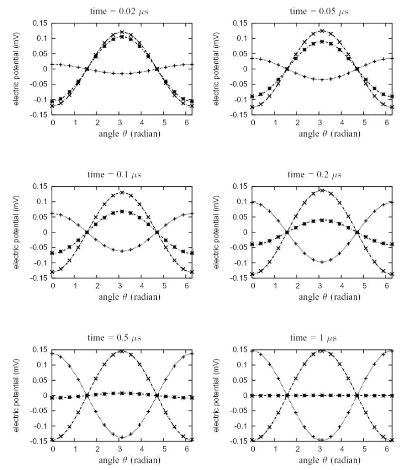
Electric potentials at sixteen evenly spaced points around the cylindrical circle (passive membrane) from the simulation with matching grids (see Fig. 1(c)). The exact solutions are plotted with lines. The numeric data are marked by points. The plus marker “ + ” denotes transmembrane potential, the cross marker “ × ” denotes extracellular potential and the asterisk marker “ * ” denotes intracellular potential. Duration the entire simulation period, the relative error of the potentials at each point, relative to the maximum transmembrane potential at steady state, is bounded by 2.71 %.
Biographies
Wenjun Ying was born in 1976 in Zhejiang, China. He received the B.S. degree and the M.S. degree in Applied Mathematics from Tsinghua University, Beijing, in 1997 and 2000, respectively. He received the Ph.D. degree in Mathematics from Duke University, Durham, NC, in May, 2005. His Ph.D. degree dissertation is on the application of a multilevel adaptive method to modeling electrical wave propagation in the heart.
He currently works as a Research Associate at the Computational Electrophysiology Laboratory in the Department of Biomedical Engineering, Duke University. His research interests include computational electrophysiology, scientific computing and numerical analysis.

Craig S. Henriquez received the B.S.E. degree in biomedical and electrical engineering from Duke University, Durham, NC, in 1981. After teaching high school for two years, he returned to Duke and received the Ph.D. degree in biomedical engineering in 1988.
He became a Research Assistant Professor in 1989 and an Assistant Professor of Biomedical Engineering in 1991 at Duke University. He is currently the Jeffrey N. Vinik Professor of Biomedical Engineering and Computer Science at Duke University. He is also the Co-Director of Duke’s Center for Neuroengineering. His research interests include cardiac and neural electrophysiology, large-scale computer modeling, and neural analysis.

Footnotes
This work was supported in part by NIH grant R01HL76767.
Contributor Information
Wenjun Ying, Department of Biomedical Engineering, Duke University, Durham, NC 27708-0281 USA.
Craig S. Henriquez, Departments of Biomedical Engineering and Computer Science, Duke University, Durham, NC 27708-0281 USA.
References
- 1.Mir LM, Bureau MF, Gehl J, Rangara R, Rouy D, Caillaud JM, Delaere P, Branellec D, Schwartz B, Scherman D. High-efficiency gene transfer into skeletal muscle mediated by electric pulses. Proc Natl Acad Sci USA. 1999;96(8):4262–4267. doi: 10.1073/pnas.96.8.4262. [DOI] [PMC free article] [PubMed] [Google Scholar]
- 2.Neumann E, Kakorin S, Toensing K. Fundamentals of electroporative delivery of drugs and genes. Bioelectrochem Bioenerg. 1999;48(1):3–16. doi: 10.1016/s0302-4598(99)00008-2. [DOI] [PubMed] [Google Scholar]
- 3.Sersa G, Cufer T, Cemazar M, Rebersek M, Zvonimir R. Electrochemotherapy with bleomycin in the treatment of hypernephroma metastasis: case report and literature review. Tumori. 2000;86(2):163–165. doi: 10.1177/030089160008600211. [DOI] [PubMed] [Google Scholar]
- 4.Ashihara T, Yao T, Namba T, Ito M, Ikeda T, Kawase A, Toda S, Suzuki T, Inagaki M, Sugimachi M, Kinoshita M, Nakazawa K. Electroporation in a model of cardiac defibrillation. J Cardiovasc Electrophysiol. 2001;12(12):1393–1403. doi: 10.1046/j.1540-8167.2001.01393.x. [DOI] [PubMed] [Google Scholar]
- 5.Fricke H. The electric permittivity of a dilute suspension of membrane-covered ellipsoids. J Appl Phys. 1953;24:644–646. [Google Scholar]
- 6.Schwan HP. Electrical properties of tissue and cell suspensions. Adv Biol Med Phys. 1957;5:147–209. doi: 10.1016/b978-1-4832-3111-2.50008-0. [DOI] [PubMed] [Google Scholar]
- 7.Kotnik T, Miklavcic D. Analytical description of transmembrane voltage induced by electric fields on spheroidal cells. Biophysical Journal. 2000;79(2):670–679. doi: 10.1016/S0006-3495(00)76325-9. [DOI] [PMC free article] [PubMed] [Google Scholar]
- 8.Gimsa J, Wachner D. Analytical description of the transmembrane voltage induced on arbitrarily oriented ellipsoidal and cylindrical cells. Biophysical Journal. 2001;81(4):1888–1896. doi: 10.1016/S0006-3495(01)75840-7. [DOI] [PMC free article] [PubMed] [Google Scholar]
- 9.Valic B, Golzio M, Pavlin M, Schatz A, Faurie C, Gabriel B, Teissie J, Rols MP, Miklavcic D. Effect of electric field induced transmembrane potential on spheroidal cells: theory and experiment. Eur Biophys J. 2003;32(6):519–528. doi: 10.1007/s00249-003-0296-9. [DOI] [PubMed] [Google Scholar]
- 10.Lee DC, Grill WM. Polarization of a spherical cell in a nonuniform extracellular electric field. Annals of Biomedical Engineering. 2005;33(5):603–615. doi: 10.1007/s10439-005-2397-3. [DOI] [PubMed] [Google Scholar]
- 11.Susil R, Semrov D, Miklavcic D. Electric field induced transmembrane potential depends on cell density and organization. Electro Magnetobiol. 1998;17(3):391–399. [Google Scholar]
- 12.Pavlin M, Pavselj N, Miklavcic D. Dependence of induced transmembrane potential on cell density, arrangement and cell position inside a cell system. IEEE Trans Biomed Eng. 2002;49(6):605–612. doi: 10.1109/TBME.2002.1001975. [DOI] [PubMed] [Google Scholar]
- 13.Stewart DA, Gowrishankar TR, Smith KC, Weaver JC. Cylindrical cell membranes in uniform applied electric fields: validation of a transport lattice method. IEEE Trans Biomed Eng. 2005;52(10):1643–1653. doi: 10.1109/TBME.2005.856030. [DOI] [PubMed] [Google Scholar]
- 14.Peskin CS. Numerical analysis of blood flow in the heart. J Comput Phys. 1977;25:220–252. [Google Scholar]
- 15.LeVeque RJ, Li Z. The immersed interface method for elliptic equations with discontinuous coefficients and singular sources. SIAM J on Num Anal. 1994;31(4):1019–1044. [Google Scholar]
- 16.Semrov D, Miklavcic D. Numerical modeling for in vivo electroporation. In: Jaroszeski MJ, Heller R, Gilbert R, editors. Electrochemotherapy, Electrogenetherapy and Transdermal Drug Delivery: Electrically Mediated Delivery of Molecules to Cells. Totowa, NJ; Humana: 1999. pp. 63–81. [Google Scholar]
- 17.Penland RC, Harrild DM, Henriquez CS. Modeling impulse propagation and extracellular potential distributions in anisotropic cardiac tissue using a finite volume element discretization. Comput Visual Sci. 2002;4:215–226. [Google Scholar]
- 18.Zozor S, Blanc O, Jacquemet V, Virag N, Vesin JM, Pruvot E, Kappenberger L, Henriquez CS. A numerical scheme for modeling wavefront propagation on a monolayer of arbitrary geometry. IEEE Trans Biomed Engr. 2003;50(4):412–420. doi: 10.1109/TBME.2003.809505. [DOI] [PubMed] [Google Scholar]
- 19.Leon LJ, Roberge FA. A new cable model formulation based on Green’s theorem. Ann Biomed Eng. 1990;18(1):1–17. doi: 10.1007/BF02368414. [DOI] [PubMed] [Google Scholar]
- 20.A model study of extracellular stimulation of cardiac cells. IEEE Trans Biomed Eng. 1993;40(12):1307–1319. doi: 10.1109/10.250586. ———. [DOI] [PubMed] [Google Scholar]
- 21.Foster KR, Sowers AE. Dielectrophoretic forces and potentials induced on pairs of cells in an electric field. Biophysical Journal. 1995;69(3):777–784. doi: 10.1016/S0006-3495(95)79951-9. [DOI] [PMC free article] [PubMed] [Google Scholar]
- 22.Fear EC, Stuchly MA. Modeling assemblies of biological cells exposed to electric fields. IEEE Trans Biomed Eng. 1998;45(10):1259–1271. doi: 10.1109/10.720204. [DOI] [PubMed] [Google Scholar]
- 23.A novel equivalent circuit model for gap-connected cells. Phys Med Biol. 1998;43(6):1439–1448. doi: 10.1088/0031-9155/43/6/005. ———. [DOI] [PubMed] [Google Scholar]
- 24.Ramos A, Raizer A, Marques JL. A new computational approach for electrical analysis of biological tissues. Bioelectrochemistry. 2003;59(1–2):73–84. doi: 10.1016/s1567-5394(03)00004-5. [DOI] [PubMed] [Google Scholar]
- 25.Gowrishankar TR, Weaver JC. An approach to electrical modeling of single and multiple cells. Proc Natl Acad Sci USA. 2003;100(6):3203–3208. doi: 10.1073/pnas.0636434100. [DOI] [PMC free article] [PubMed] [Google Scholar]
- 26.Stewart DA, Gowrishankar TR, Weaver JC. Transport lattice approach to describing cell electroporation: use of a local asymptotic model. IEEE Transactions on Plasma Science. 2004;32:1696–1708. [Google Scholar]
- 27.—— Three dimensional transport lattice model for describing action potentials in axons stimulated by external electrodes. Bioelectrochemistry. 2006 doi: 10.1016/j.bioelechem.2005.11.004. (Jan 26, Epub ahead of print). [DOI] [PubMed] [Google Scholar]
- 28.Adams RA, editor. Sobolev Spaces. Academic Press; 1975. [Google Scholar]
- 29.Babuska I. The finite element method with lagrangian multipliers. Numer Math. 1973;20:179–192. [Google Scholar]
- 30.Brezzi F, Fortin M. Mixed and Hybrid Finite Element Methods. New York: Springer–Verlag; 1991. [Google Scholar]
- 31.Huang J, Zhou J. A mortar element method for elliptic problems with discontinuous coefficients. IMA J Numer Anal. 2002;22, M:549–576. [Google Scholar]
- 32.Wohlmuth BI. Discretization methods and iterative solvers based on domain decomposition, ser. Lecture Notes in Computational Science and Engineering. Heidelberg: Springer; 2001. p. 17. [Google Scholar]
- 33.Lamichhane BP, Wohlmuth BI. Mortar finite elements for interface problems. Computing. 2004;72:333–348. [Google Scholar]
- 34.Benzi M, Golub GH, Liesen J. Numerical solution of saddle point problems. Acta Numerica. 2005:1–137. [Google Scholar]
- 35.Krassowska W, Neu JC. Response of a single cell to an external electric field. Biophysical Journal. 1994;66:1768–1776. doi: 10.1016/S0006-3495(94)80971-3. [DOI] [PMC free article] [PubMed] [Google Scholar]
- 36.Hodgkin AL, Huxley AF. A quantitative description of membrane current and its application to conduction and excitation in nerve. Journal of Physiology. 1952;117:500–544. doi: 10.1113/jphysiol.1952.sp004764. [DOI] [PMC free article] [PubMed] [Google Scholar]
- 37.Weidmann S. Electrical constants of trabecular muscle from mammalian heart. J Physiol. 1970;210(4):1041–1054. doi: 10.1113/jphysiol.1970.sp009256. [DOI] [PMC free article] [PubMed] [Google Scholar]
- 38.Clark J, Plonsey R. A mathematical evaluation of the core conductor model. Biophys J. 1966;6(1):95–112. doi: 10.1016/S0006-3495(66)86642-0. [DOI] [PMC free article] [PubMed] [Google Scholar]
- 39.Barr RC, Plonsey R, Johnson CR. Membrane current from transmembrane potentials in complex core-conductor models. IEEE Trans Biomed Engr. 2003;50(4):405–411. doi: 10.1109/TBME.2003.809508. [DOI] [PubMed] [Google Scholar]
- 40.Plonsey R, Barr RC. Bioelectricity: a quantitative approach. Kluwer Academic/Plenum Publishers; 2000. [Google Scholar]
- 41.Neumann E, Sowers AE, Jordan CA. Electroporation and Electrofusion in Cell Biology. Kluwer Academic Pub.; 1989. [Google Scholar]
- 42.Weaver JC. Electroporation: a general phenomenon for manipulating cells and tissues. J Cellular Biochem. 1993;51(4):426–435. doi: 10.1002/jcb.2400510407. [DOI] [PubMed] [Google Scholar]
- 43.DeBruin KA, Krassowska W. Electroporation and shock-induced transmembrane potential in a cardiac fiber during defibrillation strength shocks. Ann Biomed Eng. 1998;26(4):584–596. doi: 10.1114/1.101. [DOI] [PubMed] [Google Scholar]
- 44.Modeling electroporation in a single cell: I. effects of field strength and rest potential. Biophysical Journal. 1999;77(3):1213–1224. doi: 10.1016/S0006-3495(99)76973-0. ———. [DOI] [PMC free article] [PubMed] [Google Scholar]
- 45.Modeling electroporation in a single cell: II. Effects of ionic concentration. Biophys J. 1999;77:1225–1233. doi: 10.1016/S0006-3495(99)76974-2. ———. [DOI] [PMC free article] [PubMed] [Google Scholar]
- 46.Weaver JC. Electroporation of cells and tissues. IEEE Trans Plasma Sci. 2000;28(1):24–33. [Google Scholar]
- 47.Smith KC, Neu JC, Krassowska W. Model of creation and evolution of stable electropores for dna delivery. Biophysical Journal. 2004;86(5):2813–2826. doi: 10.1016/S0006-3495(04)74334-9. [DOI] [PMC free article] [PubMed] [Google Scholar]
- 48.Gowrishankar TR, Esser AT, Vasilkoski Z, Smith KC, Weaver JC. Microdosimetry for conventional and supra-electroporation in cells with organelles. Biochem Biophys Res Commun. 2006;341:1266–1276. doi: 10.1016/j.bbrc.2006.01.094. [DOI] [PubMed] [Google Scholar]


