

Abstract
A compact dedicated 3D breast SPECT-CT (mammotomography) system is currently under development. In its initial prototype, the cone-beam CT sub-system is restricted to a fixed-tilt circular rotation around the patient’s pendant breast. This study evaluated stationary-tilt angles for the CT subsystem that will enable maximal volumetric sampling and viewing of the breast and chest wall. Images of geometric/anthropomorphic phantoms were acquired using various fixed-tilt circular and 3D sinusoidal trajectories. The iteratively reconstructed images showed more distortion and attenuation coefficient inaccuracy from tilted cone-beam orbits than from the complex trajectory. Additionally, line profiles illustrated cupping artifacts in planes distal to the central plane of the tilted cone-beam, otherwise not apparent for images acquired with complex trajectories. This indicates that undersampled cone-beam data may be an additional cause of cupping artifacts. High-frequency objects could be distinguished for all trajectories, but their shapes and locations were corrupted by out-of-plane frequency information. Although more acrylic balls were visualized with a fixed-tilt and nearly flat cone-beam at the posterior of the breast, 3D complex trajectories have less distortion and more complete sampling throughout the reconstruction volume. While complex trajectories would ideally be preferred, negatively fixed-tilt source–detector configuration demonstrates minimally distorted patient images.
1. Introduction
Over the past decade, dual-modality tomographic imaging systems have grown in both clinical and preclinical popularity and offer great promise in the detection and staging of numerous cancerous diseases, monitoring and prediction of treatment therapies and improving precision of surgical biopsies. The main benefit of acquiring 3D transmission and emission data is in the ability to fuse the anatomical framework of an object obtained from a transmission image with an emission image that provides the in vivo localization of the molecular tracer, e.g. in a tumor. Additionally, the transmission data can be used as an attenuation map to compensate the emission data for photon attenuation and absorption by overlapping structures, making the molecular images more quantitatively and spatially accurate. It is anecdotally observed that integrating complementary anatomical and molecular functional information can lead to further improvements in visual quality and quantitative accuracy over independent systems alone (Shreve 2000, Israel et al 2001, Hany et al 2002, Hasegawa et al 2002, Schillaci and Simonetti 2004).
Our lab has been working on developing such a dual-modality single photon emission computed tomography (SPECT) and computed tomography (CT) imaging system specifically dedicated to fully 3D breast imaging (Crotty et al 2005, 2006, Madhav et al 2006). With the compact, high performance gamma camera of the SPECT system (Brzymialkiewicz et al 2006) and the novel quasi-monochromatic x-ray cone-beam of the CT system (McKinley et al 2005b), both systems have independently yielded visualization of small lesions in the breast, especially ones closer to the chest wall. Each system was first developed on its own 3D positioning gantry which permitted simultaneous azimuthal and polar tilting motion capabilities (Brzymialkiewicz et al 2005, McKinley et al 2005a). This allowed the source–detector combinations to be positioned anywhere in a hemisphere about a pendant, uncompressed breast during a tomographic acquisition.
In its initial hybrid integration described here, the SPECT system retains its fully 3D positioning capability. However, the CT system is placed at a fixed-tilt angle and restricted to only a 360° circular rotation around the vertical axis of a pendant breast. Various groups that have developed cone-beam dedicated breast CT tomographic scanners have also been limited to using a circular scan during image acquisition (Chen and Ning 2002, Vedula and Glick 2003, Chen et al 2005, Boone et al 2006). This limits the CT system in its ability to image deep into the breast and chest wall, and introduces insufficient sampling which has previously been shown to be eliminated by using 3D complex acquisition trajectories (Kudo and Saito 1990, Zeng et al 1994, Junhai et al 2003, McKinley et al 2005a, Tornai et al 2005). In this study, we describe the configuration of the dual-modality SPECT-CT system and evaluate the effects on object distortion with the CT system at different stationary tilts. It is necessary to determine if a stationary tilt will (1) permit maximal access to the patient’s breast; and (2) provide sufficiently sampled information.
2. Materials and methods
2.1. Overview of the SPECT-CT system
The first prototype compact dual-modality SPECT-CT system was built (figure 1) for imaging pendant uncompressed breasts (Madhav et al 2006). Both systems, using separate detectors to view an object in the common field-of-view (FOV), rest on a common rotation stage (model RV350CCHL, Newport Corp., Irvine, CA) to allow an azimuthal rotation of 360° around the vertical axis of the breast. The SPECT system is positioned 90° relative to the x-ray source–detector axis. With both systems on the same gantry, the subject is not required to move in between the SPECT and CT acquisitions. A customized patient bed, placed above the hybrid system, is built to allow for patient comfort, shield from scatter x-rays and avoid collision with the equipment below (Crotty et al 2007a).
Figure 1.
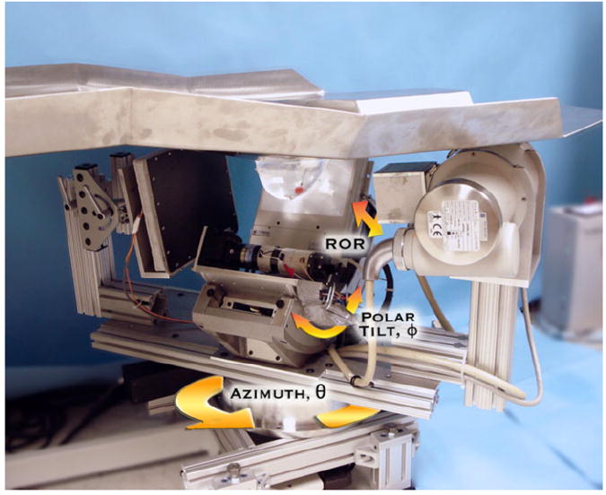
Photograph of the prototype dual-modality dedicated breast imaging tomographic system. The SPECT sub-system (center, back) is placed orthogonally to the x-ray tube (right, front) and digital flat-panel detector (left, toward back). The arrows illustrate system motions (azimuthal, polar and radius of rotation (ROR)). A customized patient bed is located above the hybrid system, shown with a breast phantom pendant through the center opening in the table. Note that the lesion-containing breast phantom is in the common FOV of both systems.
Our current parallel-beam emission tomography system uses a compact 16 × 20 cm2 field-of-view Cadmium Zinc Telluride (CZT) gamma camera (model LumaGEM 3200S™, Gamma Medica, Inc., Northridge, CA) with discretized crystals, each 2.3 × 2.3 × 5 mm3 on a 2.5 mm pitch. The measured energy resolution of the gamma camera at 140 keV is 6.7% FWHM and the collimator sensitivity is 37.9 cps MBq−1 (Brzymialkiewicz et al 2005). Higher energy resolution is the primary reason for using the CZT camera over a scintillator-based camera for the SPECT system. This system has a parallel-hole collimator with hexagonal holes (1.2 mm hole size flat-to-flat, 0.2 mm septa and 25.4 mm height). The camera is attached to a laboratory jack (model M-EL120, Newport Corp., Irvine, CA) and a goniometric cradle (model BGM200PE, Newport Corp., Irvine, CA) permitting various radius of rotations (RORs) and polar tilts (ϕ), respectively.
Our existing cone-beam transmission tomography system uses a rotating tungsten target x-ray source (model Rad-94, Varian Medical Systems, Salt Lake City, UT) with a 0.4/0.8 mm nominal focal spot size and 14° anode angle and a 20 × 25 cm2 FOV CsI(T1)-based amorphous silicon digital x-ray detector (model Paxscan 2520, Varian Medical Systems, Salt Lake City, UT) with a grid size of 1920 × 1536 pixels and 127 μm pitch. Source and detector are secured to the same aluminum plate as the SPECT system. A custom-built collimator is attached to the x-ray source to hold ultra-thick K-edge beam shaping filters to produce a quasi-monochromatic beam (McKinley et al 2005b). The advantages of using a quasi-monochromatic source are (1) improving the visualization of tissues with very small differences in attenuation coefficients; (2) using a low x-ray dose and (3) minimizing beam hardening effect. For these studies, a 60 kVp x-ray beam and a 0.051 cm cerium filter (Z = 58, ρ = 6.77 g cm−3, K-edge = 40.4 keV, Santoku America, Inc., Tolleson, AZ) were used. This filter was approximately a 100th attenuating value layer which reduced the exposure of the incident x-ray beam by a factor of 100 and yielded a spectrum that had a mean energy of approximately 36 keV and the FWHM of 15% (McKinley et al 2004). In the current hybrid setup, the source-to-image distance (SID) is 60 cm and source-to-object distance (SOD) is 38 cm resulting in a magnification of 1.57 for an object located at the center of rotation of the system.
Figure 2 illustrates the current dual-modality SPECT-CT system rotating around a pendant uncompressed breast phantom. As shown in the corresponding polar plot, the SPECT subsystem has fully 3D positioning capabilities while the CT sub-system remains at a fixed polar tilt as the system rotates 360° around the breast. Along with the parallel-beam imaging geometry of the SPECT sub-system, the entire volume of the breast is in the FOV of both systems even at different cone-beam CT tilts (figure 3).
Figure 2.
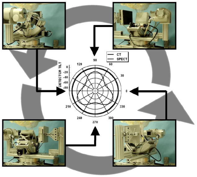
Photographs at different positions of the dual-modality system rotating around a pendant, uncompressed breast and torso phantoms. Polar plot (center) is shown for the SPECT (3D noncircular trajectory) and CT sub-systems (simple fixed-tilt circular orbit).
Figure 3.
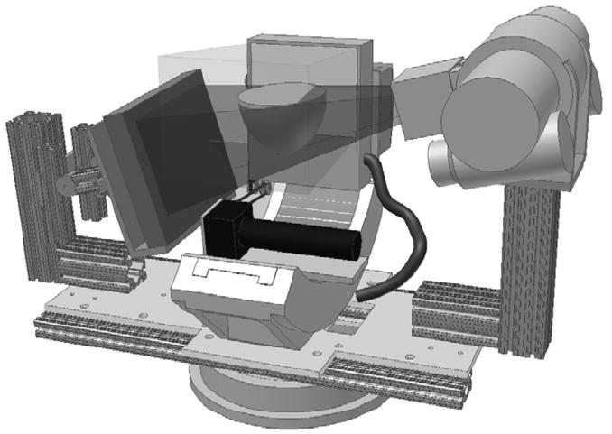
3D CAD model of the SPECT-CT system with a breast placed at the center of rotation. The breast is in the common FOV of both systems regardless of the tilt of the CT sub-system. Translucent volumes illustrate the intersection of both the parallel-beam of the SPECT sub-system and the cone-beam of the CT sub-system.
2.2. Data acquisition
Object visualization, distortion and frequency dependence at different planes of the image volume were measured using a Defrise-type disk phantom (model ECT/MI-DEF/P, 5 mm disk thickness, 5 mm disk spacing, Data Spectrum Corp., Hillsborough, NC) with and without 3.5 mm acrylic balls placed in the interstitial spaces between the disks (figure 4, left). Another measurement utilized a breast phantom consisting of numerous acrylic balls suspended throughout the entire volume. These ‘suspended spheres’ were created by arranging 5 mm diameter acrylic balls on 10 mm center-to-center pitch in a cross pattern on a thin plastic sheet. Each plastic sheet was stretched and glued to the bottom of a circular acrylic frame (20 mm height). These circular bands of varying diameters were stacked together to roughly contour the shape of the breast (figure 4, right). The frames could also be immersed in liquids while retaining the distribution of spheres on a single, nominally attenuating plane. For this set of experiments, five circular concentric frames were placed in a 1050 mL breast phantom shell (nipple-to-chest distance of 11 cm, medial-to-lateral distance of 17 cm and superior–inferior distance of 18 cm). Throughout this paper, each frame of this phantom will be referred to by a number with one representing the circular band with the smallest diameter (nearest the pendant nipple).
Figure 4.
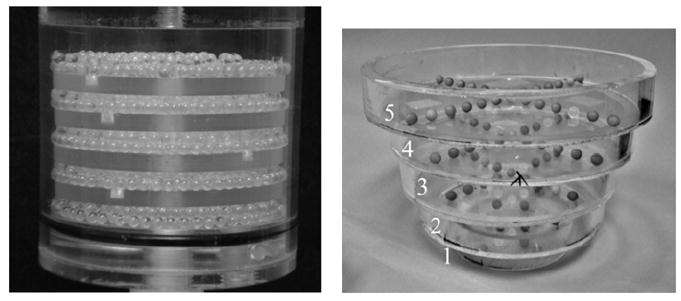
(left) Photograph of the disk phantom with 3.5 mm acrylic beads in the gaps between the disks. (right) Photograph of 5 mm diameter acrylic spheres suspended on thin plastic sheets inside each circular band. Each frame or level is labeled 1 through 5, with 1 being the smallest diameter frame.
Several measurements were taken in air and with the breast uniformly filled with mineral oil to provide different contrasts between the acrylic spheres and breast background. Due to the physical distortion of the breast phantom after filling it with oil (i.e. due to the added weight), only the four smallest annular disks fit in the breast shell. Mineral oil has an intrinsic density of 0.87 g cm−3 and acrylic has a density of 1.19 g cm−3.
Initial measurements were obtained using a simple circular trajectory at 0°, ±5°, ±10° and ±15° fixed polar tilts (figure 5, left), and a saddle trajectory having +15° to −15° ranging polar tilts (figure 5, right). The CT system pivots at the intersection point between the central ray of the cone-beam and center-of-rotation axis. A prior study showed that using a noncircular acquisition orbit (i.e. saddle trajectory) will improve sampling (satisfying Tuy’s data sufficiency condition) and reduce distortion (McKinley et al 2005a). Note that a negative polar tilt is defined as the x-ray source moving up (closer to the patient bed) and the detector moving down (closer to the ground). For ease of acquiring images using the various tilted circular orbits and complex 3D trajectory motion, all acquisitions were taken on the independent CT system which had a 55 cm SID, 35 cm SOD and 1.57 magnification. In this setup, the x-ray source and detector were affixed on their own base plate which rested on top of the goniometer and rotation stage. Similar to the SPECT sub-system on the hybrid device, the goniometer allowed the CT system to be tilted in the polar direction to provide the flexibility to acquire tomographic projection data at various fixed tilted circular orbits and complex trajectories. Tube potential was set at 60 kVp with a 1.25 mAs exposure per projection (McKinley and Tornai 2006). Projection images were collected every 1.5° through a 360° azimuthal acquisition for a total of 240 projections. The total scan time for each acquisition was 6 min. Although the breast is somewhat truncated (seen in figure 5), the suspended sphere phantom was placed in the breast volume such that it was in the center of the field-of-view and not truncated.
Figure 5.
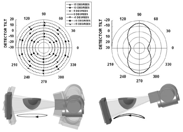
(top) Polar plots for (left) simple tilted circular orbits and (right) 3D saddle trajectory. Polar tilt is defined by the radius of the circle, and the azimuthal angle (location) is defined around the circumference of the circle. (bottom) The 3D CAD drawings of the CT system setup and dark circles underneath are shown to illustrate the location(s) of the source–detector pair during an acquisition. Negative polar tilt is defined as the x-ray detector moving down (or the x-ray source moving closer to the patient bed).
2.3. Patient study
A volunteer with biopsy confirmed breast cancer (adenocarcinoma) in her left breast was imaged with the dedicated breast CT sub-system having a tilted circular orbit, under a protocol approved by the Duke University Medical Center institutional review board (IRB). Informed written consent was obtained.
The subject was scanned with the hybrid system and a customized patient bed. The CT sub-system was at a −6.2° tilt for the entire 360° acquisition. Tube potential was set at 60 kVp with a 1.25 mAs exposure using our standard Ce filtration.
2.4. Image reconstruction and data analysis
Image reconstruction was performed on the CT projection images by increasing the log likelihood via the iterative ordered-subset transmission reconstruction algorithm (OSTR) (Erdogan and Fessler 1999), using a ray-driven image reconstruction code, CT-Map (Bowsher et al 2002), which also accounted for the 3D motion of the CT system (McKinley et al 2005b). Projection images were corrected for gain and offset and binned to 4 × 4 pixels. Reconstruction parameters were set to 5 iterations, 16 subsets, a 350 × 350 × 384 reconstruction grid and a 508 μm3 voxel size. The total reconstruction time in this iterative framework was 4 h.
Object distortion was observed using the sagittal and coronal reconstructed slices of the disk and suspended sphere phantoms collected for all acquisition orbits. Horizontal and vertical line profiles were also drawn through the disks and acrylic balls to compare the differences in image distortion and artifacts for all acquisition trajectories.
3. Results and discussion
3.1. Disk phantom without acrylic balls
The sagittal reconstructed slices of the disk phantom (figure 6) show that the tilted cone-beam acquisition orbits result in disk distortion especially for images acquired at higher positive tilts, where it becomes more difficult to visibly separate out each of the five disks. At some locations in the reconstructed volumes, the apparent positions of the disk and air layer appear to be reversed, a common problem with aliased or highly undersampled tomographic data. Tuy’s data sufficiency condition states that for cone-beam imaging, each plane crossing the object must intersect the orbit of the focal point at least once (Tuy 1983, Smith 1985). Due to the failure to meet this condition with a wide cone-beam, reconstruction of slices for locations further away from the flat plane of the beam (which is parallel to the ground and intersects the focal point) contains significant distortion and errors. This incompleteness in circular trajectories with cone-beam acquisitions has been seen to degrade the reconstructed images, especially with the use of large cone angles (Webb et al 1987, Kudo and Saito 1990, Davis 2005, McKinley et al 2005a).
Figure 6.
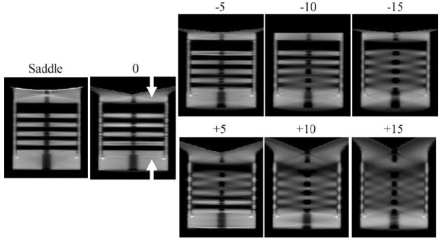
Sagittal reconstructed slices of the disk phantom for 0, ±5, ±10 and ±15, and saddle acquisition trajectories.
Figure 5 (bottom left) illustrates the cause of the insufficient sampling in our experimental setup. When the CT system is at a −10° tilt with the detector positioned down (closer to the ground), the cone-beam is relatively flat near the top of the phantom. This location would be nearer to a patient’s chest wall. Better sampling and minimal disk distortion are seen in the top area of the reconstructed images since these planes intersect the orbit of the vertex of the cone-beam (figure 6, top row). A loss in resolution and inaccuracy in reconstruction are observed when the x-rays travel at a large enough angle that intersects at least two disks. Not surprisingly, the reverse is true for the +10° tilt case, where the insufficient sampling now occurs for slices that are reconstructed from divergent x-rays away from the flat plane at the bottom of the cone-beam (figure 6, bottom row). Due to the large included cone-beam angle of 28°, geometric distortion increases with circular orbits. However, this limitation can be overcome by using a 3D complex acquisition trajectory such as a saddle orbit, which is easily implemented on our independent, 3D CT imaging system. As shown in the reconstructed image slices (figure 6, left), the saddle trajectory can reproduce the object with minimal geometrical distortion due to the improved sampling throughout the object volume.
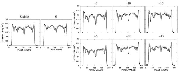
A vertical line profile was obtained for all trajectories semi-quantitatively confirming the disk distortion (figure 7) seen in the earlier reconstructed images (figure 6). The shape of the line profile for the saddle acquisition has a relatively distortion-free and constant attenuation coefficient value through each of the five disks and cylindrical support structure, in contrast to the varying results from the tilted acquisition trajectories. Those other profiles illustrate definite distortion and artifacts especially for planes farther away from the flat, more completely sampled plane of the cone-beam acquisition. These distortions cause the profiles to have a greater variation in the attenuation coefficient value among each of the disks. For instance, in the −10° tilt situation, the profile taken through the disks near the top of the disk phantom is less distorted than the profile taken through the disks further away. Therefore, it is clearly illustrated how complex 3D acquisition trajectories can overcome these cone-beam sampling artifacts, especially for the outer planes of the beam where distortions become more significant.
Figure 7.
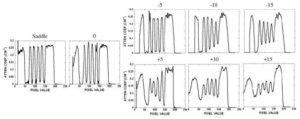
Line profiles obtained vertically through the disks in the disk phantom for all acquisition trajectories. Values indicate degrees of tilt or complex trajectory. Figure 6 indicates the position of the line profile shown between the white arrows.
A horizontal line profile was also drawn across regions of the reconstructed images of the disk phantom (figure 8, right). For the profiles obtained with simple circular orbits, cupping artifacts were observed and became worse at locations further away from the flat horizontal plane of the cone-beam. Cupping artifacts are generally considered to be consisted of scatter and beam hardening in the projection images. Since the disks are virtually suspended in air, scatter is minimal in this experimental setup. Also, the independent dedicated breast CT system uses a quasi-monochromatic beam which virtually eliminates beam hardening (McKinley et al 2005b, Crotty et al 2007b). Therefore, the apparent cupping artifacts are most likely caused by data insufficiency. The profile in figure 8 shows the saddle trajectory having more constant profile values than the other tilted circular acquisition orbits. Using a table of x-ray mass attenuation coefficients, the measured attenuation coefficient of acrylic at 36 keV is 0.30 cm−1 (Hubbell and Seltzer 1996). The line profile shows a reduced attenuation coefficient value primarily due to the presence of scatter. Negative circular acquisition orbits display a slight cupping artifact due to the location of the flat plane of the cone-beam relative to the position of the line profile. A distinct and consistent decrease in attenuation coefficient values at higher positive angle acquisition orbits is observed since this region is in the outer planes (i.e. x-rays at larger angles) of the cone-beam, relative to where the profile was measured.
Figure 8.
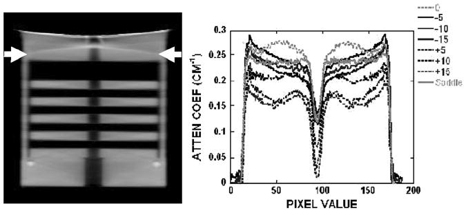
(left) Reconstructed sagittal slice of the disk phantom acquired with the saddle trajectory. (right) Horizontal line profile for all acquisition trajectories. Arrows indicate the position of the profile.
3.2. Disk phantom containing additional acrylic balls
Disk distortion due to undersampling was next examined with the disk phantom uniformly packed with 3.5 mm acrylic beads in the interstitial spaces between each disk. The intent with this modified disk phantom was to evaluate whether there was an object frequency dependence on the reconstructed image results by imaging both the disks and considerably smaller acrylic balls simultaneously. Figure 9 shows a not surprisingly similar disk distortion as seen for the disk-only phantom without the balls. Furthermore, despite the inaccurate reproduction of the disks located further away from the fully sampled plane of the cone-beam, some small acrylic beads can be singled out, and appear to be less distorted in these same areas. The saddle trajectory-acquired data, which clearly illustrate the visualization of all balls in that given slice, can be used as the standard with which to compare all the other acquired and reconstructed data. A line profile through the bottom row of acrylic balls in the phantom confirms that each can be distinctly separated (figure 10). These findings suggest that identifying an amorphous object in reconstructed space partly depends on the distribution of its frequency components (Bartolac et al 2006). In this case, the high frequency and discrete objects (i.e. acrylic balls) remain more preserved than the low-frequency information (i.e. disks). One study has previously shown that data collected with larger cone angles sustained high-frequency details despite the distortion and artifacts associated with cone-beam imaging, while smaller cone angles maintained low-frequency details at the expense of the lower signal-to-noise ratio (Davis 2005). Our results with the dedicated mammotomographic imaging system are consistent with these previous findings. For all tilted orbits, figure 9 shows that the low-frequency information in the disks is preserved around the area of the flat plane of the cone-beam (i.e. small cone angles) while at locations further away (i.e. large cone angles) the high-frequency information of the acrylic spheres is kept regardless of the disk distortion. Not surprisingly, use of the more completely sampling saddle trajectory nearly completely eliminates these sampling-related distortions.
Figure 9.
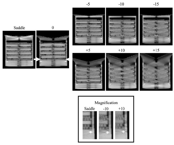
Sagittal reconstructed central slices of the disk phantom containing additional acrylic balls for 0, ±5, ±10 and ±15, and saddle acquisition trajectories. (Bottom) Magnification of a small area of the disk phantom for ±10 and saddle acquisition trajectories to illustrate the visualization of the acrylic balls.
Figure 10.
Horizontal line profile taken through the bottom row of acrylic balls in the disk phantom for all acquisition trajectories. Figure 9 indicates the position of the line profile shown between the white arrows.
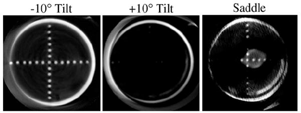
3.3. Suspended spheres in air in the breast phantom
Object distortion was additionally examined in different coronal slices of a breast-shaped phantom with the suspended sphere phantom inside its tiered frame. Horizontal and vertical lines drawn across images of the acrylic balls in the three smallest circular disks (frames 1–3) placed closest to the nipple showed negligible differences among different acquisition trajectories (i.e. fixed tilt or saddle) (figure 11). However, close inspection of the reconstructed coronal slices through each of the annular disks obtained using stationary polar tilt orbits revealed overlapping structures (figure 12). For the −10° tilt cone-beam acquisition, there is nearly complete sampling close to the top slice (near the chest wall) where all objects are more completely sampled and no overlapping (i.e. out-of-plane) structures can be seen there. However, with a negative system tilt, overlapping structures (i.e. from the frame below) become more noticeable in reconstructed slices closer to the nipple (figure 12, top left). Due to the insufficient polar sampling that does not ‘fill in’ additional views of the object in the FOV, out-of-plane information is inaccurately superimposed on any single plane of interest (shown by the white solid arrow in figure 12, top left). The reverse trend is true in the +10° tilt case (figure 12, bottom). However, using the saddle trajectory, there is more complete polar sampling yielding far fewer noticeable artifacts in the reconstructed slices (figure 12, middle column). The line profiles (figure 12, right column) illustrate how out-of-plane object information acquired with an incomplete sampling trajectory can contribute contaminated information into a given plane of interest. With 3D acquisition trajectories, such as saddle, there is more complete sampling of the object volume in the polar and azimuthal directions, resulting in the reduction of overlapping structures originating out-of-plane. Although more of the acrylic balls can be clearly seen when the top of the cone-beam is level (i.e. −10° tilt) near the back of the pendant breast (i.e. near chest wall), complex 3D trajectories overall allow for less distortion and more complete sampling (figure 13).
Figure 11.
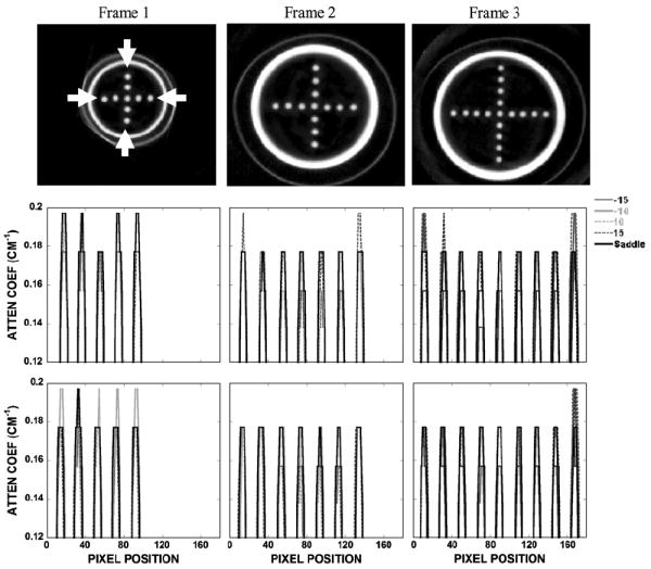
(top) Reconstructed coronal slices of the spheres arranged in a cross pattern acquired with saddle. Outer thin perimeter is the actual breast cup; inner thicker annulus is the acrylic frame supporting the sheet suspending the balls. (middle) Vertical and (bottom) horizontal profiles drawn through the acrylic balls along the directions indicated between the white arrows.
Figure 12.
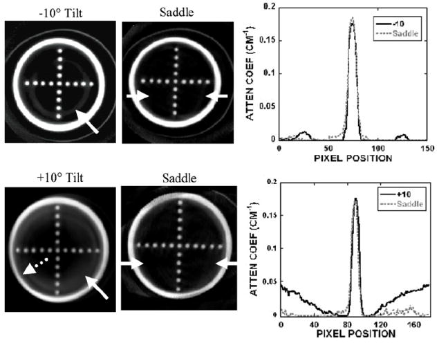
(top left) Reconstructed slice of frame 3 obtained with the −10° tilted orbit. (bottom left) Reconstructed slice of frame 4 obtained with the +10° tilted orbit. Solid arrow illustrates an overlapped region in which the frame below can also be seen in this single slice (shown at the arrow tip). Dotted arrow illustrates the geometric distortion of the acrylic frame. (middle column) Reconstructed slice of the same phantom acquired with the saddle trajectory. (right column) Line profile (obtained from between arrows on the saddle slice) shows some artifacts due to the overlapped regions in the slice acquired with the (top) −10° and (bottom) +10° tilts.
Figure 13.
Reconstructed slice of frame 5 acquired at (left) −10°, (middle) +10° tilt and (right) saddle trajectory. The top plane at the −10° tilt is more uniformly sampled, whereas this frame is out of the FOV for many of the angles with the other two trajectories. Even though more acrylic balls are seen at the −10° tilt, 3D complex trajectories have less distortion and more complete sampling throughout the reconstruction volume.
Profiles drawn over the acrylic balls of frame 4 shown in figure 12, bottom, are illustrated in figure 14. Consistent with the earlier disk measurements (figure 8), the horizontal and vertical profiles also show that there is a cupping artifact with the fixed-tilt orbit by observing the intensities from the edge toward the center, which could be mistaken for scatter or beam hardening. This is missing from the saddle-acquired data due to its more sufficient sampling throughout the imaged volume.
Figure 14.
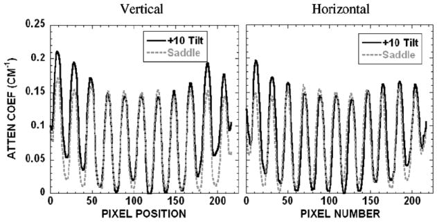
(left) Vertical and (right) horizontal profiles over lesions of frame 4 obtained with the +10° tilt and saddle shown in figure 12, bottom.
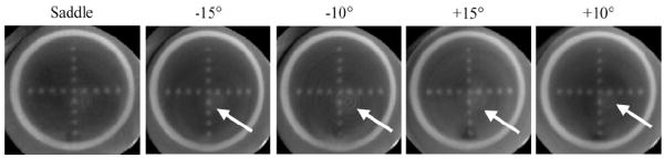
Effects of insufficient sampling were also seen in the reoriented sagittal slices of the breast phantom (figure 15). When the system is at a −10° tilt, there is better sampling at the top of the reconstructed volume compared with the bottom. This is illustrated by the uniformity of the peak heights of the profiles across the FOV. This phenomenon is reversed for the +10° tilt, which again shows a similar cupping artifact as illustrated earlier, in which the plane was located at an extreme edge of the cone-beam. However, while the particular image shows artifacts at the top with a saddle trajectory, line profiles confirm that there is uniformity of signal amplitude through the entire reconstructed volume, for the indicated spheres.
Figure 15.
(top) Sagittal reconstructed slices of the ball phantoms acquired at indicated trajectories. (bottom) Profiles drawn through the ball phantom (bottom left) at frame 2 (indicated in the top-middle image) and (bottom right) at frame 4. Tilt at −10° shows greater peak uniformity at frame 4, while the +10° tilt shows more uniformity at frame 2. Saddle trajectory shows stable peak height uniformity throughout the reconstructed volume.
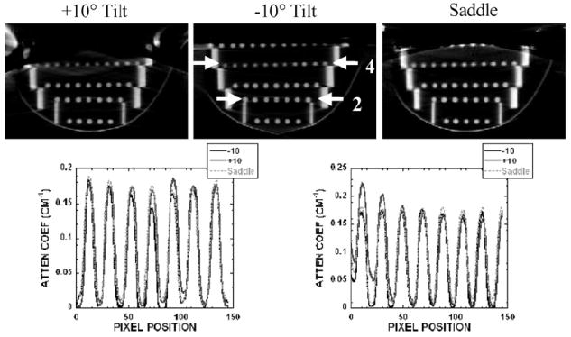
3.4. Suspended spheres in oil in the breast phantom
In order to assess whether these phenomena are visible in lower contrast environment, the breast shell containing the suspended sphere phantom was uniformly filled with mineral oil. Figure 16 shows the reconstructed slices of frame 3 measured with the different indicated trajectories. When examining the images for all trajectories, a series of circular rings appear in the reconstructed slices, except for the saddle trajectory. Typically, these rings in reconstructed images occur due to the nonuniform response between detector elements, errors in detector gain calibration, etc. The advantage of using a 3D complex trajectory such as saddle is that since the same detector element does not always view the object from the same vantage point, the detector nonuniformity effect is not compounded hence amplified. For this reason, reconstructed images acquired with the 3D saddle trajectory tend to not have these artifacts.
Figure 16.
Reconstructed slices of frame 3 of the suspended sphere phantom in oil acquired at various acquisition trajectories as indicated. Although the breast phantom is truncated, the circular frames are completely in the FOV. Images acquired with a fixed polar tilt and circular orbit had a circular ring due to nonuniformity errors (indicated by an arrow) in some of the reconstructed slices. However, in the same slice for the saddle trajectory, there is no circular ring apparent.
As with the experiments in air, horizontal line profiles (not shown here) drawn over the acrylic balls near the chest wall (or back of the breast phantom) also showed improved sampling for the negative tilted orbits, since this layer of the phantom was located closer to the flat part of the cone-beam.
3.5. Patient data
Figure 17 shows the result of our first CT patient study acquired with a −6.2° tilted orbit. The real human subject data are meant to illustrate here the high-frequency content as well as the nonuniform nature of the object ultimately intended to be imaged. Although the geometric phantoms have shown the known and consistent artifacts due to undersampling with circular cone-beam acquisitions, these patient images show that the perception of distortion and reconstruction inaccuracy are minimal and details are preserved (Madhav et al 2008). As described in the previous sections, this is due to small negative tilts having more complete sampling near the chest wall and the components of the breast consisting of more high-frequency detail.
Figure 17.
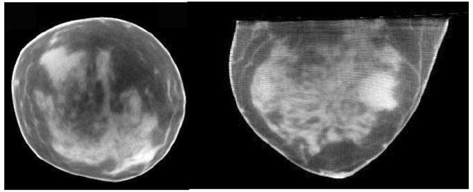
Reconstructed CT (left) coronal and (right) transverse image slices of human subject volunteer.
4. Conclusion
Imaging with a dedicated dual-modality breast imaging tomographic system may help to improve identification and localization of lesions during patient screening, diagnostic work-ups and therapeutic monitoring of response. The two main advantages of having a dedicated versus a whole-body imaging system are that the x-ray radiation dose is limited to only the breast and axillary regions. Thus, imaging can be optimized for the breast, and potentially ‘peer’ into the chest wall and axillary region to improve the detection of small breast tumors without unduly contorting the subjects. Furthermore, this system can acquire images sequentially with the SPECT and CT sub-systems without transferring the subject from one location to another or moving the patient bed in between acquisitions. This should minimize acquisition time and allow SPECT and CT images to be consistent and correlate with each other for easier co-registration. Our current prototype dedicated SPECT-CT system can provide volumetric fully 3D registered and fused breast images. This system can image an entire breast close to the chest wall to facilitate the detection and biopsy of small tumors without breast compression. This system has common emission (SPECT) and transmission (cone-beam CT) FOVs that intersect each other, as opposed to being either on separate systems or linearly juxtaposed on separate gantries.
Here, the CT component of the hybrid assembly was characterized for various system orientations and acquisition trajectories. Imaging results of the disk phantom with and without acrylic balls, and tiered cross-shaped ball phantoms suspended throughout the 3D breast volume acquired using stationary polar tilted simple circular orbits, demonstrated geometric distortions and reconstruction inaccuracies (i.e. overlapping structures, circular ring) that manifest themselves as cupping artifacts. These cupping artifacts are distinctly different from those commonly known to arise from scatter and beam hardening. Given that insufficient cone-beam sampling yields an additional component of reconstruction ‘cupping’, any general scatter correction algorithm applied to these regions may indeed ‘flatten’ the response across the image, but would incorrectly account for the measured scatter response. That resulting data could not explicitly be considered quantitative in terms of resulting attenuation coefficients. Blur around the disks in the disk phantom was progressively observed away from the horizontal plane of the cone-beam, which had the more complete sampling using simple circular orbits. From the results of this study, we suggest that these incomplete sampling-based cupping artifacts are an addition to but distinct from any scatter or beam hardening induced cupping artifacts, indicating that simple scatter correction algorithms present in some systems may thus overestimate the scatter correction. Additionally, the results also showed that high-frequency information (smaller object size) was more preserved in incompletely sampled data, implying that resolution recovery is also dependent on the frequency components of an object. One caveat to note about the object frequency dependence, however, is that there may still be incorrect information transferred from out-of-plane regions into any plane of interest due to incomplete sampling. Thus, interpreting absolute attenuation coefficients should be made cautiously unless the system has more complete polar sampling as well.
Currently in our prototype dual-modality dedicated mammotomography system, the CT component has a stationary tilt. Results indicate that having the cone-beam flat closer to the chest wall (i.e. negative CT system tilt) allows for more complete sampling near the chest wall, and more lesion-like small spherical objects can be clearly seen than for a completely sampled complex 3D trajectory. The drawback is that there are overlapping structures throughout the volume, geometric distortion and incomplete sampling in the rest of the reconstruction volume. Clinically, this can translate to decreased contrast and size estimation of a lesion in the breast, as well as inaccurate absolute attenuation coefficient determination. Regardless of these known inaccuracies due to insufficient sampling with circular cone-beam acquisitions, CT patient images have shown that distortion appears to be nominal with high resolution recovery. However, for more distortion-free images, use of complex 3D trajectories in imaging procedures having more complete and uniform sampling is suggested. Our ongoing goal is to develop a CT sub-system with a complex 3D trajectory capability as part of the hybrid system that would allow for more complete and uniform sampling of the entire image volume, and subsequently lead to more quantitative CT image content potentially useful in tissue characterization. A large number of complex 3D acquisition trajectories are possible with the completely flexible positioning CT system; many would facilitate better sampling and are under investigation and development (Crotty et al 2006). The volume limitation issue of complex sampling may be ameliorated by lowering the object farther into the FOV, provided it is possible to do so (Cutler et al 2007, Crotty et al 2008).
Acknowledgments
This work was supported by NIH R01-CA096821, and in part by DOD W81XWH-06-1-0791, W81XWH-08-1-0352 and DOD W81XWH-05-1-0280. MPT is the inventor of this breast CT and hybrid imaging technology, and is named as an inventor on the patent for this technology applied for by Duke. If this technology becomes commercially successful, MPT and Duke could benefit financially. MPT is a founder and consultant of Zumatek.
References
- Bartolac S, Noo F, Clackdoyle R, Moseley D, Siewerdsen J, Jaffray D. A local Fourier description of artifacts in circular cone beam computed tomography. Med Phys. 2006;33:2287. doi: 10.1118/1.3062875. [DOI] [PMC free article] [PubMed] [Google Scholar]
- Boone JM, Kwan AL, Yang K, Burkett GW, Lindfors KK, Nelson TR. Computed tomography for imaging the breast. J Mammary Gland Biol Neoplasia. 2006;11:103–11. doi: 10.1007/s10911-006-9017-1. [DOI] [PubMed] [Google Scholar]
- Bowsher JE, Tornai MP, Peter J, Gonzalez Trotter DE, Krol A, Gilland DR, Jaszczak RJ. Modeling the axial extension of a transmission line source within iterative reconstruction via multiple transmission sources. IEEE Trans Med Imaging. 2002;21:200–15. doi: 10.1109/42.996339. [DOI] [PubMed] [Google Scholar]
- Brzymialkiewicz CN, Tornai MP, McKinley RL, Bowsher JE. Evaluation of fully 3D emission mammotomography with a compact cadmium zinc telluride detector. IEEE Trans Med Imaging. 2005;24:868–77. doi: 10.1109/tmi.2005.852501. [DOI] [PMC free article] [PubMed] [Google Scholar]
- Brzymialkiewicz CN, Tornai MP, McKinley RL, Cutler SJ, Bowsher JE. Performance for dedicated emission mammotomography for various breast shapes and sizes. Phys Med Biol. 2006;51:5051–64. doi: 10.1088/0031-9155/51/19/021. [DOI] [PMC free article] [PubMed] [Google Scholar]
- Chen B, Ning R. Cone-beam volume CT mammographic imaging: feasibility study. Med Phys. 2002;29:755–70. doi: 10.1118/1.1461843. [DOI] [PubMed] [Google Scholar]
- Chen L, Shaw CC, Tu S, Altunbas MC, Wang T, Lai C, Liu X, Kappadath SC. Cone-beam CT breast imaging with a flat panel detector: a simulation study. Proc SPIE: Phys Med Imaging. 2005;5745:943–51. [Google Scholar]
- Crotty DJ, Brzymialkiewicz CN, McKinley RL, Tornai MP. Optimizing orientation of SPECT and CT detectors through quantification of cross contamination in a dual modality mammotomography system. Proc IEEE Med Imaging Conf. 2005;3:1672–6. [Google Scholar]
- Crotty DJ, Brzymialkiewicz CN, McKinley RL, Tornai MP. Investigation of emission contamination in the transmission image of a dual modality computed mammotomography system. Proc SPIE: Phys Med Imaging. 2006;6142:664–74. [Google Scholar]
- Crotty DJ, Cutler SJ, McKinley RL, Madhav P, Perez KL, Tornai MP. Improved chest wall imaging through combined circular trajectories in dedicated dual modality SPECT-CT breast molecular imaging. Proc IEEE MRBC Conf. 2008:5650–65. [Google Scholar]
- Crotty DJ, Madhav P, McKinley RL, Tornai MP. Investigating novel patient bed designs for use in a hybrid dual modality dedicated 3D breast imaging system. Proc SPIE: Phys Med Imaging. 2007a;6150:65101H. [Google Scholar]
- Crotty DJ, McKinley RL, Tornai MP. Experimental spectral measurements of heavy K-edge filtered beams for x-ray computed mammotomography. Phys Med Biol. 2007b;52:603–16. doi: 10.1088/0031-9155/52/3/005. [DOI] [PMC free article] [PubMed] [Google Scholar]
- Cutler SJ, Madhav P, Perez KL, Crotty DJ, Tornai MP. Comparison of reduced angle and fully 3D acquisition sequencing and trajectories for dual-modality mammotomography. Proc IEEE Med Imaging Conf. 2007;6:4044–50. [Google Scholar]
- Davis G. Explicit control of image noise and error properties in cone-beam microtomography using dual concentric circular source loci. Nucl Instrum Methods Phys Res A. 2005;547:679–85. [Google Scholar]
- Erdogan H, Fessler JA. Ordered subsets algorithms for transmission tomography. Phys Med Biol. 1999;44:2835–51. doi: 10.1088/0031-9155/44/11/311. [DOI] [PubMed] [Google Scholar]
- Hany TF, Steinert HC, Goenes GW, Buck A, von Schulthess GK. Improvement of diagnostic accuracy of PET imaging using an in-line PET-CT system—initial results. Radiology. 2002;225:575–81. doi: 10.1148/radiol.2252011568. [DOI] [PubMed] [Google Scholar]
- Hasegawa BH, Wong KH, Iwata K, Barber WC, Hwang AB, Sakdinawat AE, Ramaswamy M, Price DC, Hawkins RA. Dual-modality imaging of cancer with SPECT/CT. Technol Cancer Res Treat. 2002;1:449–58. doi: 10.1177/153303460200100605. [DOI] [PubMed] [Google Scholar]
- Hubbell JH, Seltzer SM. Tables of x-ray mass attenuation coefficients and mass energy-absorption coefficients 1 keV to 20 MeV for elements Z = 1 to 92 and 48 additional substances of dosimetric interest. Gaithersburg: National Institutes of Standards and Technology; 1996. [Google Scholar]
- Israel O, Keidar Z, Iosilevsky G, Bettman L, Sachs J, Frenkel A. The fusion of anatomic and physiologic imaging in the management of patients with cancer. Semin Nucl Med. 2001;31:191–205. doi: 10.1053/snuc.2001.23525. [DOI] [PubMed] [Google Scholar]
- Junhai W, Hongbing L, Wei Z, Zigang W, Zhengrong L. A study on truncated cone-beam sampling strategies for 3D mammography. Proc IEEE Med Imaging Conf. 2003;5:3200–4. [Google Scholar]
- Kudo H, Saito T. Feasible cone beam scanning methods for exact reconstruction in three-dimensional tomography. J Opt Soc Am A. 1990;7:2169–83. doi: 10.1364/josaa.7.002169. [DOI] [PubMed] [Google Scholar]
- Madhav P, Crotty DJ, McKinley RL, Tornai MP. Initial development of a dual-modality SPECT-CT system for dedicated mammotomography. Proc IEEE Med Imaging Conf. 2006;4:2382–6. [Google Scholar]
- Madhav P, Cutler S, Crotty D, Perez K, McKinley R, Marcom P, Wong T, Tornai M. Pilot patient studies using a dedicated dual-modality SPECT-CT system for breast imaging. Med Phys. 2008;35:2894. [Google Scholar]
- McKinley RL, Brzymialkiewicz CN, Madhav P, Tornai MP. Investigation of cone-beam acquisitions implemented using a novel dedicated mammotomography system with unique arbitrary orbit capability. Proc SPIE: Phys Med Imaging. 2005a;5745:609–17. [Google Scholar]
- McKinley RL, Tornai MP. Preliminary investigation of dose for a dedicated mammotomography system. Proc SPIE: Phys Med Imaging. 2006;6142:60–70. [Google Scholar]
- McKinley RL, Tornai MP, Samei E, Bradshaw ML. Simulation study of a quasi-monochromatic beam for x-ray computed mammotomography. Med Phys. 2004;31:800–13. doi: 10.1118/1.1668371. [DOI] [PubMed] [Google Scholar]
- McKinley RL, Tornai MP, Samei E, Bradshaw ML. Initial study of quasi-monochromatic beam performance for x-ray computed mammotomography. IEEE Trans Nucl Sci. 2005b;52:1243–50. [Google Scholar]
- Schillaci O, Simonetti G. Fusion imaging in nuclear medicine: applications of dual-modality systems in oncology. Cancer Biother Radiopharm. 2004;19:1–10. doi: 10.1089/108497804773391621. [DOI] [PubMed] [Google Scholar]
- Shreve PD. Adding structure to function. J Nucl Med. 2000;41:1380–2. [PubMed] [Google Scholar]
- Smith BD. Image reconstruction for cone beam projections: necessary and sufficient conditions and reconstruction methods. IEEE Trans Med Imaging. 1985;4:14–25. doi: 10.1109/TMI.1985.4307689. [DOI] [PubMed] [Google Scholar]
- Tornai MP, McKinley RL, Brzymialkiewicz CN, Madhav P, Cutler SJ, Crotty DJ, Bowsher JE, Samei E, Floyd CE. Design and development of a fully-3D dedicated x-ray computed mammotomography system. Proc SPIE: Phys Med Imaging. 2005;5745:189–97. [Google Scholar]
- Tuy HK. An inversion formula for cone-beam reconstruction. SIAM J Appl Math. 1983;43:546–52. [Google Scholar]
- Vedula AA, Glick SJ. Computer simulations of CT mammography using a flat panel imager. Proc SPIE: Phys Med Imaging. 2003;5030:349–60. [Google Scholar]
- Webb S, Sutcliffe J, Burkinshaw L, Horsman A. Tomographic reconstruction from experimentally obtained conebeam projections. IEEE Trans Med Imaging. 1987;6:67–73. doi: 10.1109/TMI.1987.4307799. [DOI] [PubMed] [Google Scholar]
- Zeng GL, Clack R, Gullberg GT. Implementation of Tuy’s cone-beam inversion formula. Phys Med Biol. 1994;39:493–507. doi: 10.1088/0031-9155/39/3/014. [DOI] [PubMed] [Google Scholar]