Abstract
We studied the dependence of single-molecule fluorescence on the size of nearby metal particles. The silver particles were synthesized with average diameters of metal cores being 5, 20, 50, 70, and 100 nm, respectively. A single-stranded oligonucleotide was chemically bound to a single silver particle and a Cy5-labeled complementary single-stranded oligonucleotide was hybridized with the particle-bound oligonucleotide. The space between the fluorophore and metal core was separated by a rigid hybridized DNA duplex of 8 nm length. The single fluorescence images and intensity traces were recorded by scanning confocal microscopy. The single fluorophore-labeled 50 nm silver particles displayed the most enhanced intensity, a factor of 17-fold increase relative to the free fluorophores in the absence of metal. Numerical simulations by the finite-difference time-domain (FDTD) method and results from Mie theory were used to compare with the experimental results. The 50 nm silver particles were also labeled by multiple fluorophores. The fluorescence intensity of multiple fluorophore-labeled metal particles increases dramatically with the loading number and reached 400-fold relative to the free single fluorophore when the loading number of fluorophore per metal particle was 50. The fluorophore also displayed better photostability when binding on the metal particle. These results can aid us to develop novel nanoscale fluorophores for clinical diagnostics and bioassay.
Introduction
Fluorescence is known to be enhanced by 1-3 orders of magnitude when a fluorophore is localized near a metal nanoparticle. This phenomenon is defined as metal-enhanced fluorescence (MEF).1-5 MEF is primarily due to a near-field interaction of fluorophores with metal particles.6-11 The fluorophores interact with the localized enhanced electric fields around the metal that is induced by the incident light. The enhanced field around the particle is also known as the plasmon resonance. Hence, MEF can be understood to occur due to the interaction of fluorophores with the plasmon resonance from metal particle. Both the excitation and emission of the fluorophore is influenced by the coupling interaction with the metal plasmon resonance. This approach can be used to develop novel nanoscale fluorophores: metal plasmon-coupled probes (PCPs). PCPs are expected to display increasing brightness and photostability compared to typical organic fluorophores.9a
To optimize the conditions of brighter and more photostable PCPs, it is critical to investigate what is the distribution of electric field near the metal particle and how the local field influences the fluorophore. During the past several years, some calculation techniques, such as the finite-difference time-domain (FDTD) method, have been developed to study the electric field near the metal particle,2b but there is no literature to cite the influence of the electric field to the fluorophore within the field. According to our recent model developed from Mie theory, the photophysical properties of PCPs rely on the core size of the metal particle.8,9 Hence, it is of importance to experimentally determine the dependence of the emission behavior of fluorophores on the size of the metal particles and theoretically interpret the experimental results. Herein, we reported the synthesis of silver particles with different sizes, chemical binding of the fluorophore on the metal particle, and monitoring the single-molecule fluorescence image. The silver particles were coated by N-(2-mercaptopropionyl)glycine (abbreviated as tiopronin) and displayed good chemical stability and water solubility.12 The sizes of the metal particles ranged between 5-100 nm and were controlled by the preparing conditions.13
Single-molecule detection is a valuable method to study the emission properties of a fluorophore because of its ability to bypass ensemble averaging and allow resolution of actual distributions of the spectral parameters.14 Such details of the underlying distribution become crucially important when the system under study is heterogeneous.15 In this paper, we bound a single fluorophore on each silver particle to study the dependence of single-molecule fluorescence on the metal core size. To control the loading number of fluorophores, the metal particles were quantitatively succinimidylated with (2-mercaptopropionylamino)acetic acid 2,5-dioxopyrrolidin-1-yl ester via ligand exchange.16 The aminated single-stranded oligonucleotides were covalently bound to the silver particles via condensation between the terminal succinimidyl ester moiety on the silver particle and the amino moiety on the oligonucleotide in the molar ratio of oligonucleotide/metal particle = 1/1 (Scheme 1).17 The metal particles were fluorescently labeled by hybridization with fluorophore-labeled complementary single-stranded oligonucleotides.17,18 To reduce the influence from the metal plasmon absorptions at the excitation and emission wavelengths,19 a near-infrared fluorophore cyanine 5 (Cy5) was employed to label the complementary single-stranded oligonucleotide in this case. The bound fluorophores on the metal particles were spatially separated from the metal cores by the hybridized DNA duplex chains, which were about 8 nm in length, to reduce the competitive quenching.6c Scanning confocal microscopy was used to record the single-molecule fluorescence images of the bound fluorophores on the metal particles.
SCHEME 1. Succinimidylated Silver Particle Covalently Bound with Aminated Single-Stranded Oligonucleotide and Fluorescently Labeled by Complementary Single-Stranded Cy5-Labeled Oligonucleotidea.

aOligonucleotide sequences used in the experiments are given.
We are also interested in developing bright and photostable PCPs as novel probes.20 Therefore, besides the single fluorophore-labeled metal particles, we also bound more than one fluorophore on each metal particle to study the dependence of emission properties on the loading number of fluorophores per metal particle. In addition, the near-field interaction was discussed on the basis of lifetime data in this paper.
Experimental Section and Theoretical Calculation
All reagents and spectroscopic grade solvents were used as received from Fisher or Aldrich. RC dialysis membrane (MWCO 50 000) was obtained from Spectrum Laboratories, Inc. Nanopure water (>18.0 MΩ·cm), purified using a Millipore Milli-Q gradient system, was used in all experiments. (2-Mercaptopropionylamino)acetic acid 2,5-dioxopyrrolidin-1-yl ester was synthesized as previous reported.16 Oligonucleotides (Scheme 1) were synthesized by the Biopolymer Laboratory at the University of Maryland at Baltimore, in which aminated oligonucleotide was also synthesized with one amino group substituted on the pyrimidine ring of a thymine base and the complementary oligonucleotide was labeled by Cy5.
Preparing Succinimidylated Tiopronin-Coated Metal Nanoparticles
Tiopronin-coated silver nanoparticles were prepared by chemical reduction of silver nitrate using ascorbic acid.21 A 10 mg amount of silver nitrate and 30 mg of trisodium citrate were co-dissolved in 50 mL of water. A 10, 20, 100, 500, or 1000 μL aliquot of 0.1 N NaOH solution (Table 1) was added dropwise under stirring for 2 min, respectively. A 20 mg amount of ascorbic acid in 10 mL of water was then added dropwise for 5 min, and the solution was stirred for an additional 1 h. A 50 mg amount of tiopronin in 5 mL of water was added at pH) 7.0, and the solution was stirred for 1 h. The solution was centrifuged at 8000 rpm to remove the suspension. After being washed with water, the residue solids were redispersed in 50 mL of water.
TABLE 1. Summary of Preparation Condition and Fluorescence Enhancement Data for the Single Fluorophore-Labeled Silver Particles with Different Metal Core Sizes.
| sample 1 | sample 2 | sample 3 | sample 4 | sample 5 | sample 6 | |
|---|---|---|---|---|---|---|
| amount of NaOH (μL) | 10 | 20 | 100 | 500 | 1000 | |
| particle size (nm) | 100 | 70 | 50 | 20 | 5 | |
| enhancement efficiency | 5.8 | 15 | 17 | 8.2 | 1.5 | |
| lifetime (ns) | 2.4 | 0.97 | 0.38 | 0.40 | 0.32 | 1.3 |
These tiopronin-coated silver particles were succinimidylated by ligand exchange (Scheme 1). (2-Mercaptopropionylamino)-acetic acid 2,5-dioxopyrrolidin-1-yl ester and tiopronin-coated silver particles were co-dissolved in water at a molar ratio of 1/2 and stirred for 24 h.17 Unbound organic components were left in solution by centrifugation at 8000 rpm. The residual was washed with water and then dispersed in 50 mL of water.
Binding and Hybridizing Oligonucleotides on Metal Nanoparticles
Aminated oligonucleotides were chemically bound onto the succinimidylated silver particles by condensation between the amino moieties on the oligonucleotides and the terminal succinimidyl ester moieties on the silver particles.17 The oligonucleotides and succinimidylated metal particles were co-dissolved in water at a molar ratio of 1/1 with continuous stirring for 24 h. The metal particles were centrifuged at 8000 rpm to remove the unbound oligonucleotides in suspension. The residue was washed with water and dispersed in 50 mM phosphate-buffered saline (PBS) buffer solution at pH = 7.2.
The fluorophore-labeled complementary oligonucleotides were bound to the metal particles by hybridization with the bound oligonucleotides,16,17 which was performed at a molar ratio of particle/labeled oligonucleotide) 1/1 for 24 h. The suspension was removed by centrifugation at 8000 rpm. The residual particles were washed with the buffer and then dialyzed against the buffer solution (MWCO 50 000) to remove any unbound impurities for the spectral measurements.
Spectra, Images, and TEM Measurements
Absorption spectra were monitored with a Hewlett-Packard 8453 spectrophotometer. Ensemble fluorescence spectra were recorded in solution with a Cary Eclipse fluorescence spectrophotometer. Ensemble lifetimes were measured by PicoQuant modular fluorescence lifetime spectrometer (Fluo Time 100) using PicoQuant 635-690 nm light emitting diode (LED; LDH 8-1-568) as the light source with a resolution of 34 ps. A 650 nm filter was used to isolate the donor emission. Data were analyzed using a single- or double-exponential model. For single-molecule measurements, a dilute solution was dispersed on a precleaned glass coverslip. The coverslips (18 × 18 μm, Corning) used in the experiments were first soaked in a 10/1 (v/v) mixture ofconcentrated H2SO4 and 30% H2O2 overnight, extensively rinsed with water, sonicated in absolute ethanol for 2 min, and dried with an air stream. The sample solution was adjusted to a nanomolar concentration to give an appropriate surface density for single-molecule studies. All single-molecule measurements were performed using a time-resolved confocal microscopy (MicroTime 200, PicoQuant). Briefly, it consists of an inverted microscope coupled to a high-sensitivity detection setup. A single-mode pulsed-laser diode (635 nm, 100 ps, 40 MHz; PDL800, PicoQuant) was used as the excitation source. An oil immersion objective (Olympus, 100×, 1.3NA) was employed both for focusing laser light onto the sample and collecting fluorescence emission from the sample. The fluorescence that passed a dichroic mirror (Q655LP, Chroma) was focused onto a 75 μm pinhole for spatial filtering to reject out-of-focus signals. The integration time was 0.6 ms/pixel. The data were stored in the time-tagged-time-resolved (TTTR) mode, which allows recording every detected photon with its individual timing information with regard to both the location or the sample and the time delay between excitation and emission. In combination with a pulsed diode laser, instrument response function (IRF) widths of about 300 ps full width at half-maximum (fwhm) can be obtained, which permits the recording of sub-nanosecond fluorescence lifetimes, extendable to less than 100 ps with reconvolution. Lifetimes were estimated by fitting to a χ2 value of less than 1.2 and with a residuals trace that was fully symmetrical about the zero axis.
Transmission electron micrographs (TEMs) were taken with a side-entry Philips electron microscope at 120 keV. Samples were cast from water solutions onto standard carbon-coated (200-300 Å) Formvar films on copper grids (200 mesh) by placing a droplet of a 1 mg/mL aqueous sample solution on grids. The size distribution of the metal core was analyzed with Scion Image Beta Release 2 counting at least 200 particles.
FDTD Calculations
The finite-difference time-domain technique is an implementation of Maxwells’s time-dependent curl equations for solving the temporal variation of electromagnetic waves within a finite space that contains a target of arbitrary shape and has recently become the state-of-the-art method for solving Maxwell’s equations for complex geometries.22-34 Since FDTD is a direct time and space solution, it offers the user a unique insight into all types of problems in electromagnetics and photonics. Furthermore, FDTD can also be used to obtain the frequency solution by exploiting Fourier transforms; thus, a full range of useful quantities in addition to fields around particles can be calculated, such as the complex Poynting vector and the transmission/reflection of light. In the FDTD technique, Maxwell’s curl equations are discretized by using finite-difference approximations in both time and space that are easy to program and are accurate.22-34 To achieve high accuracy for realizing the spatial derivatives involved, the algorithm positions the components of the electric and magnetic field about a unit cell of the lattice that constitutes the FDTD computational domain. Each individual cube in the grid is called the Yee cell as it was first designed elegantly by Yee.23
Our FDTD calculations were performed using the program FDTD Solutions (Version 5.0) provided by Lumerical Solutions, Inc., (Vancouver, Canada). The calculations were performed with the parallel FDTD option on a Dell Precision PWS690 Workstation with the following components: Dual Quad-Core Intel Xeon E5320 processors at 1.86 GHz, and 8 GB RAM. All postprocessing of FDTD data were performed using MATLAB (version 7.0) provided by Mathworks (Natick, MA). To maintain the accuracy and stability of the FDTD calculations, the smallest grid size to accurately model the prescribed system without being computationally prohibitive was obtained in an iterative fashion (convergence testing). In our implementation of FDTD, convergence testing was done by starting the first calculation with a grid size of λ0/20, where λ0 is the smallest wavelength expected in the simulation, and then reducing the grid size by half in sequential simulations and comparing the results of the calculations. The reduction of the grid size was stopped when we approached a grid size (Δ) where results closely match with the set of results that are obtained from half that particular grid size (Δ/2).34 The numerical implementation of Maxwell’s equations in the FDTD algorithm requires that the time increment Δt have a specific bound relative to the spatial discretization Δ (as mentioned above) to ensure the stability of the time-stepping algorithm.34 In our implementation of FDTD, the time step of the simulation is determined by the values of the spatial grid to ensure numerical stability and the user has the flexibility to set the total time of the simulation in femtoseconds (fs).34b Typically our simulations ranged around 300 fs. This led to all of our simulations having an excess of 50 000 time steps. Our FDTD software has frequency domain monitors that perform discrete Fourier transforms of the time domain fields while the simulation is running. In this manner, continuous wave (CW) information is obtained at any prespecified wavelengths for the various field components (Ex, Ey, Ez, Hx, Hy, and Hz). Additionally, the time-domain monitors can provide time-domain information for the various field components within the FDTD simulation region over the entire course of the simulation. At the end of the simulation, the various field components are checked to see if they decay to zero, thus indicating that the simulation has run for a sufficiently long time for the CW information obtained by Fourier transformations to be valid.34b
Results and Discussion
Silver particles were synthesized by reduction of silver salt using ascorbic acid as the reduction agent.21 The silver particles were stabilized by the coated citrate molecules. The citrate molecules were further replaced by the tiopronin, and the tiopronin-coated silver particles were observed to display good solubility and chemical stability in water. It is important for the following surface reactions occurring on the metal particles. The sizes of silver particles were controlled by the quantity of base in the reaction solution as described in Experimental Section and Theoretical Calculation (Table 1). These particles displayed a switching of color from yellow to blue in water, corresponding to an increase of the size.14 The absorbance spectral measurements showed typical plasmon absorbances at 397, 411, 454, 522, and 598 nm, respectively, accompanied by simultaneous band broadenings (Figure 1), with decreasing base amounts in solution. Representative TEM images showed average diameters of the metal cores to be 5, 20, 50, 70, and 100 nm (Figure 2). The size distributions of metal particles were analyzed with Scion Image Beta Release 2 counting at least 200 TEM images. It was shown from the histograms that the small particles (e.g., 5 and 20 nm) appeared to be approximately homogeneous but the large particles (e.g., 100 nm) appeared to be heterogeneous. However, at least 80% of these particles were observed to be distributed in ranges of 5 ± 4, 20 ± 10, 50 ± 20, 70 ± 20, and 100 ± 40 nm, respectively, indicating that the differences were significant enough (although there was some overlap in size distributions). Thus, we are confidant that the size-dependence results discussed in this paper using the current metal particles are reliable. The chemical compositions can be approximately estimated on the basis of their average size. Accordingly, their average chemical compositions were ca. (Ag) 4 × 10³-(Tio) 3 × 10², (Ag) 2 × 10⁵-(Tio) 5 × 10³, (Ag) 4 × 10⁶-(Tio) 3 × 10⁴, (Ag) 1 × 10⁷-(Tio) 6 × 10⁴, and (Ag) 3 × 10⁷-(Tio) \ × 105, respectively.
Figure 1.
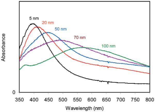
Absorbance spectra of tiopronin-coated silver particles with the different metal core sizes.
Figure 2.
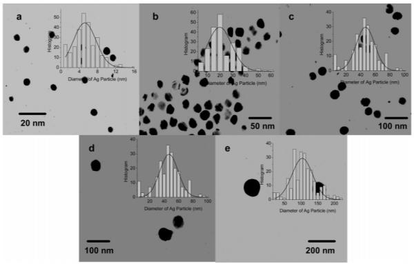
Transmission electron micrograph (TEM) images of silver particles with the different metal core sizes of (a) 5, (b) 20, (c) 50, (d) 70, and (e) 100 nm. Histograms of the size distributions of the metal particles were inserted correspondingly.
The TEM images revealed that most metal particles were spherical shape. According to experimental results from Chumanov, the silver particles can display a significant quadrupole resonance only when their diameters are larger than 80 nm.35 In this case, we found that only 100 nm silver particles displayed a clear quadrupole resonance but others did not (Figure 1), which was in accordance with the previous report.
We first examined the emission properties of single fluorophore-labeled metal particles. The metal particles were succinimidylated by (2-mercaptopropionylamino)acetic acid 2,5-dioxopyrrolidin-1-yl ester via ligand exchange. The ligand exchange reaction is known to occur at 1/1 molar ratio on the metal particle.36 To guarantee that only a single succinimidyl ester molecule was displaced on each metal particle, the succinimidyl ester and metal particle was co-dissolved in water at a molar ratio of 1/2.17 As a result, the average number of succinimidyl esters was supposed to be less than 0.5 on each metal particle, even if all succinimidyl molecules were exchanged on the metal particles. In other words, it was supposed that only half of the metal particles were functionalized by a single succinimidyl ligand in this case.
The animated single-stranded oligonucleotide was covalently bound to the succinimidylated metal particle via condensation. With only one succinimidyl ligand on each metal particle, it was expected to covalently bind by a single oligonucleotide molecule in this surface reaction. Thus, a single Cy5-labeled complementary oligonucleotide was hybridized with the bound oligonucleotide on the metal particle in 50 mM PBS buffer solution at pH) 7.2.17,18 The actual loading number of fluorophores per metal particle could be estimated quantitatively when dissolving the metal core with NaCN aqueous solution.37 The released fluorophore-labeled oligonucleotide was observed to display an identical emission spectrum to the free oligonucleotide in the absence of metal, and the concentration of the released fluorophore was estimated from the emission intensity. The value was 0.3, indicating that more than half of the metal particles were not labeled, indeed as we expected. Furthermore, we inferred that the labeled silver particles should contain only one fluorophore. It was noted that the scattering signal from the unlabeled particle was less than 5% of the fluorescence signals, so we did not further separate the unlabeled silver particles from the labeled particles. The above surface reactions on the silver particles did not significantly alter their absorbance spectra and TEM images, because only few reactive ligands were involved.
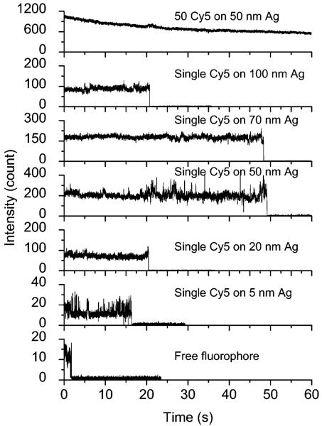
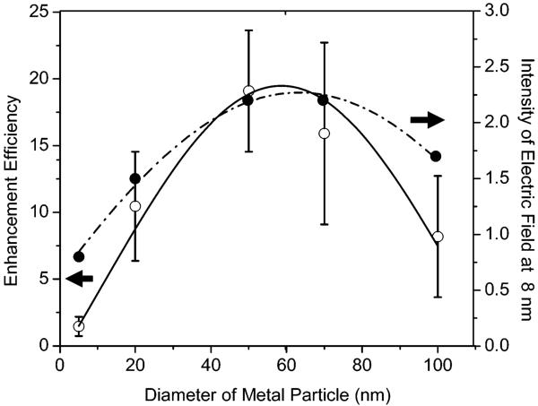
Free Cy5-labeled oligonucleotide displayed an emission maximum at 661 nm upon excitation at 620 nm in buffer solution (Figure 3).17 The emission wavelength of bound fluorophores on the metal particles was slightly shifted to 662 nm with a simultaneous band broadening, which was probably due to a restriction of movement for the bound fluorophore.38 The hybridized DNA duplex chains can be regarded as the rigid rods that separate the fluorophores from the surfaces of metal cores. Since the DNA used in the current experiment contains 23 base pairs, the separation between the fluorophore and metal core is about 8 nm. This distance is close to the optimized value for the most efficient metal-enhanced fluorescence.9,11b Typical fluorescence images of a 5 × 5 μm region were recorded using confocal microscopy (Figure 4). It was shown that the fluorescence images for time-dependent analysis provided initial and quantitative information on the brightness at the single-molecule level. It was shown that the spots in the presence of large metal particles were much brighter than those by the samples in the absence of metal or in the presence of small metal particles. Histograms of the intensity were constructed using at least 50 molecules (Figure 5), in which only the spots displaying single-step photobleaching were included in the analysis. The results revealed that the center intensity values were significantly shifted to high levels with increasing size of the metal particle. The time traces were collected using the same excitation. The time profiles illustrated the overall trends of fluorophores under the excitation (Figure 6). Most of the time traces showed clear one-step photobleaching, corresponding to typical behavior from a single fluorophore. The intensity was observed to be fairly constant until dropping abruptly to the background level in a single step. The enhancement efficiency was estimated by a ratio of the average intensity of a single fluorophore on the metal particles over the intensity of free Cy5-labeled oligonucleotide in the absence of metal and was plotted against the size of the metal particle (Figure 7), showing an initial increase with the metal particle size and then decrease. The steady state of maximal enhancement occurred on the intermediate size of the 50 nm silver particle, and the value was 17-fold.
Figure 3.
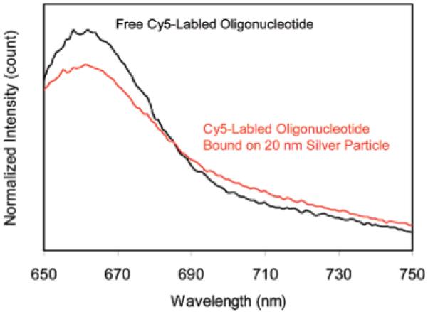
Ensemble emission spectra of Cy5-labeled oligonucleotide in the absence of metal and bound on the 20 nm silver particles.
Figure 4.
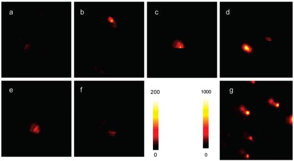
Respective fluorescence images of single-labeled (a) free Cy5; a single fluorophore on (b) 5, (c) 20, (d) 50, (e) 70, and (f) 100 nm silver particle; and (g) 50 fluorophores on 50 nm silver particle. The intensity bar for a-f is 0-200 and that for g is 0-1000. Sample g was excited at 20% laser intensity of the other samples. The 5 × 5 μm images are 100 × 100 pixels within integration time of 0.6 ms/pixel.
Figure 5.
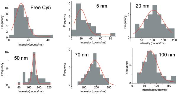
Histograms of emission intensity from single Cy5 fluorophores loaded on different-size silver particles.
Figure 6.
Respective time traces of free Cy5-labeled oligonucleotide, single Cy5 on the metal particles with the different metal core sizes of 5, 20, 50, 70, and 100 nm, and 50 fluorophores loaded on a single 50 nm silver particle.
Figure 7.
Dependence of enhancement efficiency of single-fluorophore-labeled metal particle and the electric field intensity at 8 nm away from the metal core on the size of the metal core.
We now consider the origin of the increased fluorescence from the fluorophores attached to the metal particles. It is known that metal-enhanced fluorescence occurs via near-field interactions of the fluorophore with the metal substrate, which can be described as localizing a fluorophore in the electric field near a metal particle. Hence, the electric field distribution near the silver particles is an important element for understanding our results. Herein we calculate the distributions of electric fields near the different-size silver particles under incident light at 635 nm by the FDTD technique. The results reveal that the distribution of the electric field is dependent on the size of the silver particle (Figure 8). A circle is marked on each of the panels in Figure 8 to depict approximately a distance of 8 nm from the metal surface. This is because the hybridized DNA duplexes are about 8 nm long, so it is expected that the fluorophores are localized at 8 nm from the metal particles. It can be seen that the smallest silver particle (5 nm) does not have the near fields extend out to a distance of 8 nm, so the fluorescence from the fluorophore is not expected to be enhanced. With increasing the size of metal particle, the near fields are seen to extend further out from the metal. Thus, we can assume that the fluorophores are influenced by the intensity of near fields 8 nm from the metal surface. The intensities at this distance are estimated to be 0.8, 1.5, 2.2, 2.2, and 1.7, respectively (obtained from the color map), for the different samples in Figure 8 and plotted against the metal particle size (Figure 7). This curve displays a trend comparable to the enhancement efficiency on the same figure; i.e., the variation of the calculated field strength (8 nm from the surface of the metal particle) with particle size qualitatively correlates with the variation of the fluorescence enhancement factor with particle size. This implies that the FDTD calculation of field strength variation is consistent with the experimental observation of fluorescence enhancement. We are aware that MEF is a complicated process, where the metal particle affects both the excitation of the fluorophore and the intrinsic decay rate of fluorophore emission.9,40 In our FDTD calculations, we considered only the effect of the increased localized near fields around the metal particle due to the incident light field and did not consider the interaction of the excited fluorophore with the silver particle. Thus, we do not claim that this treatment is complete and definitive. However, we feel that the correlation between the strength of the localized near fields around the metal particles with the fluorescence enhancement factor does offer us a glimpse into the nature of metal-fluorophore interactions; i.e., increased near fields around metal particles can lead to increased fluorescence emission from fluorophores located within the extent of the localized fields.
Figure 8.
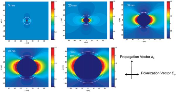
Intensity distribution of the electric field near the silver particles with different core sizes of 5, 20, 50, 70, and 100 nm. The field images were achieved by FDTD calculations. The circles represent the distance of 8 nm away from the metal cores.
As described above, the emission enhancement occurs through an increase of the intrinsic decay rate for the fluorophore near the metal surface,8,9 which is known to be reflected by a change of the fluorophore lifetime. In our analysis, the decay curve of the fluorophore on the metal particle was analyzed in terms of a double-exponential model. It is shown that all collected lifetimes of fluorophores on the metal are shortened significantly relative to that of the free Cy5 in the absence of metal. However, we still can compute the change in lifetime with the metal particle size. It was shown that the lifetime on the smallest silver particle (5 nm), and on the largest silver particle (100 nm), is distinctly longer than that on the intermediate size of metal particle such as 20, 50, or 70 nm (Table 1). This result supports our theoretical calculations and experimental results that the fluorophore can be influenced more efficiently with the intermediate size metal particles.
We also discuss the dependence of fluorescence enhancement on the size of the metal particle by Mie theory.9b The extinction properties of metal particles with the sub-wavelength sizes can be expressed by a combination of both absorption (CA) and scattering (CS) factors,
| (1) |
where k1 = 2πn1/λ0 is the wavevector of the incident light in medium 1 and α is the polarizability of the sphere of radius r,
| (2) |
and ∊m is the complex dielectric constant of metal. The first term represents the cross-section due to absorption, and the second term represents the cross-section due to scattering. According to our recent approach, we expect CA to cause quenching and CS to cause enhancement. The quenching term increases as the r3 factor, and the enhancement term increases as the r6 factor. Hence, a small particle can quench fluorescence because the absorption dominates over the scattering. Conversely, a large particle can enhance fluorescence because the scattering component is the dominant factor. This result is partially in accordance with our FDTD calculations but cannot be used to explain why the enhancement efficiency decreases significantly after the intermediate size of the metal particle.
So far, the work focused on the single-fluorophore-labeled metal particle. However, the multiple fluorophore on the silver particle is expected to increase brightness. On the basis of the results of single-fluorophore-labeled silver particles, we studied the emission behavior of multiple-fluorophore-labeled silver particles. The intermediate-size silver particle of 50 nm, which was known to display the most efficient enhancement in the single-fluorophore-labeling case, was used in multiple-fluorophore labeling. In the experiment, the silver particles were multiple-succinimidylated via ligand exchange. The reaction was done as described in the single-succinimidylate treatment case, but the molar ratio of the metal particle/succinimidyl compound was increased to 1/2000. Aminated oligonucleotides were covalently bound to the multiple-succinimidylated silver particles in various molar ratios from 5 to 2000 over the metal particles. An excess amount of Cy5-labeled oligonucleotide was used to hybridize with the multiple bound oligonucleotides on the metal particle. The loading number of fluorophores on the metal particle was quantified using NaCN to dissolve the metal cores. The emission spectra from the released Cy5-labeled oligonucleotides were recorded, and the emission intensities were used to estimate the concentration of fluorophore in solution to further calculate the loading number of fluorophores on the metal particle, which were 5, 10, 20, 30, and 50, respectively. This result showed a proportional increase with the amount of aminated oligonucleotide in the reaction mixture. We failed to load more fluorophores on the same silver particle, probably due to the repulsion of the negative-charged surfaces of metal particles at pH = 7.2 to the same negative-charged oligonucleotides.
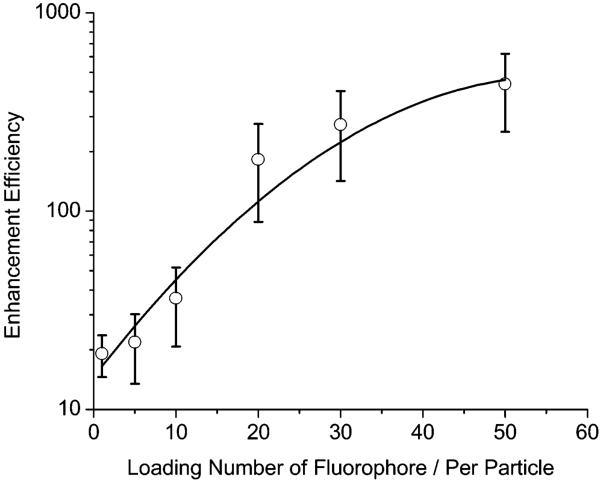
Although the multiple-fluorophore-labeled samples were excited at a much low laser intensity, the image brightness was still much higher relative to the single-fluorophore-labeled sample (Figure 4), indicating the overlapping effect of fluorophores on the multiple fluorophore-labeled sample. The time traces displayed a continuous intensity decay curve instead of a single-step photobleaching, verifying the presence of multiple fluorophores on one metal particle (Figure 6). The average brightness for the multiple fluorophore-labeled sample was collected from counting 50 images. The enhancement efficiency was estimated against the single free fluorophore in the absence of metal and plotted against the loading number per silver particle (Figure 9), showing a dramatic increase with an increasing number of fluorophores. No saturation is observed even though the loading number reaches the maximum of 50 in this system, indicating that more loading can result in an additional increase. The 50 fluorophore-labeled silver particles are 400-fold brighter than the free fluorophores in the absence of metal.
Figure 9.
Dependence of enhancement efficiency on the loading number per metal particle for the multiple-fluorophore-labeled silver particle with 50 nm diameter.
The multiple-fluorophore-labeled samples are supposed to have the same near-field interactions as the single-fluorophore-labeled samples. Their lifetimes are analyzed to be 0.8 ns, almost independent of the loading number. This value is longer than that by the single fluorophore on the same-size metal particle, probably due to the overlapping effect of multiple emissions on the same image spot. On the 50 nm metal particle, a single fluorophore on the single-fluorophore-labeled sample is known to cause a 17-fold increase in fluorescence by the fluorophore-metal interaction. If each fluorophore on the 50-fluorophore-labeled sample can separately lead to this interaction at the same scale, the overlapping effect of the multiple fluorophores can cause 24-fold increase of fluorescence on the same metal particle.
A shorter lifetime of fluorophore near a metal particle can result in less time for photochemistry while in the excited state, and thus more excitation-emission cycles prior to photobleaching.9a Hence, the labeled metal particles are expected to display better photostability than the free fluorophore in the absence of metal.41 This prediction has been well verified by the experimental data. The time traces by the single-labeled metal particle showed a significant extension of emissive time with the particle size (Figure 6). Under the same conditions, free Cy5 in the absence of metal is bleached completely in 2 s but the single-labeled 50 and 70 nm silver particles are bleached in almost 50 s, 25-fold longer. This observed time is further lengthened when the metal particles are labeled by multiple fluorophores. Only half of the fluorophores are photobleached in 60 s for the multilabeled silver particles, indicating that the multilabeled PCPs indeed display better photostability than the free fluorophores. Excellent brightness and photostability ensure the optimized PCPs being able to improve the sensitivity in clinical detection.
We also noticed from the time traces that the fluorescence blinking was obviously reduced after binding the fluorophores on the metal particles (Figure 6). This phenomenon was also observed in our previous report, in which the photoblinking of CdTe quantum dots was almost eliminated on the silver island surfaces.42 Hence, besides an increase of fluorescence intensity and increasing photostability, the loading of fluorophore on the metal particle can also provide us constant fluorescence signals without strong photoblinking.
Summary
In this paper, we studied the photophysical properties of single-fluorophore-labeled silver particles with different metal core sizes and the multiple-fluorophore-labeled metal particles. The silver particles were synthesized under controlled conditions with core sizes of 5, 20, 50, 70, and 100 nm, respectively. These metal particles were succinimidylated via ligand exchange, bound by aminated oligonucleotide, and then hybridized by Cy5-labeled complementary single-stranded oligonucleotide. The metal particles were first controlled for labeling by a single fluorophore per particle. Single-molecule fluorescence images were recorded using scanning confocal microscopy. The image analysis of single-fluorophore-labeled metal particles showed obvious metal-enhanced fluorescence relative to the free fluorophore in the absence of metal. The enhancement efficiency was noted to increase significantly with the size of the metal particle to initially exhibit a maximum at 50 nm and then decrease. The single-fluorophore-labeled 50 nm silver particles displayed the highest enhancement efficiency of 17-fold. Their time traces also express the increase in photostability with the particle size that is consistent with the trend of enhancement efficiency. FDTD calculations and a model developed from Mietheory were used to understand the experimental results. The metal particles were also labeled by multiple fluorophores, and these multiple fluorophore-labeled metal particles were observed to be brighter than the single-fluorophore-labeled metal particles, which was due to both effects of metal enhancement and emission overlapping. The 50-fluorophores-labeled 50 nm metal particles were 400-fold brighter than the single free fluorophores in the absence of metal. Lifetime measurements support the near-field interaction mechanism between the fluorophore and metal particle.
Acknowledgment
This research was supported by a grant from NIH, HG-02655, NCRR, and RR-08119.
References and Notes
- (1).Gryczynski I, Malicka J, Shen YB, Gryczynski Z, Lakowicz JR. J. Phys. Chem. B. 2002;106:2191. doi: 10.1021/jp013013n. [DOI] [PMC free article] [PubMed] [Google Scholar]; (b) Aslan K, Huang J, Wilson GM, Geddes CD. J. Am. Chem. Soc. 2006;128:4206. doi: 10.1021/ja0601179. [DOI] [PubMed] [Google Scholar]
- (2).(a) Sokolov K, Chumanov G, Cotton TM. Anal. Chem. 1998;70:3898. doi: 10.1021/ac9712310. [DOI] [PubMed] [Google Scholar]; (b) Shen Y, Swiatkiewicz J, Lin T-C, Markowicz P, Prasad PN. J. Phys. Chem. B. 2002;106:4040. [Google Scholar]; (c) Lee I-YS, Suzuki H, Ito K, Yasuda Y. J. Phys. Chem. B. 2004;108:19368. [Google Scholar]; (d) Yonzon CR, Jeoung E, Zou S, Schatz GC, Mrksich M, Van, Duyne RP. J. Am. Chem. Soc. 2004;126:12669. doi: 10.1021/ja047118q. [DOI] [PubMed] [Google Scholar]
- (3).(a) Song J-H, Atay T, Shi S, Urabe H, Nurmikko AV. Nano Lett. 2005;5:1557. doi: 10.1021/nl050813r. [DOI] [PubMed] [Google Scholar]; (b) Kawasaki M, Mine S. J. Phys. Chem. B. 2005;109:17254. doi: 10.1021/jp053167t. [DOI] [PubMed] [Google Scholar]
- (4).(a) Yu F, Persson B, Lofas S, Knoll W. J. Am. Chem. Soc. 2004;126:8902. doi: 10.1021/ja048583q. [DOI] [PubMed] [Google Scholar]; (b) Ekgasit S, Thammacharoen C, Yu F, Knoll W. Anal. Chem. 2004;76:2210. doi: 10.1021/ac035326f. [DOI] [PubMed] [Google Scholar]; (c) Baluschev S, Yu F, Miteva T, Ahl S, Yasuda A, Nelles G, Knoll W, Wegner G. Nano Lett. 2005;5:2482. doi: 10.1021/nl0517969. [DOI] [PubMed] [Google Scholar]
- (5).(a) Futamata M, Maruyama Y, Ishikawa M. J. Phys. Chem. B. 2003;107:7607. [Google Scholar]; (b) Sherry LJ, Chang S-H, Schatz GC, Van, Duyne RP, Wiley BJ, Xia Y. Nano Lett. 2005;5:2034. doi: 10.1021/nl0515753. [DOI] [PubMed] [Google Scholar]; (c) Oubre C, Nordlander P. J. Phys. Chem. B. 2005;109:10042. doi: 10.1021/jp044382x. [DOI] [PubMed] [Google Scholar]; (d) Wang H, Goodrich GP, Tam F, Oubre C, Nordlander P, Halas NJ. J. Phys. Chem. B. 2005;109:11083. doi: 10.1021/jp051466c. [DOI] [PubMed] [Google Scholar]
- (6).(a) Kummerlen J, Leitner A, Brunner H, Aussenegg FR, Wokaun A. Mol. Phys. 1993;80:1031. [Google Scholar]; (b) Antunes PA, Constantino CJL, Aroca RF, Duff J. Langmuir. 2001;17:2958. [Google Scholar]; (c) Kamat PV. J. Phys. Chem. B. 2002;106:7729. [Google Scholar]
- (7).(a) Kumbhar AS, Kinnan MK, Chumanov G. J. Am. Chem. Soc. 2005;127:12444. doi: 10.1021/ja053242d. [DOI] [PubMed] [Google Scholar]; (b) Bruzzone S, Malvaldi M, Arrighini GP, Guidotti C. J. Phys. Chem. B. 2005;109:3807. doi: 10.1021/jp045451a. [DOI] [PubMed] [Google Scholar]; (c) Hubert C, Rumyantseva A, Lerondel G, Grand J, Kostcheev S, Billot L, Vial A, Bachelot R, Royer P, Chang S.-h., Gray SK, Wiederrecht GP, Schatz GC. Nano Lett. 2005;5:615. doi: 10.1021/nl047956i. [DOI] [PubMed] [Google Scholar]; (d) Millstone JE, Park S, Shuford KL, Qin L, Schatz GC, Mirkin CA. J. Am. Chem. Soc. 2005;127:5312. doi: 10.1021/ja043245a. [DOI] [PubMed] [Google Scholar]
- (8).Lakowicz JR. Principles of Fluorescence Spectroscopy. 3rd ed. Springer; New York: 2006. [Google Scholar]
- (9).(a) Lakowicz JR. Anal. Biochem. 2001;298:1. doi: 10.1006/abio.2001.5377. [DOI] [PMC free article] [PubMed] [Google Scholar]; (b) Lakowicz JR. Anal. Biochem. 2005;337:171. doi: 10.1016/j.ab.2004.11.026. [DOI] [PMC free article] [PubMed] [Google Scholar]
- (10).(a) Kelly KL, Coronado E, Zhao LL, Schatz GC. J. Phys. Chem. B. 2003;107:668. [Google Scholar]; (b) Hao E, Li S, Bailey RC, Zou S, Schatz GC, Hupp JT. J. Phys. Chem. B. 2004;108:1224. [Google Scholar]
- (11).(a) Zhang J, Malicka J, Gryczynski I, Lakowicz JR. J. Phys. Chem. B. 2005;109:7643. doi: 10.1021/jp0490103. [DOI] [PMC free article] [PubMed] [Google Scholar]; (b) Zhang J, Matveeva E, Gryczynski I, Leonenko Z, Lakowicz JR. J. Phys. Chem. B. 2005;109:7669. doi: 10.1021/jp0456842. [DOI] [PMC free article] [PubMed] [Google Scholar]
- (12).(a) Hayat MA, editor. Colloidal Gold: Principles, Methods, and Applications. Academic Press; San Diego, CA: 1991. [Google Scholar]; (b) Feldheim DL, Foss CA. Metal Nanoparticles. Synthesis, Characterization and Applications. Dekker; New York: 2002. [Google Scholar]
- (13).(a) Huang T, Murray RW. Langmuir. 2002;18:7077. [Google Scholar]; (b) Huang T, Murray RW. J. Phys. Chem. B. 2001;105:12498. [Google Scholar]
- (14).(a) Ambrose WP, Goodwin PM, Jett JH, Van Orden A, Werner JH, Keller RA. Chem. Rev. 1999;99:2929. doi: 10.1021/cr980132z. [DOI] [PubMed] [Google Scholar]; (b) Willets KA, Nishimura SY, Schuck PJ, Twieg RJ, Moerner WE. Acc. Chem. Res. 2005;38:549. doi: 10.1021/ar0401294. [DOI] [PubMed] [Google Scholar]
- (15).Michalet X, Weiss S, Jager M. Chem. Rev. 2006;106:1785. doi: 10.1021/cr0404343. [DOI] [PMC free article] [PubMed] [Google Scholar]
- (16).Zhang J, Roll D, Geddes CD, Lakowicz JR. J. Phys. Chem. B. 2004;108:12210. doi: 10.1021/jp037772c. [DOI] [PMC free article] [PubMed] [Google Scholar]
- (17).Zhang J, Fu Y, Lakowicz JR. J. Phys. Chem. C. 2007;111:50. doi: 10.1021/jp062665e. [DOI] [PMC free article] [PubMed] [Google Scholar]
- (18).Rosi NL, Mirkin CA. Chem. Rev. 2005;105:1547. doi: 10.1021/cr030067f. [DOI] [PubMed] [Google Scholar]
- (19).Aguila A, Murray RW. Langmuir. 2000;16:5949. [Google Scholar]
- (20).Lakowicz JR. Emerging Biomedical Application of Time-Resolved Florescence Spectroscopy. In: Lakowicz JR, editor. Probe Design and Chemical Sensing. Vol. 4. Plenum Press; New York: 1994. Topics in Fluorescence Spectroscopy. [Google Scholar]
- (21).(a) Chen S, Wang ZL, Ballato J, Foulger SH, Carroll DL. J. Am. Chem. Soc. 2003;125:16186. doi: 10.1021/ja038927x. [DOI] [PubMed] [Google Scholar]; (b) Nikoobakht B, El-Sayed MA. Chem. Mater. 2003;15:1957. [Google Scholar]; (c) Orendorff CJ, Murphy CJ. J. Phys. Chem. B. 2006;110:3990. doi: 10.1021/jp0570972. [DOI] [PubMed] [Google Scholar]
- (22).Taflove A, Hagness SC. Computational Electrodynamics: The Finite-Difference Time-Domain Method. Artech House; Boston, MA: 2000. [Google Scholar]
- (23).Yee KS. Numerical Solution of Initial Boundary Value Problems Involving Maxwell’s Equations in Isotropic Media. IEEE Trans. Antennas Propagat. 1966 May;AP-14:302. [Google Scholar]
- (24).Yang P, Liou NK. J. Opt. Soc. Am. A. 1995;12:162. [Google Scholar]
- (25).Yang P, Liou NK. J. Opt. Soc. Am. A. 1996;13:2072. [Google Scholar]
- (26).Gray SK, Kupka T. Phys. Rev. B. 2003;68:045415. [Google Scholar]
- (27).Chang S-H, Gray SK, Schatz GC. Opt. Express. 2005;13:3150. doi: 10.1364/opex.13.003150. [DOI] [PubMed] [Google Scholar]
- (28).Prather DW, Shi S. J. Opt. Soc. Am. A. 1999;16:1131. [Google Scholar]
- (29).Maier SA, Kik PG, Atwater HA. Appl. Phys. Lett. 2002;81:1714. [Google Scholar]
- (30).Shao DB, Chen SC. Opt. Express. 2005;13:6964. doi: 10.1364/opex.13.006964. [DOI] [PubMed] [Google Scholar]
- (31).Guiffaunt G, Mahdjoubi K. IEEE Ant. Prop. Mag. 2001;43:94. [Google Scholar]
- (32).Sullivan DM. Electromagnetic Simulation Using the FDTD Method. IEEE Press; New York: 2000. [Google Scholar]
- (33).Berenger JP. J. Comput. Phys. 1994;114:185. [Google Scholar]
- (34).(a) Teflove A, Brodwin ME. IEEE Trans. Microwave Theory Tech. 1975;23:623.; (b) Reference Guide for FDTD Solutions, Release 5.0. 2007 http://www.lumerical.com/fdtd.
- (35).Evanoff DD, Chumanov G. J. Phys. Chem. B. 2004;108:13957. doi: 10.1021/jp0475640. [DOI] [PubMed] [Google Scholar]
- (36).(a) Templeton AC, Wuelfing WP, Murray RW. Acc. Chem. Res. 2000;33:27. doi: 10.1021/ar9602664. [DOI] [PubMed] [Google Scholar]; (b) Ingram RS, Hostetler MJ, Murray RW. J. Am. Chem. Soc. 1997;119:9175. [Google Scholar]
- (37).Wabuyele MB, Vo-Dinh T. Anal. Biochem. 2003;77:7810. doi: 10.1021/ac0514671. [DOI] [PubMed] [Google Scholar]
- (38).Hu J, Zhang J, Liu F, Kittredge K, Whitesell JK, Fox MA. J. Am. Chem. Soc. 2001;123:1464. [Google Scholar]
- (39).Zhang J, Whitesell JK, Fox MA. Chem. Mater. 2001;13:2323. [Google Scholar]
- (40).Malicka J, Gryczynski I, Fang J, Kusba J, Lakowicz JR. Anal. Biochem. 2003;315:160. doi: 10.1016/S0003-2697(02)00710-8. [DOI] [PMC free article] [PubMed] [Google Scholar]
- (41).(a) Fu Y, Lakowicz JR. Anal. Chem. 2006;78:6238. doi: 10.1021/ac060586t. [DOI] [PMC free article] [PubMed] [Google Scholar]; (b) Fu Y, Lakowicz JR. J. Phys. Chem. B. 2006;110:22557. doi: 10.1021/jp060402e. [DOI] [PMC free article] [PubMed] [Google Scholar]
- (42).Ray K, Badugu R, Lakowicz JR. J. Am. Chem. Soc. 2006;128:8998. doi: 10.1021/ja061762i. [DOI] [PMC free article] [PubMed] [Google Scholar]


