Abstract
The lungs consist of a network of bifurcating airways that are lined with a thin liquid film. This film is a bilayer consisting of a mucus layer on top of a periciliary fluid layer. Mucus is a non-Newtonian fluid possessing viscoelastic characteristics. Surface tension induces flows within the layer, which may cause the lung’s airways to close due to liquid plug formation if the liquid film is sufficiently thick. The stability of the liquid layer is also influenced by the viscoelastic nature of the liquid, which is modeled using the Oldroyd-B constitutive equation or as a Jeffreys fluid. To examine the role of mucus alone, a single layer of a viscoelastic fluid is considered. A system of nonlinear evolution equations is derived using lubrication theory for the film thickness and the film flow rate. A uniform film is initially perturbed and a normal mode analysis is carried out that shows that the growth rate g for a viscoelastic layer is larger than for a Newtonian fluid with the same viscosity. Closure occurs if the minimum core radius, Rmin(t), reaches zero within one breath. Solutions of the nonlinear evolution equations reveal that Rmin normally decreases to zero faster with increasing relaxation time parameter, the Weissenberg number We. For small values of the dimensionless film thickness parameter ε, the closure time, tc, increases slightly with We, while for moderate values of ε, ranging from 14% to 18% of the tube radius, tc decreases rapidly with We provided the solvent viscosity is sufficiently small. Viscoelasticity was found to have little effect for ε>0.18, indicating the strong influence of surface tension. The film thickness parameter ε and the Weissenberg number We also have a significant effect on the maximum shear stress on tube wall, max(τw), and thus, potentially, an impact on cell damage. Max(τw) increases with ε for fixed We, and it decreases with increasing We for small We provided the solvent viscosity parameter is sufficiently small. For large ε≈0.2, there is no significant difference between the Newtonian flow case and the large We cases.
INTRODUCTION
The lung consists of a branching network of airways, which are responsible for conducting air to and from the small (300 μm in diameter) respiratory sacs called alveoli. These airways and alveoli are coated on the inside with a thin liquid layer whose thickness is 2%–4% of the airway diameter under normal conditions,1, 2 but may be as much as 20% in disease.3 In the first 15–16 airway generations, this film is a bilayer consisting of a mucus layer on top of a serous, or periciliary, fluid layer.4 The mucus is a non-Newtonian fluid5 that exhibits viscoelastic and shear thinning characteristics, and possesses a yield stress.6, 7 In the terminal bronchioles, beyond generation 17, there is essentially a single fluid layer whose viscous properties are similar to those of water.
It is well recognized that the liquid lining of the lung can cause the closing off of a small airway.8, 9 This can happen as the result of a liquid plug (lens) forming due to a capillary (surface tension) instability known as the Rayleigh instability. In addition, this surface tension instability may provoke the collapse of the compliant airway wall, resulting in a capillary-elastic instability. Investigation of plug formation from a liquid coating the inside of a small tube was performed by Everett and Haynes,10 who found that a critical volume of liquid is required, above which a plug forms and below which the liquid only coats the wall but does not form a plug. The critical volume Vc is approximately 5.47a3, where a is the tube radius. A similar value was also found in a subsequent study specifically related to airway closure.11
Airway closure can occur in healthy adult subjects, children born prematurely, and aging adults.12, 13 An airway may close near the end of expiration when its diameter is small. The critical lung volume at which closure occurs is called the closing volume. The single-breath nitrogen washout test, one component of a standard pulmonary function test, is often used to measure the occurrence of airway closure. When this test shows the early stages of airway closure, it is often interpreted that the ventilation distribution is inhomogeneous within the lung, which may be caused by a number of normal and pathological conditions.14, 15 It is known that naturally occurring surfactants in the lung are found in the airway fluid and reduce the surface tension to approximately 20 dynes∕cm,16 much lower than the normal air-water value of about 70 dynes∕cm. The experimental studies in Liu et al.17 of a model airway showed that adding surfactant prevented liquid plug formation and allowed air flow to pass.
A plugged airway at the end of expiration can be reopened during inspiration as incoming air flow pushes the liquid plug downstream and the airway diameter increases. Once the plug ruptures, air flow is re-established and gas exchange may continue. However, there are clinical situations such as asthma, emphysema, and cystic fibrosis where the liquid contains large amounts of abnormal mucus whose non-Newtonian properties, such as shear-dependent viscosity, yield stress and viscoelasticity can prevent the closed airway from reopening. This can lead to serious and sometimes fatal results.18
There have been many fluid mechanical models of the statics and dynamics of airway closure.11, 19, 20, 21, 22, 23, 24, 25, 26, 27, 28, 29 Hammond30 was one of the first to formulate a model to study the stability of an annular thin liquid film coating a rigid tube with circular cross section assuming a passive air-core phase. He found that waves initially amplified but eventually saturated into almost disconnected liquid collars. By including a more accurate approximation for the interfacial curvature in Hammond’s model, Gauglitz and Radke31 established that if the ratio of film thickness to tube radius, ε, exceeds a certain threshold, εc≈0.12, liquid plug formation can occur. This value is related to the critical liquid volume10 mentioned above. More recently Halpern and Grotberg27 showed that the stress generated by an oscillatory core flow could have a stabilizing effect and increase εc.
In this paper we focus our attention on the role of mucus alone, and examine the stability of a single viscoelastic fluid layer coating the inner surface of a rigid tube with circular cross section. We use the Oldroyd-B model to describe the viscoelastic properties of the fluid occupying the annular region. Shear thinning will not be included in the current model. We also consider simpler constitutive equations such as the Maxwell and Jeffreys models. The air-core phase is assumed to be passive. The governing equations are given in Sec. 2 of the paper. In Sec. 3, lubrication theory is used to approximate the governing equations. We first consider the weakly viscoelastic limit and carry out a regular perturbation analysis similar to that employed in Ref. 32 for small Weissenberg numbers We. At leading order, the Newtonian case, which has been previously studied, is obtained. We also investigate the evolution of the air-liquid interface for larger values of We but use the Jeffreys model instead of the Oldroyd-B model. An algebraic-differential equation is derived for the position of the interface using an approach that is similar to that used to investigate the rupture of a viscoelastic liquid layer on a solid substrate.33, 34 The main difference between the Oldroyd-B and the Jeffreys models is that the Jeffreys model does not include nonlinear upper convective terms representing the advection and rotation of the stress tensor. A linear stability analysis, described in Sec. 4, is used to determine the initial growth rate of the air-liquid interface when it is perturbed by a small amplitude wave. Numerical results obtained by solving the nonlinear evolution equations are given in Sec. 5 for the Oldroyd-B and linear viscoelastic models. Application of the current model to airway closure is discussed in Sec. 6, and some conclusions appear in Sec. 7.
GOVERNING EQUATIONS
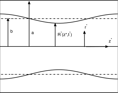
In this section, we provide the basic equations of motion and the boundary conditions for a model of airway closure in which the film consists of a single layer. We consider an axisymmetric configuration in a tube of radius a containing two immiscible fluids, the core fluid being air and occupying the region 0≤r*≤b and the other being an annular layerb≤r*≤a of non-Newtonian fluid coating the inner surface of the tube, as shown in Fig. 1. The air-core phase is assumed to be passive. The interface is perturbed from its equilibrium position, r*=b, so that it is located at r*=R*(z*,t*), where (r*,θ,z*) are the usual cylindrical coordinates and t* is time. The velocity in the film layer is defined by u*=(u*,0,w*), where u* and w* are the radial and axial components of velocity, the stress tensor is given by T*=−p*I+τ* where p* is the fluid pressure, and τ* is the deviatoric component of the stress tensor, which is defined below.
Figure 1.
Variables describing geometry of the air-liquid interface: r*=a is the tube radius, r*=b is the unperturbed location of the air-liquid interface, and r*=R*(z*,t*) denotes the perturbed position of the interface at time t*.
The liquid film continuity and momentum equations are
| (1) |
The Oldroyd-B model is used to describe the viscoelastic character of the liquid film. It assumes a diluted concentration of a polymer in a Newtonian solvent. A typical polymer chain is modeled as a linear elastic dumbbell, and with the aid of kinetic theory a constitutive equation can be derived to describe polymeric stresses.35 The stress tensor τ* is written as the sum of a Newtonian contribution connected with the solvent and a contribution S* due to the polymer,
| (2) |
where is the solvent viscosity. The tensor S* satisfies the following equation:
| (3) |
where Λ is a characteristic relaxation time and is the viscosity of the polymer. The above equations are solved subject to the boundary conditions described below. At the tube wall no-slip and penetration conditions are applied, so that
| (4) |
The stress and kinematic boundary conditions at the air-liquid interface are given by
| (5) |
where is the pressure of the air phase, which is assumed to be constant, is the unit normal vector pointing into the liquid film, κ*=∇*⋅n is the curvature of the interface, σ is the surface tension, which is assumed to be constant, and X*=⟨R*(z*,t*),θ,z*⟩ is a position vector defining the location of the air-liquid interface. Periodic boundary conditions are imposed at z*=0,L*, the tube ends,
| (6) |
LUBRICATION THEORY
In this section, lubrication theory is used to derive a system of simplified differential equations that describe the evolution of the air-liquid interface by assuming that the film thickness parameter ε=(a−b)∕a is small. Previous Newtonian models that predict plug formation20, 36 introduced a local radial coordinate y=(a−r*)∕ε and retained the leading order terms in ε in the momentum and continuity equations and boundary conditions but with two important exceptions. The curvature κ* was not expanded in powers of ε in the normal stress condition. In particular, the 1∕R* dependency in the transverse component of curvature was kept in the evolution equation. Also, the axisymmetric form of the kinematic boundary condition was used as opposed to the planar form, which is obtained at leading order in ε. In this paper, we do not replace the terms containing r* with the local coordinate y that appear in the governing equations and boundary conditions. The justification for doing this will be briefly discussed later in the validation Sec. 5A.
The governing equations and boundary conditions are nondimensionalized as follows:
| (7) |
where Ucap=ε3σ∕μ* is a capillary velocity scale and is the total viscosity. To leading order in ε, the momentum and continuity equations are given by
| (8) |
where . The constitutive Eq. 3 become
| (9) |
where We=ΛUcap∕a is the Weissenberg number and. The equation for Sθθ is not given since it is not required for the models considered in Secs. 3A, 3B. The tangential and normal stress boundary conditions 5 are given by the following expressions:
| (10) |
The kinematic boundary condition 5 can be written as
| (11) |
where is the axial flow rate in the film layer.
Small Weissenberg limit
In this section, we consider a weakly viscoelastic fluid, and assume that We⪡1. A regular perturbation scheme is used where all the dependent variables are expanded in power series in We in a manner similar to Ref. 32. The leading order problem corresponds to a Newtonian film coating the tube wall. The constitutive equations yield
| (12) |
The first two equations of Eq. 12 are substituted into the axial momentum Eq. 8 to yield
| (13) |
This is then integrated twice to yield the axial component of velocity,
| (14) |
where the stress free condition ∂w(0)∕∂r=0 has been applied at r=R(0). The radial component of velocity is determined from the continuity equation and is given by
| (15) |
The stress component is thus
| (16) |
The leading order evolution equation for R(0) is obtained by substituting w(0) into the kinematic boundary condition 11, and is given by
| (17) |
The order We momentum and continuity equations are of the same form as the leading order equations. The constitutive equations at this order can be written as
| (18) |
The interfacial boundary conditions 10 become
| (19) |
where is the axial flow rate correction and is the surface axial component of velocity. The stress component is determined from the constitutive Eq. 18,
| (20) |
is then obtained by substituting Eq. 20 into the axial momentum equation, integrating the resulting equation and applying the tangential stress condition atr=R(0),
| (21) |
The axial component of velocity w(1) is determined by integrating the constitutive equation for Eq. 18,
| (22) |
The axial flow rate is given by
| (23) |
which can then be substituted into the kinematic boundary condition 19 to yield an evolution equation for R(1). In the results section, the Oldroyd-B model derived above will be compared with the Jeffreys based model derived in the next section for arbitrary We.
Evolution equations for arbitrary We
In this section we relax the restriction that the Weissenberg number is small, and we follow the same approach taken by Refs. 33, 34 by assuming that τzr is the dominant component of the stress tensor and neglecting the other components and by neglecting the upper convective terms of the Oldroyd-B model. The first assumption about the shear stress is based on the scalings introduced in Eq. 7, which imply that and since ε⪡1. These inequalities suggest that the streamwise normal stress and the shear stress are the most dominant components of stress. In addition, the small We analysis performed in the previous section showed that there was no contribution to Szz at leading order. However, this does not fully justify the assumption of dropping Szz and neglecting the upper convective terms for arbitrary We. In the case where τzr is assumed to be dominant, the approximate axial and radial momentum equations and the continuity equation in the film region are
| (24) |
The linearized form of the constitutive Eq. 3 without the nonlinear upper convective terms is known as the Jeffreys model. For the shear component, Szr, it is given by
| (25) |
A constitutive equation for τzr can be obtained by applying the operator (1+We∂∕∂t) to τzr=εμs∂w∕∂r+Szr and by using Eq. 25,
| (26) |
where λ2=Weμs is known as the retardation parameter. Note that the Newtonian relationship between stress and rate of strain is recovered by setting We=0 (⇒λ2=0) in Eq. 26. The tangential and normal stress boundary conditions are given by the following expressions:
| (27) |
Since the pressure is independent of r, the axial momentum Eq. 24 can be integrated to obtain the following expression for τzr:
| (28) |
Note that a stress free boundary condition τzr=0 has been applied at r=R. An equation for the axial component of velocity is then obtained by substituting the latter into the constitutive Eq. 26 and integrating it,
| (29) |
The kinematic boundary condition can also be written as
| (30) |
where satisfies
| (31) |
and ws is the axial component of velocity evaluated at the interface r=R. We follow the approach taken in Ref. 33 to obtain an expression for ws. {There seems to be an error in the derivation of the evolution equation for the film thickness that is used to describe the rupture of a thin liquid layer found in Appendix B of Ref. 34. They derive an equation for the surface velocity by directly substituting the surface location [equivalent to r=R(z,t) in the current paper] into Eq. 29 without taking into account that (∂w∕∂z)|r=R(z,t)≠∂w|r=R(z,t)∕∂z} Equation 29 is integrated with respect to t,
| (32) |
where
Next, Eq. 32 is integrated by parts and then evaluated at r=R,
| (33) |
where and satisfy
| (34) |
In order to determine R(z,t), Eq. 30 is solved numerically subject to Eqs. 31, 33, 34.
LINEAR STABILITY ANALYSIS
A standard normal mode analysis can be used to investigate the effects of viscoelasticity using the Jeffreys model described in Sec. 3. Note that the Oldroyd-B model reduces to the Jeffreys model since the nonlinear upper-convective terms play no role since they are negligibly small when the base state is quiescent. We let
| (35) |
where k is the wave number of a disturbance wave on the air-liquid interface, g is the growth rate, and A is a small amplitude. Equation 35 is substituted into Eqs. 30, 31, 33, 34, which are then linearized in the limit ε→0. The growth rate satisfies the following quadratic equation:
| (36) |
Solving the above equation for the unstable root yields
| (37) |
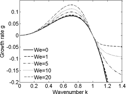
for λ2≠0. Figure 2 shows a plot of the growth rate versus the wave number for several values of We with the solvent viscosity μs=0.5. Instability occurs when g>0, that is for k in the range 0<k<1 for any We. The maximum growth rate occurs at , independent of We, and increases with We, indicating that viscoelastic effects are initially destabilizing. If λ2=0, corresponding to the simple Maxwell model, Eq. 36 only has one solution, and g is given by
| (38) |
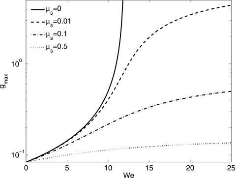
As for λ2≠0, instability occurs if 0<k<1, but only for small We. The maximum growth rate has a value of 1∕(12−We), which becomes unbounded at We=12. Similar results have been found by Ref. 34 who investigated the instability of a thin viscoelastic film, which ruptures due to van der Waals forces. This blow up corresponding to a nonphysical singularity at finite wave number can be removed by either including inertia or by considering the retarding effect of a solvent fluid (λ2>0).
Figure 2.
Results from normal mode analysis using the Jeffreys model with μs=0.5 showing how the growth rate g varies with wave number k for different values of We.
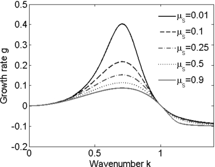
Figure 3 shows the effect of μr on g. For all μs>0,g≥0 in 0≤k≤1. As μs increases, the maximum growth rate, which occurs at , decreases. The variation of the maximum growth with respect to We is shown in Fig. 4 for different values of μs.
Figure 3.
The effect of the solvent viscosity μs=μ2∕We on the growth rate using the Jeffreys model, with We=15. Note that in the limit as μs→0 (λ2→0), the linear Maxwell model is recovered, and for this choice of We, the growth rate is singular at k=0.526 and k=0.851.
Figure 4.
The effect of the Weissenberg number We and the ratio of solvent viscosity to total viscosity μs on the maximum growth rate, gmax. Note that the linear Maxwell is obtained in the limit μs→0, and in this case gmax is singular at We=12. For μs>0 and any We the maximum growth rate remains finite.
NONLINEAR STABILITY RESULTS
The linear stability analysis described in Sec. 4 is only valid at early times when the disturbances are infinitesimally small. Nonlinear terms in the evolution equations derived in Sec. 3A for the small We Oldroyd-B model and in Sec. 3B for the arbitrary We Jeffreys model equation become important once the disturbances are not so small. These equations are solved numerically on a uniform grid covering the domain 0≤z≤L. In both cases, systems of algebraic and differential equations are obtained by replacing the spatial derivatives with fourth order finite differences. These systems are then solved numerically using DASPK,37, 38 a large scale differential algebraic system solver, in the domain 0≤z≤L subject to periodic boundary conditions. The initially flat interface is perturbed such that the initial condition for R takes the form
| (39) |
In all the computations A=0.01 and L=23∕2π is the most dangerous wavelength based on the linear stability theory presented in Sec. 4 for a Newtonian layer.
Validation
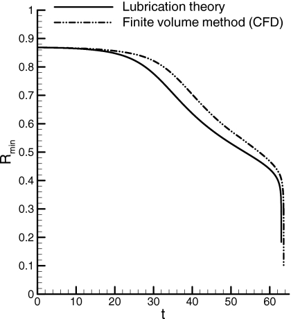
Gauglitz and Rakde31 showed numerically using a lubrication theory model that for the evolution of a Newtonian liquid layer, there is a critical value of ε, εc≈0.12, above which the liquid film breaks up, resulting in the formation of liquid plugs. We have confirmed this critical value by (i) using the lubrication theory model described in Sec. 3 and by (ii) solving numerically the Navier–Stokes and continuity equations together with the interfacial and boundary conditions 4, 5, 6 using the finite volume method. In Fig. 5 the minimum core radius Rmin=R(0,t) is plotted as a function of time t for a Newtonian liquid layer with ε=0.13. As can be seen, the lubrication theory model agrees very well with the direct numerical simulation, which was obtained by solving the Navier–Stokes equations and boundary conditions using a finite volume method.39 All the parameters in the finite volume simulation were the same as in the lubrication theory model except that unsteady effects were retained. The Ohnesorge number, , the ratio of viscous forces to inertial and surface tension forces was large, equal to 10. Also, this figure shows that evolution toward liquid plug formation (Rmin=0) is very fast once Rmin reaches approximately 0.4 so that the closure time can be fairly accurately predicted by solving the lubrication theory model.
Figure 5.
Minimum core radius vs time for a Newtonian liquid layer with ε=0.13. Comparison between lubrication theory model and numerical solution of the Navier–Stokes equations using a finite volume method.
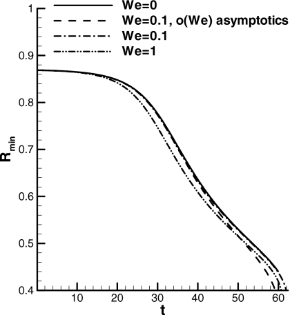
In order to validate the evolution equation based on the Jeffreys model derived in Sec. 3B, comparisons were made with the Oldroyd-B fluid model developed in Sec. 3A for small Weissenberg number. The solvent viscosity was chosen to be μs=0.5, based on rheological properties of biological fluids.32 As shown in Fig. 6, agreement is very good for small values of We. It is perhaps not too surprising that the two models agree when disturbances are initially small since this is when the upper-convective terms that appear in the Oldroyd-B model are negligible. Also at later times, for small We, the two models do not deviate too much from the Newtonian case. This figure also shows that Rmin decreases more rapidly for We≠0, which is consistent with the linear stability results presented in the previous section.
Figure 6.
The minimum core radius Rmin vs time t for a Newtonian fluid (solid line), an Oldroyd-B fluid with We=0.1 (dashed line) using the small We asymptotics of Sec. 3A, a Jeffreys fluid with We=0.1 (dash-dot line), and a Jeffreys fluid with We=1 (dash-dot-dot line). For the viscoelastic cases μs=0.5.
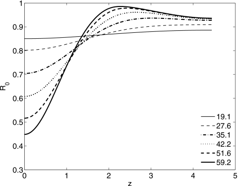
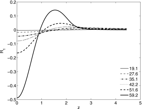
In Fig. 7, the evolution of a Newtonian liquid layer is shown, with ε=0.13, A=0.01, and L=23∕2π. As a result of the jump in normal stress due to surface tension, a pressure gradient is established in the liquid layer that drives flow into a growing bulge near z=0. The O(We) correction to the location of the interface R1 is plotted in Fig. 8 at the same times as the leading order profiles shown in Fig. 7. Near the growing bulge R1(z,t)<0, implying that the instability is more severe for a viscoelastic layer (with We≠0). By mass conservation, R1 has to be positive in parts of the domain, implying that the viscoelastic layer thins more rapidly in places than a Newtonian layer.
Figure 7.
Evolution of a Newtonian liquid layer. The location of the air-liquid interface R(z,t) is plotted as a function of z, for 0≤z≤L∕2 at the times indicated in the figure legend. Here ε=0.13, A=0.01, L=23∕2π.
Figure 8.
The order We correction to the location of the air-liquid interface as a function of z at the same times as in the previous figure and for the same ε using the small We Oldroyd-B model. Here μs=0.5.
Nonlinear stability results for arbitrary We
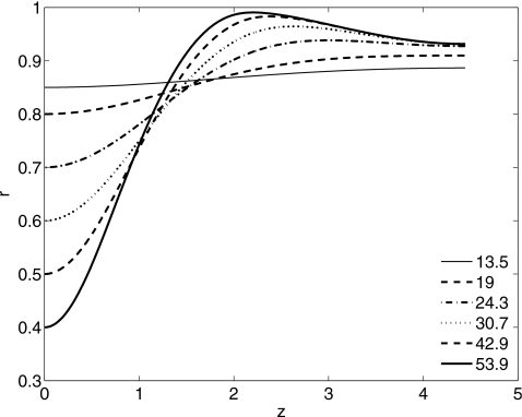
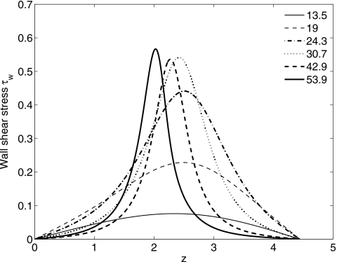
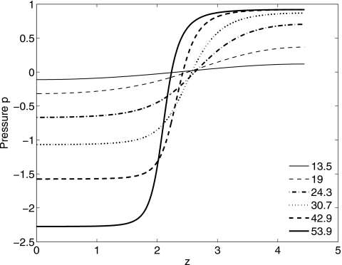
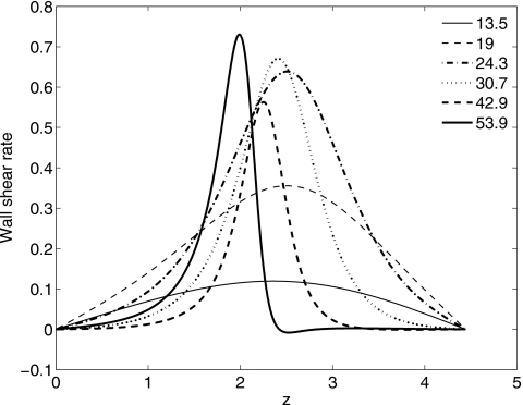
In this section, we present results for arbitrary We using the Jeffreys (λ2≠0) models. Figure 9 shows a typical evolution of the interface for a non-Newtonian layer with ε=0.13, We=10, and μs=0.5. As with the small We Oldroyd-B model, a growing lobe forms near z=0 as fluid drains into it. At early times, this flow is strongly dependent on We and μs, and is quite slow for quite small We and∕or large μs (see Fig. 13 later). It is also slow once the film layer becomes very thin (but before closure occurs). The wall shear stress τw=τzr|r=1 Eq. 28, the pressure p given by Eq. 27, and the wall shear rate ε∂w∕∂r|r=1 are shown in Figs. 101112, respectively. The maximum τw and pressure gradient increase with time and occur where the film layer is thinnest. There are two constant pressure regions corresponding to two growing lobes, where the velocity must be quite small. The larger lobe eventually blocks the air-core phase. It can be inferred from Figs. 1012 that the apparent viscosity, the ratio of shear stress to shear rate, can be less than one in the bulge region, suggesting that the rate of filling of the bulge for a viscoelastic layer is faster than that of a Newtonian layer.
Figure 9.
Air liquid interface R(z,t) plotted as a function of z at different times (shown in the figure) during evolution toward closure for a Jeffreys fluid. Here ε=0.13, We=10, μs=0.5.
Figure 13.
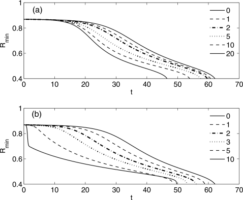
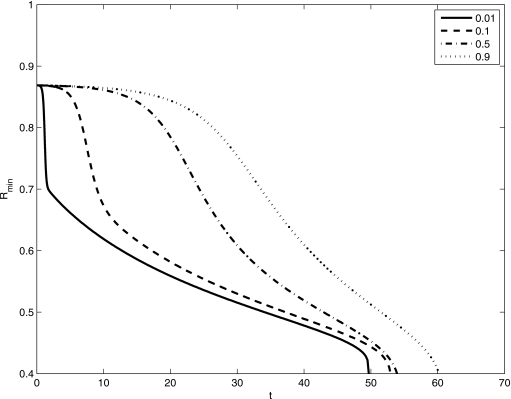
The effect of the Weissenberg number We on the minimum core radius Rmin=R(0,t), for two different solvent viscosities (a) μs=0.5 and (b) μs=0.01. The film thickness parameter is ε=0.13.
Figure 10.
The wall shear stress τw as a function of z at different times (indicated in the figure). The parameters are the same as Fig. 9.
Figure 11.
The film pressure p vs z for the same parameter values as in the previous figure.
Figure 12.
Wall shear rate vs z for the same parameters as in Fig. 9.
Closure, or tube occlusion, occurs if Rmin=R(0,t)→0 in finite time, and this is provided there is sufficient fluid in the film layer. In Figs. 13a, 13b, Rmin is plotted as a function of time for different values of We using the Jeffreys model with (a) μs=0.5 and (b) μs=0.01. The film thickness parameter is ε=0.13. (Note that the We=0 case corresponds to a Newtonian liquid layer.) These figures show that the initial growth rate increases with We, which is consistent with the linear stability results of the previous section and that Rmin→0 faster as We increases. This indicates that a more viscoelastic fluid drains more quickly into the dominant growing bulge at z=0 and reaches the critical volume required for closure more quickly. The influence of μs on Rmin is particularly noticeable for large We and small μs at early times as displayed in Fig. 14 for We=10 and ε=0.13. As μs decreases the initial growth rate increases. This is because the film reacts like a solid as opposed to a viscous fluid. At larger times, this behavior changes, and the film behaves more like a viscous fluid.
Figure 14.
The effect of solvent viscosity μs on Rmin using the Jeffreys model derived in Sec. 3B. Here ε=0.13, We=10.
In order to examine the effect of the film thickness parameter ε on the closure time it is convenient to introduce new parameters and variables that do not depend on ε. We define a time scale Ts=aμ∕σ so that the original time scale Tcap=Ts∕ε3. The Weissenberg number We(ε)=λ∕Tcap is also dependent on ε. Therefore, when varying ε, the Weissenberg number changes in the following way:
where . We chose εref=0.12 in the results shown below.
Airway closure normally occurs toward the end of expiration since this is when ε reaches its maximum value (i.e., when the airway radius attains its minimum). Therefore, it seems reasonable to stipulate that airway closure must happen within one breath. The closure time Tc is defined to be the time taken for Rmin(Tc)=0. Also, due to the periodic nature of the breathing cycle, Tc≤Tb, where Tb is the time taken for one breath. It is not possible to compute Tc exactly and the lubrication theory model breaks down once Rmin becomes small. Instead we choose the following definition:
For the time being we relax this definition and do not apply the second inequality, which specifically applies to pulmonary airway closure, and discuss its consequences in the next section.
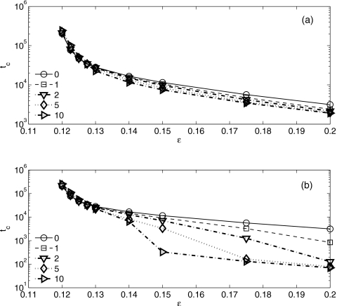
As shown earlier, direct numerical simulations of the Newtonian case reveal that the evolution toward closure is very fast once Rmin reaches 0.4 for small values of ε, such as ε=0.13. This suggests that the closure time can be accurately extrapolated once Rmin reaches 0.4. In Figs. 15a, 15b the closure time tc=Tc∕ε3 is plotted as function of the film thickness parameter ε for different Weref and μs. For fixed Weref, tc decreases with increasing ε. For small ε, tc increases slightly with increasing Weref, but for larger ε tc decreases with increasing Weref, which is consistent with the results shown in Fig. 9. For moderate ε there is a significant drop in tc at large Weref provided μs is fairly small [see Fig. 15b]. At larger ε≈0.2, even for small μs, tc is not strongly dependent on Weref, indicating the strong influence of surface tension.
Figure 15.
The influence of We and ε on the closure time tc for two different solvent viscosities (a) μs=0.5 and (b) μs=0.01.
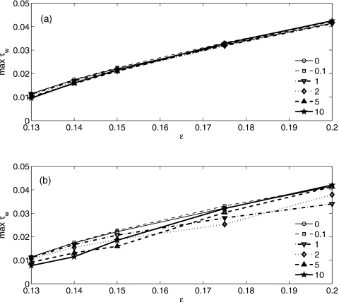
In Fig. 16 the maximum wall shear stress evaluated when Rmin reaches 0.4 is shown to increase with increasing ε. For large μs, Weref has no significant effect on τw, as indicated by Fig. 16a. However, as shown in Fig. 16b, for small ε and μs τw decreases with increasing Weref, but for large ε≈0.2, there is no significant difference between the Newtonian case and large Weref≥5.
Figure 16.
Influence of the film thickness parameter ε and the Weissenberg number Weref on the maximum wall shear stress τw, for two different solvent viscosities (a) μs=0.5 and (b) μs=0.01.
APPLICATION TO PULMONARY AIRWAY CLOSURE
In the results section we defined the closure time Tc such that Rmin(Tc)≤0.4 and Tc≤Tb without applying the second inequality. Here we discuss its significance as it relates to airway closure. The value of Tb can vary significantly between adults and neonates. Adults typically breathe 12–16 breaths per minute while neonates breathe between 40 and 70 breaths per minute.40 Therefore, the dimensional breath cycle ranges from 0.86 to 5 s. In order to estimate dimensional values for closure time from the values of tc shown in Fig. 15, we also need to specify the viscosity of the liquid layer μ*, the tube radius a, and the surface tension σ. The viscosity of mucus ranges from 100 Poise to 10 000 Poise. So it is reasonable to expect that the effective viscosity of the airway liquid is somewhat smaller due to the presence of the periciliary liquid. In a study of surfactant spreading on a viscoelastic liquid layer,32 was chosen to be approximately 0.01 Poise and .41 The airway radius, , which decreases with airway generation number n, can be approximated using the following formula:42
where is the radius of an adult trachea. We choose the surface tension to be σ=20 dynes∕cm. If we set and consider airway generation 12 with , the time scale . Therefore, Tb=3520 for a typical breath that lasts 5 s. According to the results presented in Fig. 15b, closure can occur for any value of Weref provided ε≥0.18, and does not occur within 5 s if ε<0.14 for the values of Weref that were considered. For intermediate values of ε, 0.14<ε<0.18, closure can occur provided Weref is sufficiently large. At the other extreme, for a much less viscous polymer, say, Ts≈2.8×10⁻⁵ s and Tb≈1.8×10⁵. Consequently closure can occur for most of the chosen values of ε displayed in Fig. 15a. These conclusions about closure depend on the value of Tb, which critically depends on the time for one breath, the airways radius (generation), the film viscosity, and the surface tension. A decrease in Tb has a “stabilizing” effect. This occurs if either the airway radius or the film viscosity increases, or the surface tension decreases.
The maximum wall shear stress during the closure event can also be estimated. The capillary pressure scale is , and based on the results shown in Fig. 16, . These levels are somewhat smaller than those that cause epithelial cell damage43, 44 because the computed stresses shown in Fig. 16 were evaluated when Rmin=0.4. However, stress levels of this magnitude are thought to stimulate physiologic responses. For example, the major cytoskeletal components of alveolar epithelial cells can be disassembled by shear stresses of the order of 30 dynes∕cm2.45 It is also well known that biochemical and electrical signals can be induced by fluid stresses on endothelial cells. This phenomenon is known as mechanotransduction.46
CONCLUSIONS
In this paper we investigated the stability of a viscoelastic liquid layer coating the inner surface of a rigid cylindrical tube as a simplified model of airway closure, focusing on the viscoelastic character of the liquid layer. Several different constitutive equations were used to model the viscoelastic fluid. One model used the Oldroyd-B equation, which includes upper convective terms. Combined with lubrication theory, a regular perturbation analysis for small We was carried out, from which a set of evolution equations for the film thickness were obtained. The other model that was considered used the Jeffreys constitutive equation, and did not include the nonlinear upper-convective terms. For the linear constitutive model, a system of four coupled partial differential equations was derived using lubrication theory that describes the evolution of the air-liquid interface and the axial flow rate of the film layer for arbitrary We.
A linear stability analysis was performed to investigate the initial temporal growth of a sinusoidal small amplitude perturbation. In the very early stages of growth, the Oldroyd-B and Jeffreys models behave in a similar fashion since the nonlinear upper convective terms are negligibly small. For the Jeffreys model, the system is unstable for the same range of wave numbers as a Newtonian fluid and the maximum growth rate increases with We implying that viscoelasticity is initially destabilizing. As the solvent viscosity parameter μs decreases the maximum growth rate increases. The linear Maxwell model is obtained in the limit as μs→0. For μs=0 and We≥12, a singularity appears, and the growth rate can become unbounded at some finite wavelength. When We⪢1, the relaxation time scale is much larger than the capillary-viscous time scale, and the response of the polymeric fluid in the film layer to an interfacial perturbation can be instantaneous like that of an elastic material (see also Ref. 34). A similar singularity was obtained by Halpern and Grotberg20 who investigated the stability of a liquid-lined elastic tube with and without wall damping. The singularity disappears when the Jeffreys model is used instead of the linear Maxwell model since the effect of a solvent is included, which provides viscous damping.
The nonlinear simulations yielded several interesting results. For sufficiently small values of ε<0.119, closure does not occur within a breathing cycle . This result seems to be unaffected by viscoelasticity, and is due to the fact that the film layer becomes exceedingly thin with time and the draining flow into larger growing bulge is very slow. For intermediate values of ε, closure time can be significantly affected by viscoelasticity. For example, from the results shown in Fig. 15b, tc∼2×10² for Weref=10, but tc∼104 for Weref≈1. We also examined the influence of the film thickness parameter ε and the Weissenberg number We on the maximum shear stress evaluated at the tube wall, max(τw), because of its potential impact on cell damage. We found that max(τw) increases with ε for fixed We due to the greater destabilizing effect of surface tension and larger flows within the layer, and that it decreases with increasing We for small ε provided μs is sufficiently small. For large ε≈0.2, there was no significant difference between the Newtonian flow case and the large We case.
Finally, we would like to make a few concluding remarks about some of the underlying assumptions. The lubrication theory models presented in this paper will ultimately break down. This is true for a Newtonian liquid layer as well as a viscoelastic one. Once the layer becomes sufficiently thick and the flow layer sufficiently large, some of the neglected viscous, unsteady, and convective terms become important. In addition, for a viscoelastic liquid layer described by the Oldroyd-B constitutive relation, the upper convective terms will ultimately become important and have to be incorporated in order to fully understand the complete dynamics of airway closure.
ACKNOWLEDGMENTS
We acknowledge support from the National Institutes of Health Grant No. NIH HL85156.
References
- Yager D., Cloutier T., Feldman H., Bastacky J., Drazen J. M., and Kamm R. D., “Airway surface liquid thickness as a function of lung volume in small airways of the guinea pig,” J. Appl. Physiol. 77, 2333 (1994). [DOI] [PubMed] [Google Scholar]
- Codd S. L., Lambert R. K., Alley M. R., and Pack R. J., “Tensile stiffness of ovine tracheal wall,” J. Appl. Physiol. 76, 2627 (1994). 10.1063/1.357559 [DOI] [PubMed] [Google Scholar]
- Sackner M. A. and Kim C. S., “Phasic flow mechanisms of mucus clearance,” Eur. J. Respir. Dis. Suppl. 153, 159 (1987). [PubMed] [Google Scholar]
- Widdicombe J. H., Bastacky S. J., Wu D. X. Y., and Lee C. Y., “Regulation of depth and composition of airway surface liquid,” Eur. Respir. J. 10, 2892 (1997). 10.1183/09031936.97.10122892 [DOI] [PubMed] [Google Scholar]
- Yeates D. B., in The Lung: Scientific Foundations, edited by Crystal R. G. and West J. B. (Raven, New York, 1990), Vol. 1, p. 197. [Google Scholar]
- Quraishi M. S., Jones N. S., and Mason J., “The rheology of nasal mucus: A review,” Clin. Otolaryngol. 23, 403 (1998). 10.1046/j.1365-2273.1998.00172.x [DOI] [PubMed] [Google Scholar]
- Basser P. J., McMahon T. A., and Griffith P., “The mechanism of mucus clearance in cough,” J. Biomech. Eng. 111, 288 (1989). 10.1115/1.3168381 [DOI] [PubMed] [Google Scholar]
- Macklem P. T., Proctor D. F., and Hogg J. C., “The stability of peripheral airways,” Respir. Physiol. 8, 191 (1970). 10.1016/0034-5687(70)90015-0 [DOI] [PubMed] [Google Scholar]
- Greaves I. A., Hildebrandt J., and Hoppin J. F. G., Handbook of Physiology (American Physiological Society, Bethesda, MD, 1986), Vol. 3, Chap. 14. [Google Scholar]
- Everett D. H. and Haynes J. M., “Model studies of capillary condensation 1. Cylindrical pore model with zero contact angle,” J. Colloid Interface Sci. 38, 125 (1972). 10.1016/0021-9797(72)90228-7 [DOI] [Google Scholar]
- Kamm R. D. and Schroter R. C., “Is airway closure caused by a thin liquid instability?” Respir. Physiol. 75, 141 (1989). 10.1016/0034-5687(89)90059-5 [DOI] [PubMed] [Google Scholar]
- Mansell A., Bryan C., and Levison H., “Airway closure in children,” J. Appl. Physiol. 33, 711 (1972). [DOI] [PubMed] [Google Scholar]
- Anthonisen N. R., Danson J., Robertson P. C., and Ross W. R. D., “Airway closure as a function of age,” Respir. Physiol. 8, 58 (1969). 10.1016/0034-5687(69)90044-9 [DOI] [PubMed] [Google Scholar]
- Crawford A. B. H., Cotton D. J., Paiva M., and Engel L. A., “Effect of airway closure on ventilation distribution,” J. Appl. Physiol. 66, 2511 (1989). 10.1063/1.344264 [DOI] [PubMed] [Google Scholar]
- Frazer D. G., Weber K. C., and Franz G. N., “Evidence of sequential opening and closing of lung units during inflation-deflation of excised rat lungs,” Respir. Physiol. 61, 277 (1985). 10.1016/0034-5687(85)90071-4 [DOI] [PubMed] [Google Scholar]
- Schurch S., Bachofen H., Goerke J., and Possmayer F., “A captive bubble method reproduces the in situ behavior of lung surfactant monolayers,” J. Appl. Physiol. 67, 2389 (1989). [DOI] [PubMed] [Google Scholar]
- Liu M., Wang L., Li E., and Enhorning G., “Pulmonary surfactant will secure free airflow through a narrow tube,” J. Appl. Physiol. 71, 742 (1991). [DOI] [PubMed] [Google Scholar]
- Synek M., Beasley R., Goulding D., Holloway L., and Holgate S. T., “The distribution of airways mucus plug occlusion in fatal asthma,” Clin. Exp. Allergy 24, 194 (1994). [Google Scholar]
- Johnson M., Kamm R. D., Ho L. W., Shapiro A., and Pedley T. J., “The nonlinear growth of surface-tension-driven instabilities of a thin annular film,” J. Fluid Mech. 233, 141 (1991). 10.1017/S0022112091000423 [DOI] [Google Scholar]
- Halpern D. and Grotberg J. B., “Fluid-elastic instabilities of liquid-lined flexible tubes,” J. Fluid Mech. 244, 615 (1992). 10.1017/S0022112092003227 [DOI] [PubMed] [Google Scholar]
- Halpern D. and Grotberg J. B., “Surfactant effects on fluid-elastic instabilities of liquid-lined flexible tubes: A model of airway closure,” J. Biomech. Eng. 115, 271 (1993). 10.1115/1.2895486 [DOI] [PubMed] [Google Scholar]
- D. R.Otis, Jr., Johnson M., Pedley T. J., and Kamm R. D., “Role of pulmonary surfactant in airway closure: A computational study,” J. Appl. Physiol. 75, 1323 (1993). [DOI] [PubMed] [Google Scholar]
- Hill M. J., Wilson T. A., and Lambert R. K., “Effects of surface tension and intraluminal fluid on mechanics of small airways,” J. Appl. Physiol. 82, 233 (1997). [DOI] [PubMed] [Google Scholar]
- Cassidy K. J., Halpern D., Ressler B. G., and Grotberg J. B., “Surfactant effects in model airway closure experiments,” J. Appl. Physiol. 87, 415 (1999). [DOI] [PubMed] [Google Scholar]
- Heil M., “Airway closure: Occluding liquid bridges in strongly buckled elastic tubes,” J. Biomech. Eng. 121, 487 (1999). 10.1115/1.2835077 [DOI] [PubMed] [Google Scholar]
- Heil M., “Minimal liquid bridges in nonaxisymmetrically buckled elastic tubes,” J. Fluid Mech. 380, 309 (1999). 10.1017/S0022112098003760 [DOI] [Google Scholar]
- Halpern D. and Grotberg J. B., “Nonlinear saturation of the Rayleigh instability due to oscillatory flow in a liquid-lined tube,” J. Fluid Mech. 492, 251 (2003). 10.1017/S0022112003005573 [DOI] [Google Scholar]
- Campana D., Di Paolo J., and Saita F. A., “A 2D model of Rayleigh instability in capillary tubes—surfactant effects,” Int. J. Multiphase Flow 30, 431 (2004). 10.1016/j.ijmultiphaseflow.2004.03.007 [DOI] [Google Scholar]
- Hazel A. L. and Heil M., “Surface-tension-induced buckling of liquid-lined elastic tubes: A model for pulmonary airway closure,” Proc. R. Soc. London, Ser. A 461, 1847 (2005). 10.1098/rspa.2005.1453 [DOI] [Google Scholar]
- Hammond P. S., “Nonlinear adjustment of a thin annular film of viscous fluid surrounding a thread of another within a circular pipe,” J. Fluid Mech. 137, 363 (1983). 10.1017/S0022112083002451 [DOI] [Google Scholar]
- Gauglitz P. A. and Radke C. J., “An extended evolution equation for liquid film breakup in cylindrical capillaries,” Chem. Eng. Sci. 43, 1457 (1988). 10.1016/0009-2509(88)85137-6 [DOI] [Google Scholar]
- Zhang Y. L., Matar O. K., and Craster R. V., “Surfactant spreading on a thin weakly viscoelastic film,” J. Non-Newtonian Fluid Mech. 105, 53 (2002). 10.1016/S0377-0257(02)00061-7 [DOI] [Google Scholar]
- Rauscher M., Munch A., Wagner B., and Blossey R., “A thin-film equation for viscoelastic liquids of Jeffreys type,” Eur. Phys. J. E 17, 373 (2005). 10.1140/epje/i2005-10016-8 [DOI] [PubMed] [Google Scholar]
- Tomar G., Shankar V., Shukla S. K., Sharma A., and Biswas G., “Instability and dynamics of thin viscoelastic liquid films,” Eur. Phys. J. E 20, 185 (2006). 10.1140/epje/i2006-10011-7 [DOI] [PubMed] [Google Scholar]
- Huilgol R. R. and Phan-Thien N., Fluid Mechanics of Viscoelasticity: General Principles, Constitutive Modeling, Analytical and Numerical Techniques (Elsevier, Amsterdam, New York, 1997). [Google Scholar]
- Gauglitz P. A. and Radke C. J., “The dynamics of liquid film breakup in constricted cylindrical capillaries,” J. Colloid Interface Sci. 134, 14 (1990). 10.1016/0021-9797(90)90248-M [DOI] [Google Scholar]
- Brown P. N., Hindmarsh A. C., and Petzold L. R., “Using Krylov methods in the solution of large-scale differential-algebraic systems,” SIAM J. Sci. Comput. 15, 1467 (1994). 10.1137/0915088 [DOI] [Google Scholar]
- Brown P. N., Hindmarsh A. C., and Petzold L. R., “Consistent initial condition calculation for differential-algebraic systems,” SIAM J. Sci. Comput. (USA) 19, 1495 (1998). 10.1137/S1064827595289996 [DOI] [Google Scholar]
- Fujioka H., Takayama S., and Grotberg J. B., “Unsteady propagation of a liquid plug in a liquid-lined straight tube,” Phys. Fluids 20, 062104 (2008). 10.1063/1.2938381 [DOI] [PMC free article] [PubMed] [Google Scholar]
- Seikel J. A., Drumright D. G., and Seikel P., Essentials of Anatomy and Physiology for Communication Disorders (Thomson∕Delmar Learning, Clifton Park, NY, 2004). [Google Scholar]
- Silberberg A., “Biorheological matching—mucociliary interaction and epithelial clearance,” Biorheology 20, 215 (1983). [DOI] [PubMed] [Google Scholar]
- Weibel E. R. and Gomez D. M., “Architecture of the human lung,” Science 137, 577 (1962). 10.1126/science.137.3530.577 [DOI] [PubMed] [Google Scholar]
- Bilek A. M., Dee K. C., and Gaver D. P., “Mechanisms of surface-tension-induced epithelial cell damage in a model of pulmonary airway reopening,” J. Appl. Physiol. 94, 770 (2003). 10.1063/1.1582234 [DOI] [PubMed] [Google Scholar]
- Huh D., Fujioka H., Tung Y. C., Futai N., Paine R., Grotberg J. B., and Takayama S., “Acoustically detectable cellular-level lung injury induced by fluid mechanical stresses in microfluidic airway systems,” Proc. Natl. Acad. Sci. U.S.A. 104, 18886 (2007). 10.1073/pnas.0610868104 [DOI] [PMC free article] [PubMed] [Google Scholar]
- Ridge K. M., Linz L., Flitney F. W., Kuczmarski E. R., Chou Y. H., Omary M. B., Sznajder J. I., and Goldman R. D., “Keratin 8 phosphorylation by protein kinase C delta regulates shear stress-mediated disassembly of keratin intermediate filaments in alveolar epithelial cells,” J. Biol. Chem. 280, 30400 (2005). 10.1074/jbc.M504239200 [DOI] [PubMed] [Google Scholar]
- Davies P. F., “Flow-mediated endothelial mechanotransduction,” Physiol. Rev. 75, 519 (1995). [DOI] [PMC free article] [PubMed] [Google Scholar]


