

Abstract
We studied the coordinated action of fingers during static tasks involving exertion of force and torque on a handheld object. Subjects were asked to keep a handle with an attachment that allowed for independent change of the suspended load (0.5–2.0 kg) and external torque (0.375–1.5 N m) in a vertical position while applying minimal effort. Normal and shear forces were measured from the thumb; normal forces only were measured from the four fingers.
Experimental results
(1) the thumb shear force increased during supination efforts and decreased during pronation efforts; (2) the total moment of the normal finger forces only counterbalanced approximately 50% of the external torque, hence shear forces accounted for approximately one-half of the total torque exerted on the object; (3) the total normal force increased with external torque, and the total force magnitude did not depend on the torque direction; (4) the forces of the ‘peripheral’ (index and little) fingers depended mainly on the torque while the forces exerted by the ‘central’ (middle and ring) fingers depended both on the load and torque; (5) there was a monotonic relationship between the mechanical advantage of a finger (i.e., its moment arm during torque production) and the force produced by that finger; and (6) antagonist finger moments acting opposite to the intended direction of the total moment were always observed –at low torques the antagonist moments were as high as 40–60% of the agonist moments.
Modeling
A three-zone model of coordinated finger action is suggested. In the first zone of load/torque combinations, activation of antagonist fingers (i.e., fingers that generate antagonist moments) is necessary to prevent slipping. In the second zone, the activity of agonist fingers is sufficient for preventing slips. In the third zone, the performer has freedom to choose between either activating the antagonist fingers or redistributing activities amongst the agonist fingers. The findings of this study provide the foundation for neural network and optimization modeling described in the companion paper
1 Introduction
When manipulating a handheld object, for instance when drinking from a glass, one needs to apply sufficient grip force to prevent the glass from slipping out of the hand. In addition, one needs to control the total torque exerted by all fingers such that the glass remains either vertical (in this case the torque magnitude about the point of thumb contact should equal zero) or at a controlled angle that is suitable for drinking and preventing the liquid from being spilled. Usually, the requirements for grip force stabilization allow for some laxity, while the requirements for total torque production are highly specified. As in the example of drinking from a glass, the grip force needs only to be larger than the slip threshold and smaller than the force that would break the glass. In contrast, the torque applied to the glass needs to be precisely controlled since any error will lead to rotation of the glass and spilling of the liquid.
During manipulation of the glass, the fingers may act as force agonists and torque antagonists. To prevent the glass from slipping, the fingers act as agonists; each of them contributes to the total grip force. In contrast, the index and middle fingers and the ring and little fingers exert moments of force in opposite directions about a pivot point created by the thumb. These two pairs of fingers are torque antagonists. To minimize the total finger force, the fingers that generate a moment opposite to the intended moment should not produce any force. At the same time, to prevent the object from slipping they may be required to generate a force that contributes to the total grip force. The central nervous system (CNS) must somehow find a balance between these conflicting requirements.
Because a set of five digits is redundant for the control of a handheld object, the effort can be distributed among the involved fingers in many different ways. As such, this task is a particular example of the notorious problem of motor redundancy (also known as Bernstein’s problem; see Bernstein 1947, 1967; Turvey 1990). One purpose of the current line of research is to discover criteria that are used by the CNS in generating particular motor patterns for redundant tasks (also see Li et al. 1998).
Investigations on torque production during grasping are scarce; grasping studies have mainly addressed slip force and slip prevention. Slip force Fsl is the minimal grasp force that is necessary to prevent an object from slipping out of the hand (Johansson and Westling 1984; Johansson et al. 1999). In these experiments, subjects grasped objects with the tips of the index finger and thumb (Kinoshita et al. 1997; Goodwin et al. 1998; Johansson et al. 1999). Force sharing –the distribution of the total force produced among the fingers involved in a task –was not discussed in these studies. In a recent experiment performed by Santello and Soechting (2000), subjects were asked to hold a handle for 30 s. In different trials, the location of the center of mass of the handle was changed; this caused the external torque to vary. The study focused mainly on the continuous oscillations of the individual finger forces during the holding period. It was demonstrated that, in all frequency bands, the oscillations of the different finger forces were synchronous and, hence, determined by a multifinger synergy.
The present study addresses forces exerted by five digits on a handheld object during static force and torque production tasks. We are interested primarily in strategies used by the CNS to fulfill the apparently conflicting force and torque production requirements. The study consists of two parts. In Part I (this paper) the experimental methods are described and biomechanical data are presented. Part II (Zatsiorsky et al. 2002) analyzes torque control using an expanded version of a neural network approach developed previously to analyze multifinger force production tasks (Zatsiorsky et al. 1998). In particular, we use the network to reconstruct the neural commands sent to individual fingers.
2 Methods
We studied a prismatic precision grip task, that is, a grip configuration in which the tips of the fingers and thumb oppose each other (Cutkosky and Wright 1986). In the experiment, subjects were required to stabilize a handle with an attachment that allowed for independent changes of the suspended load and external torque (Fig. 1).
Fig. 1.

Experimental ‘inverted-T’ handle/beam apparatus. The force components in the X and Y directions are called normal and shear forces, respectively. Subjects maintained the handle in the upright position using minimal force (Note that the figure is not drawn to scale.)
2.1 Subjects
Eighteen right-hand-dominant males (mean ± SD: age, 25.0 ± 5.0 years; mass, 80.0 ± 10.0 kg; height, 178.0 ± 10.0 cm; hand length, 19.0 ± 2.0 cm; and hand breadth, 8.6 ± 0.4 cm) participated in this study. None of the subjects had any previous history of neuropathies or traumas to their upper extremities. All of the subjects gave informed consent according to procedures established by the Office for Regulatory Compliance at The Pennsylvania State University.
2.2 Equipment
Four uniaxial force transducers (208A03, PCB Piezotronics, Depew, N.Y.) and one six-axis force/torque transducer (Nano-17, ATI Industrial Automation, Garner, N.C.) were used to measure the forces of the fingers and thumb, respectively. The transducers were mounted on an aluminum handle. The handle was fixed to the top edge of an aluminum beam and positioned at the midpoint of the beam. The center points of each of the finger transducers were located 25 mm apart in the vertical direction; the thumb transducer was located at the midpoint of the handle in the vertical direction. The center points of the index and middle finger transducers were located 37.5 mm and 12.5 mm, respectively, above the center point of the thumb transducer; the center points of the ring and little fingers were located 12.5 mm and 37.5 mm, respectively, below the center point of the thumb transducer. Aluminum plates (18.5 mm × 25.0 mm) were mounted on the transducers in order to provide a surface for finger contact; the surfaces of the plates were covered with 100-grit sandpaper. The horizontal distance between the grasping surfaces of the finger and thumb transducers was 56.5 mm. A circular level was attached to the top of the handle in order to monitor the pitch and roll of the handle/beam apparatus. In addition, two vertically oriented rods positioned at both ends of the beam constrained the motion of the beam to prevent excessive yaw. A weight hanger was suspended from an eyehook attached to the beam; the total mass of the handle/beam apparatus could be changed by varying the mass placed on the hanger. A slot running the length of the beam allowed the weight hanger to be moved along the beam; the external torque exerted on the handle/beam apparatus could be changed by varying the position of the suspended mass in relation to the handle. The mass of the handle/beam apparatus by itself (without an external load) was 1.0 kg.
The finger transducers were connected in series with separate ICP power and amplifying units (484B06, PCB Piezotronics). The output signals of the finger and thumb transducers were sent to a 12-bit analog/digital converter (AT-MIO-64F-5, National Instruments, Austin, Tex.) and a 16-bit ISA bus controller (F/T-16, ATI Industrial Automation), respectively, interfaced with a personal computer (P5-133, Gateway; North Sioux City, S.D.). The data were collected at 100 Hz and filtered at 5 Hz using a fourth-order low-pass Butterworth filter.
2.3 Experimental procedures
Subjects were seated in a chair alongside a table with the upper arm positioned at approximately 45° abduction in the frontal plane and 45° flexion in the sagittal plane. The elbow joint was flexed approximately 45°. The forearm was pronated 90° so that the hand was placed in a natural grasping position. Two lashing straps were used to fasten subjects’ forearms to a foam-covered board in order to maintain a constant configuration of the arm throughout the experiment. The arm was positioned so that the hand and wrist extended over the edge of the table to allow for grasping.
Prior to the first test session, subjects participated in an orientation session to become familiar with the handle/beam apparatus and to ensure that they would be able to accomplish the experimental tasks. During the first of two test sessions, subjects performed torque-production tasks. Four different masses (0.5 kg, 1.0 kg, 1.5 kg, and 2.0 kg) were suspended from the beam at different positions with respect to the handle in order to exert torques of 0 N m, 0.375 N m, 0.75 N m, 1.125 N m, and 1.5 N m on the handle/beam apparatus in both clockwise (CW) and counterclockwise (CCW) directions. According to the coordinate system used in this experiment, a CW torque resulted in supination of the hand and wrist, necessitating a counterbalancing pronation torque to maintain the handle in an upright position. Likewise, a CCW torque caused pronation of the hand and wrist, requiring a counterbalancing supination torque to keep the handle in a vertical orientation. There were 36 conditions in all: CW and CCW rotations were both exerted on the handle/beam apparatus in 16 trials (four loads × four torques), while zero external torque conditions were present in four trials (four loads). The conditions were presented in a balanced order.
At the beginning of each trial, subjects were instructed to grasp the handle, which was oriented vertically. When subjects indicated their readiness, a load was suspended from the beam. Subjects were instructed to use the minimal force necessary to stabilize the handle in a vertical position, while at the same time preventing the handle from slipping in the vertical direction. Subjects were not directed to use any particular combination of finger forces in order to achieve these goals. Once the finger force fluctuations stabilized and subjects verbally expressed that they were using the minimal force necessary to stabilize the handle, the trial was ended. The force values of the individual fingers were recorded at the instant when the smallest total force was produced. Note that we studied static tasks and minute finger force fluctuations were not an object of the analysis. Typically, subjects required 2–3 s to produce the moment necessary to return the handle to the vertical position and an additional 7–10 s to reach the minimum total force. A 3-min break was given after each trial to avoid fatigue.
During the second test session, subjects performed maximal four-finger and individual finger-force tasks. These trials utilized the same handle/beam apparatus as used in the torque-production tasks. However, the handle was fixed vertically to prevent rotation. In the maximal four-finger force task, subjects were asked to produce as large a force as possible using the index, middle, ring, and little fingers simultaneously; subjects were not directed to use any particular combination of finger forces to achieve this goal. The force values of the individual fingers were recorded at the instant when the largest total force was produced. In the maximal individual-finger force task, subjects were asked to produce as large a force as possible using either the index, middle, ring, or little finger by itself. The largest force value of the finger was recorded. Subjects were given two attempts at each task; the maximal force values were averaged across the two attempts. Typically, subjects required 2–5 s to produce the maximal finger force values. In addition, an estimation of the coefficient of friction between the skin of the fingertips and the sandpaper covering the grasping surfaces of the handle was performed. The friction coefficient μ was determined to be 1.72; the friction coefficient determination is described elsewhere (Gregory 2002).
3 Experimental results
We use the term moment for designating a moment of force exerted by a finger force(s) about a pivot point at the center of the thumb transducer. The term external torque is used for designating the moment of force generated by the external load. The term torque refers to the total torque exerted on the handle by the subject; it is equal to the external torque but opposite in direction.
In this study, only the normal forces (perpendicular to the handle) exerted by the fingers were measured. For the thumb, both the normal and shear forces were recorded. The thumb shear force changed systematically with the torque (Fig. 2); the thumb shear force increased during supination efforts and decreased during pronation efforts (r = −0.98 to −0.99). In our subsequent description of the results, we will limit ourselves to the analysis of the normal forces produced by the fingers.
Fig. 2.

Dependence of the thumb shear force on the load and torque. The shear force ranged from approximately 3 N to 19 N. Positive (counterclockwise) torque corresponds to pronation efforts. In this and subsequent figures the data represent the group average
3.1 Torque production
The total moment Mtot generated by the four normal finger forces is presented in Fig. 3. The relationship of Mtot to the torque is evidently linear (r = 0.99 to −1.00). The relationship depends only slightly on the load. The coefficients of the regression equations Moment = a+b(Torque) are: for 0.5 kg load, slope b = 0.451, intercept a = 0.06; 1.0 kg load, b = 0.473, a = 0.02; 1.5 kg load, b = 0.492, a = −0.01; and 2.0 kg load, b = 0.504, a = −0.01. The magnitude of Mtot is approximately one-half of the torque. This demonstrates that the shear forces of the fingers and thumb produce the other half of the counterbalancing torque.
Fig. 3.

Relationship between the torque and the moment produced by the normal forces of the fingers
The total moment Mtot produced by the four normal finger forces about the pivot point of the center of the thumb transducer is equal to the sum of the moments Mi generated by the individual fingers about this center:
| (3) |
where is the transpose of the vector of finger forces, d is the vector of the finger moment arms, is the transpose of the force sharing vector (percentage of the total force), and is the moment arm of the resultant force with respect to the pivot point; D represents the location of the resultant of the four normal finger forces. Changes in Mtot can be due to variations in Ftot and/or in . Because d is a constant, changes in Si are the real source of variation in D.
The total force Ftot (i.e. the sum of the normal forces exerted on the handle by the individual fingers) is presented in Fig. 4. The total normal force was equal to the normal force of the thumb (r = 0.998). At a given magnitude of the load, Ftot increased with increasing torque; the magnitude of Ftot did not depend on the direction of the torque. The slip force Fsl at zero torque {computed as 0.5[(Load + 1.0 kg)/μ]} was equal to 4.27 N for a 0.5-kg load, 5.7 N for a 1.0-kg load, 7.12 N for a 1.5-kg load, and 8.55 N for a 2.0-kg load. The slip force was much smaller than Ftot. Hence, the risk of slipping was not an issue in the tasks studied.
Fig. 4.
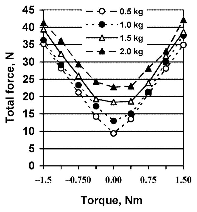
Total normal finger force Ftot as a function of load and torque
The moment arm of the total force D, that is, the distance from the point of application of the resultant force to the center of the thumb transducer, changed sharply when the torque magnitude increased from 0 Nm to 0.375 Nm, but further increases in external torque induced smaller displacements of the point of force application (Fig. 5). The larger external torques (1.125 Nm and 1.5 Nm) were counterbalanced primarily by increases in Ftot, while the moment arm of the resultant force changed only slightly (especially for CW supination torque efforts). Hence, depending on the magnitude of the external torque, subjects used different strategies to counterbalance it. From Figs. 4 and 5, it follows that small torques are controlled mainly by changes in the force-sharing pattern (i.e., the redistribution of forces among the fingers) while large torques are primarily controlled by the magnitude of the total force. Torques of equal magnitudes in the CW and CCW directions induced displacement of the point of force application by similar magnitudes.
Fig. 5.
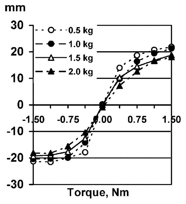
Position of the point of application D (millimeters) of the total finger force for different loads and torques
3.2 Individual finger forces: sharing labor among the fingers
The forces of the ‘peripheral’ (index and little) fingers depended mainly on the external torque to be counterbalanced, while the forces exerted by the ‘central’ (middle and ring) fingers depended on both the external torque and external load (Fig. 6). Hence, the peripheral fingers are the main moment generators.
Fig. 6.

Individual finger forces observed for the different load/torque combinations
When working as an agonist, the index finger exerted a force that was proportional to the pronation moment; this relationship was found to be linear. When a supination moment was required, the index finger was still active and generated an antagonist moment in a pronation direction. Likewise, the ring and little fingers contributed to the supination moment when working as agonists and were not relaxed completely when a pronation moment was required. The middle finger generated larger forces in response to larger external torques almost without regard to the direction of the external torque.
3.3 Individual finger forces: dependence on the mechanical advantage
There was a monotonic relationship between the mechanical advantage of a finger (i.e., its moment arm during torque production) and the force produced by that finger. This relationship, however, was not linear (Fig. 7).
Fig. 7.
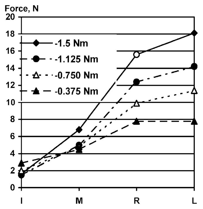
Relationship between finger force and finger position during supination efforts for a 2.0 kg load. The letters I, M, R, and L correspond to the index, middle, ring, and little fingers, respectively. The distance between the fingertip centers of adjacent fingers was 25 mm
3.4 Agonist and antagonist moments
Individual fingers exerted moments of force in the intended direction of the total moment (agonist moments) as well as in the opposite direction (antagonist moments). For instance, in tasks requiring pronation moments, the index and middle fingers were activated. However, the ring and little fingers were not relaxed; they generated force and produced supination (antagonist) moments. The antagonist moments for the various load and torque conditions are presented in Fig. 8. For small torques, the antagonist moments were as high as 40–60% of the agonist moments; for large torques, they were approximately 10–20% of the agonist moments. Hence, some fingers ‘work in the wrong direction.’ Consequently, the fingers that generate agonist moments should exert larger compensatory forces.
Fig. 8.

‘Antagonist/agonist moment’ ratio as a function of torque. Antagonist moments were observed over the entire range of load/torque combinations. The ratios for the zero-torque conditions were estimated from equilibrium requirements under the assumption that the normal forces of the two pairs of fingers were equal
4 Discussion
Figures 2–8 show that there are regularities in the way finger forces are coordinated according to the requirements of the task. The necessity of some of the finger activation patterns, particularly the reason behind antagonist moments, is not clear. The antagonist moments should be counterbalanced by increased force from the agonist fingers. Hence, any antagonist moment increases the total force production. Such a coordination pattern appears to be suboptimal. The first question to consider is: are antagonist moments mechanically necessary?
4.1 Mechanically necessary and mechanically unnecessary antagonist moments
As follows from basic statics, maintaining the handle in an equilibrium position entails that the following requirements should be satisfied: (i) the sum of the normal finger forces is equal in magnitude to the force of the thumb, (ii) the sum of the shear forces exerted by the fingers and thumb is equal to the total weight of the handle and external load, and (iii) the sum of the moments exerted by the fingers is equal to the torque, Mtot + (Moment of the shear forces) = Torque. Also, the sum of the four normal finger forces should be sufficiently large to prevent slipping, Ftot ≥ Fsl.
The individual finger shear forces and the moments produced by these forces have not been measured. However, the contribution of the total moment of the four finger normal forces to the torque is (almost) constant for any load/torque combination, Mtot/Torque =const. (see Fig. 3). We presume that for any load/torque combination the central controller selects a specific value of Mtot; then the controller still has some freedom in selecting a particular combination of finger forces. We computed the magnitude of Mtot from regression equations relating the moment of the normal forces produced by the fingers to the torque caused by the external load (Sect. 3.1). For instance, the moment of the normal finger forces for the load of 2.0 kg and the torque of 1.5 Nm is Mtot = 0.504(Torque) − 0.01 = 0.746 Nm. For such a load/torque combination, the constraints are Mtot = 0.746 Nm and Ftot>Fsl.
When only agonist fingers are active the constraint equations are
| (4a) |
where F1 and F2 are the normal forces exerted by a ‘central’ (middle or ring) finger and a ‘peripheral’ (index or little) finger, respectively. The latter equation can be transformed into
| (4b) |
where Fmom has dimensions of force. Due to the simplicity of the equations, it is convenient to analyze them graphically. The bold line in Fig. 9 corresponds to the equation F1 + F2 = const., while the three thin lines correspond to (4b) for three different values of Fmom. The force/force combinations above the thick line provide a safe grip while combinations below the line will result in the object slipping from the hand. Those force/force combinations that are (a) above the line F1 + F2 = const. and (b) on the line F1 + 3F2 = Fmom satisfy the task requirements.
Fig. 9.
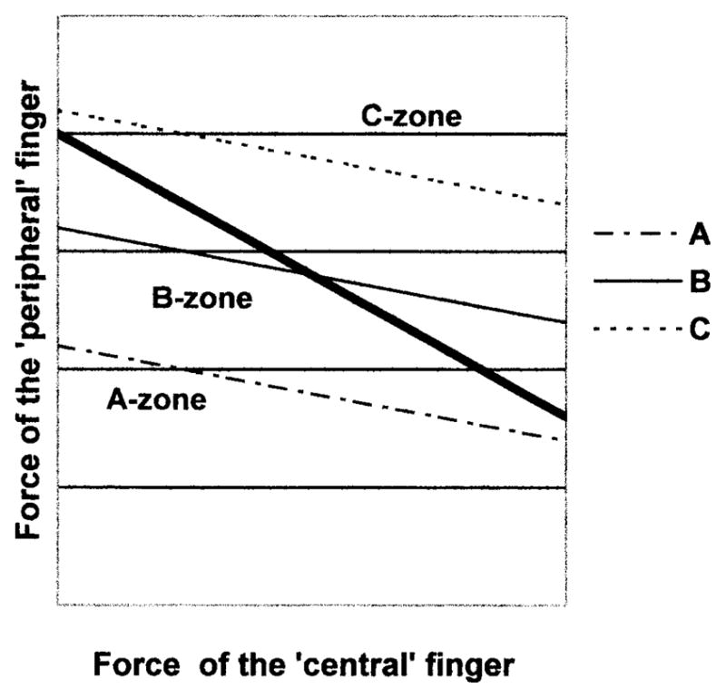
Finger forces at different load/torque combinations (see text for explanation). The thick line represents an equation F1+F2=const. Lines A, B, and C exemplify the force/force combinations that produce moments in the A, B, and C zones, respectively
From Fig. 9, it is evident that three possible load/torque combinations exist (a three-zone model):
Large load/small torque combinations. The line for Fmom is below the line for F1 + F2 = const. over the entire spectrum of force/force values. The only option to prevent slipping is to activate antagonist fingers and, hence, generate an antagonist moment. Such an antagonist moment is mechanically necessary.
Intermediate load/intermediate torque combinations. The line for Fmom is below the line for F1 + F2 = const. in the left part of the graph where the F1 values are small, and it is in the slip-safe range in the right part of the graph where the F1 values are large. To prevent slipping, a performer has two options: either (a) exert larger force with the agonist ‘central’ finger while simultaneously decreasing the force of the agonist ‘peripheral’ finger such that the relationship F1 + 3F2 = Fmom is maintained, or (b) activate the antagonist fingers.
Small load/large torque combination. The line for Fmom is above the line for F1 + F2 = const. over the entire range of force/force values. There is no need for the performer to be concerned about the object slipping from the hand: any force/force combination that satisfies equation F1 + 3F2 = Fmom is sufficient for slip prevention. In this range, antagonist moments are not necessary.
The slip force is Fsl = Fthreshold/μ, where Fthreshold is the minimal shear force that prevents slipping and μ is the coefficient of friction. When the external torque is zero, the shear force of the thumb is equal to approximately one-half of the total supported weight (weight of the handle/beam apparatus plus the external load). During supination efforts the thumb shear force exceeds 50% of the weight, while during pronation efforts the shear force is smaller (see Fig. 2). Hence, the shear force generated by all four fingers is less than 50% of the total weight force during supination efforts and exceeds this value during pronation efforts. In addition, individual fingers may produce forces in different directions; the ratio shear force/normal force may be different for different fingers (Li 2002). Hence, each finger has its own slip force. When the shear force resisted by an individual digit increases, the digit slip force (i.e., the normal force necessary to prevent slipping at the finger–object interface) also increases. For that reason, the slip forces of individual digits depend not only on the supported load but also on the torque. Because we did not register the shear forces produced by the fingers, we are limited in our ability to apply the proposed three-zone model to actual data. Therefore, Fig. 9 should only be regarded as a schematic representation of a general concept. Based on this figure, it is possible to conclude that increasing Fsl (moving the thick line upward) should result in shifting some load/torque combinations from zone B to zone A and from zone C into zones A and B.
4.2 The three-zone model vs. actual data
During ‘large load/small torque’ tasks, antagonist moments are mechanically necessary (zone A). In this zone, slipping cannot be prevented without activation of ‘torque antagonists;’ i.e., fingers that produce antagonist moments. Contrary to this, during ‘small load/large torque’ conditions, activation of antagonist fingers is not necessary; the normal forces of agonist fingers are sufficient for preventing slips (zone C). Nevertheless, antagonist moments were observed in all three zones. This implies that nonmechanical factors have an effect on individual finger forces in such tasks.
4.3 Basic biomechanics of prehension
During torque production, fingers exert both normal and shear forces (Figs. 2 and 3). During pronation efforts, the shear force of the thumb decreased with the external torque and, hence, the shear force of the fingers increased. The opposite was true for supination efforts (Fig. 10). Because decreased shear forces raise the risk of slipping, normal forces must increase to prevent a slip from occurring. In order to maintain equilibrium, the normal forces of the fingers and the thumb must be equal. Therefore, the normal forces of the thumb and fingers always increased or decreased in conjunction with each other. This explains the findings observed during pronation/supination efforts in which the normal forces were large and the force/torque curves were approximately symmetric with respect to the zero torque conditions (Fig. 4).
Fig. 10.
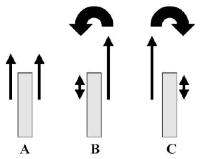
A–C. Schematic of shear forces during torque production. A No torque. The shear forces of the thumb and the fingers are (approximately) equal. B Pronation torque. The shear force of the fingers is larger than the shear force of the thumb. The thumb shear force may be zero or negative. C Supination torque. The shear force of the thumb exceeds the shear force of the fingers. The shear force of the fingers may be zero or negative. The sum of the shear forces equals the total weight of the handheld object in all three cases
The moment produced by the normal finger forces is generated by two mechanisms: (i) changing the sharing pattern and, consequently, the displacement of the point of application of the resultant force; and (ii) increasing the magnitude of the resultant force. The first mechanism dominated for the smaller torques (0.375 N m and 0.75 N m), while for the larger torques (1.125 N m and 1.5 N m) the point of force application did not change substantially and the increase in moment production was achieved by a rise in the force magnitude. In addition, individual fingers were activated according to their mechanical advantage. During pronation/supination efforts, the ‘peripheral’ fingers with the larger moment arms were activated to a larger extent than the ‘central’ fingers with smaller moment arms (Figs. 6 and 7).
On the whole, our results show that coordination of finger forces during static prehension tasks is constrained by both mechanical and neural factors. The regularities in the patterns of digit forces suggest that the neural factor does not simply represent random choice with equal probabilities from a mechanically acceptable set of solutions. Apparently, the CNS uses an additional set of criteria to make such a choice. In Zatsiorsky et al. (2002), we consider different approaches to identifying these criteria based on the current data set and previously published experimental and modeling studies (Zatsiorsky et al. 1998).
Acknowledgments
The authors are grateful to Drs. Boris Prilutsky and Zong-Ming Li for insightful comments on earlier versions of the manuscript. This study was partly supported by NIH grants NS-35032 and AG-18751.
References
- Bernstein NA. On the construction of movements. Medgiz; Moscow: 1947. [Google Scholar]
- Bernstein NA. The co-ordination and regulation of movements. Pergamon Press; Oxford: 1967. [Google Scholar]
- Cutkosky MR, Wright PK. Modeling and manufacturing grips and correlations with the design of robotics hands. Proceedings of the 1986 IEEE International Conference on Robotics and Automation; San Francisco, CA. 1986. pp. 1533–1539. [Google Scholar]
- Goodwin AW, Jenmalm P, Johansson RS. Control of grip force when tilting objects: effect of curvature of grasped surfaces and applied tangential torque. J Neurosci. 1998;18:10724–10734. doi: 10.1523/JNEUROSCI.18-24-10724.1998. [DOI] [PMC free article] [PubMed] [Google Scholar]
- Gregory RW. Biomechanics and Control of Force and Torque Production in Multi-Finger Prehension. The Pennsylvania State University; 2002. Unpublished Ph.D. dissertation. [Google Scholar]
- Johansson RS, Westling G. Roles of glabrous skin receptors and sensorimotor memory in automatic control of precision grip when lifting rougher or more slippery objects. Exp Brain Res. 1984;56:550–564. doi: 10.1007/BF00237997. [DOI] [PubMed] [Google Scholar]
- Johansson RS, Backlin JL, Burstedt MK. Control of grasp stability during pronation and supination movements. Exp Brain Res. 1999;128:20–30. doi: 10.1007/s002210050813. [DOI] [PubMed] [Google Scholar]
- Kinoshita H, Backstrom L, Flanagan JR, Johansson RS. Tangential torque effects on the control of grip forces when holding objects with a precision grip. J Neurophysiol. 1997;78:1619–1630. doi: 10.1152/jn.1997.78.3.1619. [DOI] [PubMed] [Google Scholar]
- Li ZM. Inter-digit coordination and object-digit interaction when holding an object with five digits. Ergonomics. 2002 doi: 10.1080/00140130210129673. (in press) [DOI] [PubMed] [Google Scholar]
- Li ZM, Latash ML, Zatsiorsky VM. Force sharing among fingers as a model of the redundancy problem. Exp Brain Res. 1998;119:276–286. doi: 10.1007/s002210050343. [DOI] [PubMed] [Google Scholar]
- Santello M, Soechting JF. Force synergies for multifingered grasping. Exp Brain Res. 2000;133:457–467. doi: 10.1007/s002210000420. [DOI] [PubMed] [Google Scholar]
- Turvey MT. Coordination. Am Psychol. 1990;45:938–953. doi: 10.1037//0003-066x.45.8.938. [DOI] [PubMed] [Google Scholar]
- Zatsiorsky VM, Li ZM, Latash ML. Coordinated force production in multi-finger tasks: finger interaction and neural network modeling. Biol Cybern. 1998;79:139–150. doi: 10.1007/s004220050466. [DOI] [PubMed] [Google Scholar]
- Zatsiorsky VM, Gregory RW, Latash ML. Force and torque production in static multifingered prehension: biomechanics and control. Control Biol Cybern. 2002;II doi: 10.1007/s00422-002-0321-6. [DOI] [PMC free article] [PubMed] [Google Scholar]