Abstract
Magnetic drug delivery has the potential to target therapy to specific regions in the body, improving efficacy and reducing side effects for treatment of cancer, stroke, infection, and other diseases. Using stationary external magnets, which attract the magnetic drug carriers, this treatment is limited to shallow targets (<5 cm below skin depth using the strongest possible, still safe, practical magnetic fields). We consider dynamic magnetic actuation and present initial results that show it is possible to vary magnets one against the other to focus carriers between them on average. The many remaining tasks for deep targeting in-vivo are then briefly noted.
Keywords: Deep, Focus, Dynamics, Control, Magnetic carriers, Drug delivery, Earnshaw’s theorem, Cancer, Treatment
1. Introduction
In magnetic drug delivery, magnetically responsive objects coated by or containing therapeutic agents are injected into the blood and are then focused to targets in the body by applied magnetic fields. This is useful for treatment of cancer, stroke, infection and other diseases because it allows therapy to be concentrated to disease sites (solid tumors, blood clots, infections) while keeping systemic concentrations low (thus minimizing side effects). The magnetically responsive objects can be micro-or nano-scale iron oxide or other particles coated appropriately to be bio-compatible and therapeutically effective, with sub-micron particles being small enough to pass from the blood to the surrounding tissue through blood vessel walls (with this extra-vasation generally taking place more readily through the leakier blood vessel walls of tumor vasculature). Other objects besides particles, such as polymer, microsphere, micelle, and nano-capsule delivery systems, can also be made magnetic or attached to magnetic particles and then used as magnetic carriers.
A limitation in magnetic drug delivery is the inability to focus treatment to targets deep inside the body. When stationary external magnets are used they attract the particles and can only concentrate them near the skin surface—magnets of a maximum safe strength can only create a <5 cm deep focus [1–3]. This is a well-known and well-recognized problem. It is a fundamental consequence of the classic Samuel Earnshaw 1842 theorem [4]. This theorem states that no inverse-square law force (which includes magnetic forces on a single particle) can create a stable trap in the interior. With a static magnetic field, only unstable equilibria are possible for a ferro- or para-magnetic particle.
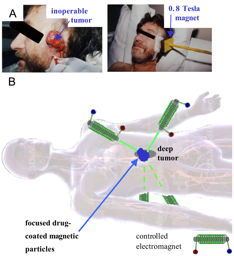
Earnshaw’s theorem can be bypassed in three ways. First, magnets or magnetic materials, such as magnetic stents or magnetizable wires or needles, can be implanted inside the body to create a local magnetic field maximum and attract particles to them [5–11]. Surgically implanting such objects in a patient can be undesirable and is not always possible in a clinical setting. Second, the walls of a container can hold particles away from a magnet: a magnet can trap magnetic carriers against a perpendicular confining wall. But the human blood vasculature network is not a collection of simple, conveniently oriented, confining vessels and, as we see in the animal and human clinical trials of our collaborator [12–14], magnetic carriers spill out from one blood vessel to the next to collect at vessels closest to the external magnet. A final way to bypass the theorem is to change the applied magnetic fields in time, and this is the approach we consider here. We ask: is it possible to dynamically manipulate magnetic fields to focus magnetic carriers to deep targets? (Fig. 1).
Fig. 1.
(A) In the phase I human clinical trials of our collaborator Dr. Andreas Luebbe [12–14], magnetic drug carriers can only be focused to tumors at or near the skin surface. (B) Our long-term goal is to dynamically manipulate magnets, one against the other, to focus magnetic carriers between them to deep tissue targets. (Body image from 3D 4Medical anatomy software.)
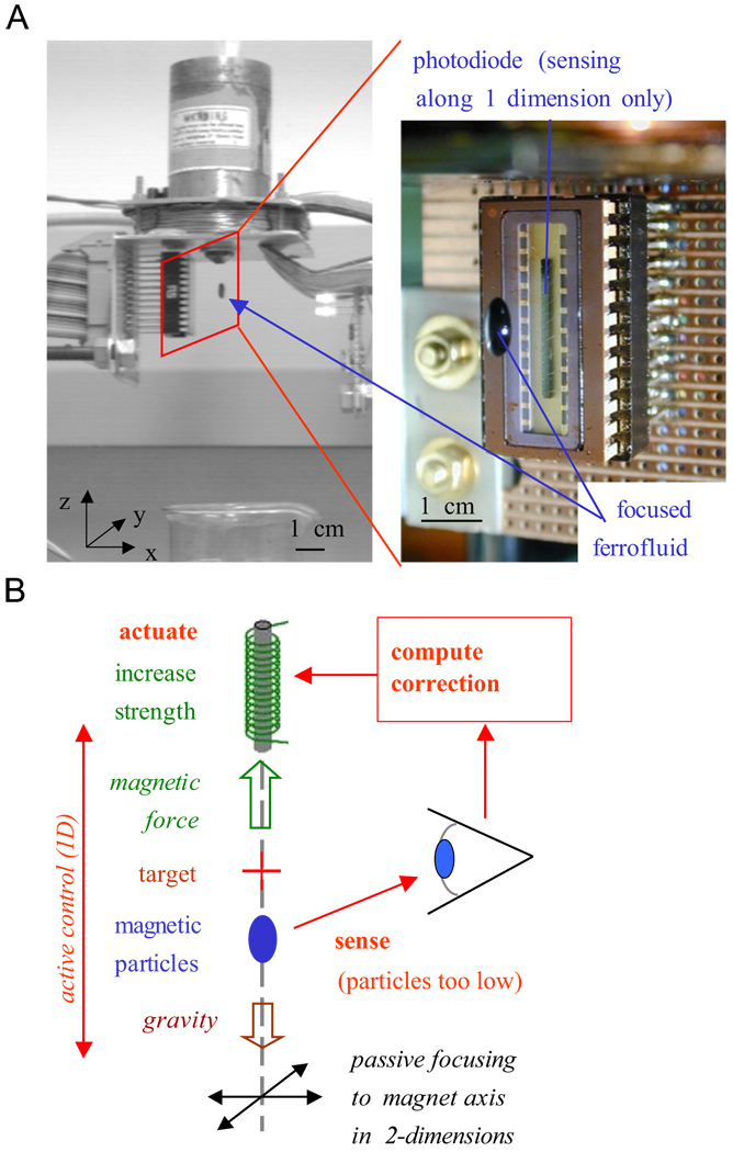
Fig. 2, from the work of Potts et al. [15], shows that dynamic control of just a single electromagnet can bypass Earnshaw’s theorem: it can hold a drop of ferrofluid (nanoparticles in suspension) at a distance from the magnet. Here the drop is held together by surface tension so the control is effectively that of a single object: if the drop is too low it is brought back up and vice versa. Magnetic manipulation of single objects in-vivo by feedback control has been demonstrated by Martel, who has shown steering of one microparticle at a time in swine vasculature using an MRI machine [16,17], and by the company Stereotaxis who precisely controls magnetic fields to help guide surgical tools for magnetically assisted surgery [18]: their instruments have achieved >10,000 successful heart surgeries.
Fig. 2.
Using dynamic actuation it is possible to trap ferrofluid at a distance from a single electromagnet. (A) The controlled magnet applies a field of ~0.02 T and holds a 0.8mm drop of ferrofluid at a 1cm distance. The zoom shows the trapped fluid and the photodiode infrared sensor, which senses the location of the fluid along the z-axis only. (B) Feedback control loop. Focusing in x and y does not require feedback, the particles are passively attracted to the magnet axis. Active control occurs only along z, when the drop is too low the magnet strength is increased to raise it (and vice versa).
During existing magnetic chemotherapy treatment, which has gone through phase I human trials for shallow tumors [13,14] in Germany, the location of advanced and unsuccessfully pretreated cancers or sarcomas is known, a ferrofluid consisting of nano-particles coated with a chemotherapy drug (e.g. mitoxantrone or epirubicin) is injected into a vein, is circulated by the blood flow, and external magnets must then focus it to tumor locations. Thus it is necessary to concentrate a distributed ferrofluid to targets. This is more difficult than magnetically manipulating the location of a single object (as is done in all 3 examples above). Below we investigate whether dynamic magnetic actuation can still bypass Earnshaw’s theorem for a distributed ferrofluid and enable its focusing to deep targets. We present initial control results and note the many steps that remain to move towards deep focusing in a clinical setting. We also briefly discuss real-time ferrofluid sensing as is necessary for feedback control.
2. Modeling
To rationally design dynamic actuation to focus a ferrofluid to deep targets we need a mathematical model of how time-varying actuation will transport the fluid. The model we have developed and implemented here is the simplest one that contains the essential features: dynamic magnetic actuation and the resulting ferrofluid transport.
This model is similar to the one in Grief and Richardson [2] with the difference that we have gone beyond analytical solutions for simple cases and implemented ours numerically (in COMSOL)
| (1) |
| (2) |
Eq. (1), the magneto-static version of Maxwell’s equations is appropriate: our actuation will be quasi-steady compared to radio frequencies. Here B is the magnetic field (in Tesla) with B = μ0(H+M) = μ0(H+χH) where M is the material magnetization, H is the magnetic intensity (A/m), χ is the magnetic susceptibility of the particles (non-dimensional), and j is the current density (A/m2) within the electromagnets.
In the second equation C is the concentration of ferrofluid in the body as a function of time t and space r = (x, y, z). The rate of change of this concentration is given by the gradient ∇ of the flux which has three terms. (1) Convection of particles by the blood flow velocity Vblood. (2) Diffusion of the particles within the blood stream. For spherical nanoparticles in blood at body temperature, Brownian diffusion can be calculated by Einstein’s law, but, as noted by Grief, red blood cell collisions serve to further scatter the particles, and this scattering can be modeled as additional diffusion. (3) Magnetic drift. The applied magnetic field H(r,t) creates an additional velocity of the nanoparticles relative to the blood flow. Its size is determined by the balance between the applied magnetic force and the opposing viscous forces: the coefficient is k = (a2/9η)μ0χ/(1+χ/3) where a is the radius of the particles, η is the viscosity of blood, μ0 = 4π × 10−7 V s/Am is the permittivity of vacuum, and H is the externally appliedmagnetic field intensity. The k coefficient is treated as a constant here even though it can vary due to Stokes drag wall effects (slightly higher drag near blood vessel walls) and potentially due to some amount of particle chaining or aggregation (typically not seen to be significant in Luebbe’s animal and human trials, thus our Eq. (2) does not yet include microscopic agglomeration forces).
As written the model of Eq. (2) is for transport within the vasculature. In surrounding tissue there would be an equivalent partial differential equation but with no blood convection terms and with different (lower) effective diffusion coefficients [19]. Then there would have to be an extravasation term that described ferrofluid transport from blood to surrounding tissue. This level of detail also has not yet been included in our modeling.
This model is currently implemented in 2 spatial dimensions in COMSOL (www.comsol.com) (Fig. 3) via a Matlab script that allows inclusion of feedback control—it allows magnetic actuation to be set by control algorithms that have access to the ferrofluid distribution at each time. The magnetostatic equations are written in vector potential form and the convection–diffusion equation is in conservative weak form and contains a small amount of Petrov–Galerkin streamline diffusion to prevent numerical instabilities. Both are solved simultaneously using 6th order Lagrange-cubic finite elements. The model can handle any time-varying control inputs, pre-planned or due to closed-loop feedback control, but it smoothes out sharp jumps in time, such as suddenly turning on a magnet, over a small interval. Typically, the model has ~3000 mesh points and runs in minutes to a few hours on a personal computer (depending on the complexity of the control algorithm). For the control case below the model is solved in non-dimensional parameters and there is no blood flow velocity yet (Vblood = 0) since our first goal is to determine if we can focus a distributed ferrofluid without any disturbances due to convection.
Fig. 3.
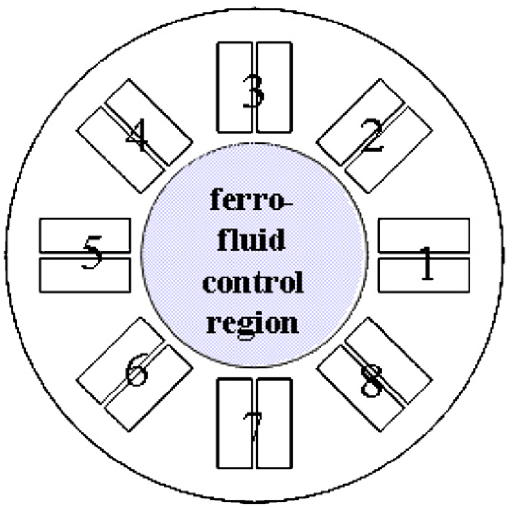
Current model setup. Eq. (1) is solved everywhere in the simulation domain which includes the 8 controlled magnets and the inner domain where ferrofluid transport takes place (Eqs. (1) and (2)).
Non-dimensional parameters for our simulation were set at diffusion D = 1 and magnetic drift coefficient k = 1000 with initial conditions C(x,y,0) = 1. The eight magnets were spaced out equally at a radius of 1.5 (origin to center of each magnet) had a length of 0.8 and a width of 0.35 (0.15 for each half of the coil with a 0.05 gap). The electromagnets were actuated by imposing opposing vertical currents through the two coil halves: in Fig. 4 an inward arrow −1 actuation means that the half-coil in the clockwise direction had a −1 (down) current and the other coil had a +1 (up) current; vice versa for a reversed polarity (outward +1) actuation. For numerical stability, the compensated Petrov–Galerkin streamline diffusion parameter was δSD = 0.5. There are many additional complexities to implementing the model in COMSOL, e.g. numerically handling ferrofluid pileup at domain edges, which cannot be described here due to limited space. Any reader who wishes to replicate the simulation should contact the author for details.
Fig. 4.
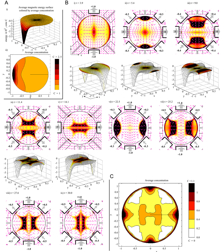
(A) Constant actuation: ferrofluid transport due to turning on the 5th (far left) magnet. (i) The magnetic energy surface U = −kH2 is plotted along the z-axis to show ferrofluid flowing downhill along the force directions F = −∇U with the resulting averaged concentration shown by the coloring here and in sub-panel (ii). (B) Dynamic control: magnets are now turned on and off to transport ferrofluid to the center. The first 5 sub-panels show ferrofluid concentration and magnetic actuation with the corresponding magnetic energy surfaces. Energy surfaces for the last 4 panels (not shown) are 90° flips of the ones shown (see the main text). Coloring denotes concentration (scale bar same as in C). On magnets are illustrated by heavy black lines with weighted thick gray arrows and numbering showing magnet strength and orientation (South to North outwards is a positive polarity). Thin pink arrows (normalized to unit length) show magnetic force directions which match the gradients of the magnetic energy surfaces (forces point down the surfaces). (C) The resulting time-averaged ferrofluid concentration. Note the on-average hot spot at the center target.
3. Magnetic control
Panel A of Fig. 4 first shows the response of the ferrofluid to a single magnet that is turned on and left on. This simulation begins with a uniform ferrofluid concentration at time zero: C(x,y,0) = 1. Fluid moves towards the highest magnetic field amplitude squared (to the maximum of H2) and collects as close to this maximum as possible. If all 8 magnets were turned on and left on, the ferrofluid would collect at 8 spots nearest to the 8 magnets. This would also create a transient hot spot at the center since fluid there would be removed last. Creating such a “focus” by depleting ferrofluid everywhere else is not a viable in-vivo targeting approach since blood flow would quickly wash away this remaining region of the ferrofluid. Instead, our goal is to actively move ferrofluid to the deep target.
Our first dynamic control algorithm is shown in panel B of the figure. At time t = 0 we turn on the y-axis magnets (3rd and 7th) along the same direction (i.e. opposite polarity in the convention of Fig. 4) with unit strength. This creates the highest magnetic field along the y-axis, and along this axis, the field is highest nearest the two on magnets. The resulting magnetic energy surface is a saddle, as shown in panel B(i) bottom. Fluid flows down this saddle: it forms a transient hot spot at the center (where depletion is slowest) and collects near the two on magnets.
The key difficulty now is to get the ferrofluid out from near the two y-axis magnets and moving towards the center. To do so, at time t = 4, we switch the 8 magnets to values u = [+1, +0.3, 0, −0.3, −1, −0.3, 0, +0.3] as shown in panel B(ii). The extra |0.3| values of magnets 2, 4, 6, and 8 create two local unstable (energy maxima) along the y-axis just outside the ferrofluid hot spots (see the force arrow sources in panel B(ii) adjacent to magnets 3 and 7) and they cause the ferrofluid to spill down the energy surface towards the center target.
Ferrofluid continues to move in along the y-axis but by t = 9 there is a significant amount of spreading out along the x-direction, towards magnets 1 and 5. (Looking at the energy surface in panel B(iii) it is visible how the ferrofluid hot spot is on a surface that is curved along the x-direction.) To combat this, we turn magnets 2, 4, 6 and 8 on to higher values (this switch from |0.3| to |0.5| happens smoothly from t = 8.9 till t = 9.1) which flattens out the energy surface in x somewhat (panel B(iv)) limiting further spread in x but continuing to drive the fluid in along y.
By t = 14.1, the ferrofluid hot spot has reached the center target but has nevertheless spread significantly in x. We now turn on the x-axis magnets 1 and 5, at t = 14, to create foci near those magnets. The sequence then repeats in the x-direction: place saddles outside the foci to drive them back in (t = 20) and flatten the energy surface in the y-direction at t = 25 to limit spreading in the y-direction. The results, both in terms of ferrofluid concentration and the energy surface (not shown) are 90° flips of those already shown in the y-direction. As this sequence repeats our control scheme continually drives ferrofluid through the center thus creating a hot spot on average at the central target (as shown in panel C).
This control algorithm was chosen by hand and is far from optimal. We have begun to phrase optimization problems that will optimize each step (shape foci at edges, move to center, prevent spread in other directions, repeat). For example, maximizing fluid transport from a current hot spot to a neighboring target region or way point, the move problem, can be cast as a quadratic optimization program. Instead of choosing values for the side-magnets (2, 4, 6, and 8 above) by hand to flatten out a region, we will be able to choose magnet values optimally. It is also clear how our control schemes can begin to be extended to deal with a disturbing convective flow. Energy surfaces can be shaped and re-oriented to bring the fluid back as it is disturbed. More sophisticated control schemes will correct the location of hot spots and also refocus them. For example, initial optimization results show that it is possible to move and shorten hot spots along their longest axes—by placing energy maxima or saddles behind them to cause the tail end to catch up with the front end. To what degree this is possible, and how best to do it, are still open research questions—especially in the in-vivo context.
3. The in-vivo problem
We recognize that the in-vivo deep target control problem has many more factors than those addressed in our starting simulations and initial control scheme above. Further, we note that the mathematics of the control problem (focusing a distributed fluid to an internal target) is non-standard and difficult—there are no existing control methodologies to do this. Still, focusing of magnetic chemotherapy in humans has been achieved for shallow targets [12–14], our aim now is to create control algorithms that will push that focusing deeper into the body.
Vasculature geometry and blood flow will vary from patient to patient and, with the possible exception of major vessels visualized by MRI, will not be known in a clinical setting. The goal will be to use applied (thus known) magnetic fields to manipulate the ferrofluid and, as unknown blood forces disturb it, to continuously put it back to the deep tumor (feedback control). We believe patient-to-patient vascular geometry variation will not prevent this task in the following sense. Metabolically active cells are within <100 µm of blood vessels [19], so the length scale of vasculature connectivity is generally very small compared to the desired focusing length scale (focusing to a deep target centimeters across would be a dramatic achievement). If there is a concentration of ferrofluid to the right of our target, and we apply a magnetic force to move it left, there should be enough vasculature connectivity to allow the ferrofluid to find a path from right to left. When there is insufficient vasculature connectivity, the control algorithm will see that the fluid is not moving back to its target, and will take corrective actions to circumvent obstructions.
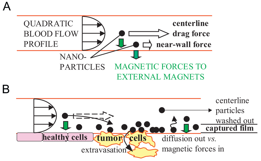
The issue of sufficient magnetic forces versus blood convection forces is subtle. Blood drag flow forces vary with particle position in the blood vessel: a particle at the vessel center-line will see a high velocity and hence high drag force, but a particle near the blood vessel wall will see a near zero velocity (due to the no-slip boundary condition at the wall) and can be held by a small magnetic force (Fig. 5). Trapping of a particle in a blood vessel occurs if the magnetic field pulls the particle out of the strong center-line flow before it leaves the vessel [1,20]. Thus, when nanoparticles are trapped, they are confined in thin films at the inside boundaries of blood vessels, which is exactly where they must be to subsequently be taken up by surrounding tissue. It is these thin films of nanoparticles that we must continuously put back to deep tumor locations by dynamic control.
Fig. 5.
Magnetic and blood drag forces on nanoparticles. (A) The quadratic flow profile in a blood vessel creates large drag forces on particles at the center-line but only small forces on particles near the vessel wall. (B) Nanoparticle capture will occur in a thin film at vessel walls but the thickness of the film will depend on the blood flow velocity and the strength of the magnetic field gradient. (In small capillaries the blood flow profile shape is more blunted. In blood-cell diameter micro-capillaries where red blood cells pass through in single file, a blood flow “velocity profile” is not defined.)
Initial calculations show that, using MRI-strength magnets, there should be sufficient force to actuate nanoparticles, even at 20–30cm depths. In humans, blood flow velocities range from >1 m/s highest peak velocity in the ascending aorta to ~30 cm/s in main blood return arteries to <5 mm/s in arterioles and venules [1,2,19,21]. Magnetic forces will not capture particles against the high flow rates in major arteries, instead, focusing will have to be carried out by thin films moving along secondary blood vessels (as does happen in animals and humans for successful focusing to shallow targets). Computing the distance from the vessel wall in a quadratic flow profile where blood drag flow forces can first overcome the applied magnetic force and wash away the particles, for a 4T magnet and accounting for particle magnetic saturation, a ferrofluid film of a micrometer to a few hundred nanometer thickness should form in capillaries 20 to 30 cm deep. Particle chaining and agglomeration, to the degree that they may occur in-vivo, may also increase forces by allowing magnetic forces to act on particles in small groups.
Deep in-vivo real-time ferrofluid sensing for feedback control can be achieved by making the particles slightly radioactive, as is done in [22], so that their position can be detected by next-generation gamma cameras. The radiation dose absorbed by the body during such nuclear imaging is small, far less than an X-ray. CMOS gamma cameras for high-speed imaging are being developed by Westbrook [23,24]. These cameras function at >10 kHz (far in excess of the speeds we need to combat the ~1Hz heart-rate blood-flow disturbances in humans), their pixels can be tilted and tiled without gaps, and can be batch fabricated at reasonable cost. It will be possible to coat the inside of a sphere or tube with these pixels to form a gamma ‘camera’ that would have near complete solid angle viewing (except for obstructions). Initial calculation shows that such cameras will be able to detect magnetic nanoparticles at the concentrations used during Luebbe’s human trials. Or, as pointed out by Martel, magnetic fields can be duty cycled to both actuate (control mode) and sense (MRI mode) but this leads to a loss in control effectiveness since part of each cycle is devoted to sensing.
4. Conclusion
Unless magnets or magnetic materials are surgically implanted in patients, which is undesirable and often not clinically feasible, magnetic drug delivery is limited to shallow targets (typically <5 cm depth with the strongest possible, still safe, magnetic fields).We consider dynamic control of magnets to focus magnetic carriers to deep tissue targets. Based on a first-principles magneto-statics and ferrofluid transport model we show that a sequence of actuations can drive ferrofluid always through a center region thus creating a focus at this deep target on average. Many issues remain to move this control from our initial demonstration (in 2 spatial dimensions, without a vasculature network, with no disturbing blood flow forces yet) closer towards clinical use. Next steps include: optimizing the control actions; taking the modeling and control from 2 spatial dimensions to 3; incorporating a vasculature geometry and the strong disturbing actions of blood flow and accounting for them in the control; then, demonstrating the methods experimentally in a laboratory setting; enabling real-time ferrofluid sensing for in-vivo feedback control; and moving to animal and then human experiments similar to the ones our collaborator Luebbe has done for magnetic drug delivery to shallow tumors.
Acknowledgements
The author would like to thank Andreas Luebbe for his long-standing collaboration on this project, Roland Probst for his help in a literature and patent search, Hugh Potts and Declan Diver for their collaboration and permission to use Fig. 2A, Ed Westbrook for discussions on gamma cameras, and finally, COMSOL and Nils Malm and Jeanette Littmarck at COMSOL for providing programming support for the COMSOL/Matlab simulations in Section 2. The author is a member of the Institute of Systems Research and the University of Maryland Nano Center.
References
- 1.Voltairas PA, Fotiadis DI, Michalis LK. J. Biomech. 2002;35:813. doi: 10.1016/s0021-9290(02)00034-9. [DOI] [PubMed] [Google Scholar]
- 2.Grief AD, Richardson G. J. Magn. Magn. Mater. 2005;293:455. [Google Scholar]
- 3.Häfeli UO, Gilmour K, Zhou A, et al. J. Magn. Magn. Mater. 2006 [Google Scholar]
- 4.Earnshaw S. Trans. Cambridge Philos. Soc. 1842;7:97. [Google Scholar]
- 5.Iacob G, Rotariu O, Chiriac H. J. Optoelectron. Adv. Mater. 2004;6:713. [Google Scholar]
- 6.Ritter JA, Daniel KD, Ebner AD. Abstr. Pap. Am. Chem. Soc. 2003;225:U991. [Google Scholar]
- 7.Iacoba GH, Rotariub O, Strachan NJ, et al. Biorheology. 2004;41:599. [PubMed] [Google Scholar]
- 8.Aviles MO, Ebner AD, Chen HT, et al. J. Magn. Magn. Mater. 2005;293:605. [Google Scholar]
- 9.Rosengart AJ, Kaminski MD, Chen HT, et al. J. Magn. Magn. Mater. 2005;293:633. [Google Scholar]
- 10.Rotariu O, Strachan NJC. J. Magn. Magn. Mater. 2005;293:639. [Google Scholar]
- 11.Yellen BB, Forbes ZG, Halverson DS, et al. J. Magn. Magn. Mater. 2005;293:647. [Google Scholar]
- 12.Lubbe AS, Bergemann C, Huhnt W, et al. Cancer Res. 1996;56:4694. [PubMed] [Google Scholar]
- 13.Lubbe AS, Bergemann C, Riess H, et al. Cancer Res. 1996;56:4686. [PubMed] [Google Scholar]
- 14.Lemke AJ, von Pilsach MIS, Lubbe A, et al. Eur. Radiol. 2004;14:1949. doi: 10.1007/s00330-004-2445-7. [DOI] [PubMed] [Google Scholar]
- 15.Potts HE, Barrett RK, Diver DA. J. Phys. D—Appl. Phys. 2001;34:2629. [Google Scholar]
- 16.Martel S, Mathieu J-B, Felfoul O, et al. Appl. Phys. Lett. 2007;90:114105. [Google Scholar]
- 17.Mathieu JB, Martel S. Biomed. Microdev. 2007;9 doi: 10.1007/s10544-007-9092-0. [DOI] [PubMed] [Google Scholar]
- 18.Ritter RC. Patent No. 6,241,671, USA
- 19.Saltzman WM. Drug Delivery: Engineering Principles for Drug Therapy. New York: Oxford University Press; 2001. [Google Scholar]
- 20.Mikkelsen CI. Magnetic Separation and Hydrodynamic Interaction in Microfluidic System. Denmark: Thesis, Technical University of Denmark, Lyngby; 2005. [Google Scholar]
- 21.Ganguly R, Gaind AP, Sen S, et al. J. Magn. Magn. Mater. 2005;289:331. [Google Scholar]
- 22.Kim C-O, Kim J-H, Huang Y-Q, et al. Radioactive Magnetic Fluids for Treatment or Diagnosis of Cancer, Process for Preparing Them and Use. 2009 US patent application number 20050019257.
- 23.Parker SI, Kenney CJ, Gnani D, et al. IEEE Trans. Nucl. Sci. 2006;53:1676. [Google Scholar]
- 24.Kenney CJ, Segal JD, Westbrook EM, et al. Nucl. Instrum. Methods Phys. Res. A. 2006;565:272. doi: 10.1016/j.nima.2006.05.012. [DOI] [PMC free article] [PubMed] [Google Scholar]


