Abstract
We describe the first mapping of biological current in a live heart using ultrasound current source density imaging (UCSDI). Ablation procedures that treat severe heart arrhythmias require detailed maps of the cardiac activation wave. The conventional procedure is time-consuming and limited by its poor spatial resolution (5–10 mm). UCSDI can potentially improve on existing mapping procedures. It is based on a pressure-induced change in resistivity known as the acousto-electric (AE) effect, which is spatially confined to the ultrasound focus.
Data from 2 experiments are presented. A 540 kHz ultrasonic transducer (f/# = 1, focal length = 90 mm, pulse repetition frequency = 1600 Hz) was scanned over an isolated rabbit heart perfused with an excitation-contraction decoupler to reduce motion significantly while retaining electric function. Tungsten electrodes inserted in the left ventricle recorded simultaneously the AE signal and the low-frequency electrocardiogram (ECG). UCSDI displayed spatial and temporal patterns consistent with the spreading activation wave. The propagation velocity estimated from UCSDI was 0.25 ± 0.05 mm/ms, comparable to the values obtained with the ECG signals. The maximum AE signal-to-noise ratio after filtering was 18 dB, with an equivalent detection threshold of 0.1 mA/cm2. This study demonstrates that UCSDI is a potentially powerful technique for mapping current flow and biopotentials in the heart.
I. Introduction
A. Motivation and Background
Many cardiac arrhythmias and other cardiac disorders are intractable with drug therapy and require an interventional procedure, which may include ablation or implantation of pacemakers. Tens of thousands such procedures are performed in the United States each year [1]. They typically require a detailed map of the electrical activation wave before ablation therapy.
The conventional mapping procedure uses electrode catheters in contact with the endocardial wall and is guided by fluoroscopy and electroanatomical mapping. This is a slow procedure with poor spatial resolution (5–10 mm) [2], [3]. The duration of the procedure can be reduced with noncontact mapping using a free-floating electrode catheter array. With noncontact mapping, the endocardial potential distribution is estimated from the voltage measured at the catheter by solving an inverse problem. This inverse problem is ill posed and sensitive to electronic noise [4]. There are also errors due to geometrical estimation of the endocardial surface. The electroanatomical map is typically coarse and is sometimes improved by registering it to a static image obtained with computed tomography (CT) or magnetic resonance (MR) images. These images are captured preoperatively, and the registration error between them and the electroanatomical map can be as great as 10 mm [5], [6].
We have previously developed a method to image electric current flow in biological tissue called ultrasound current source density imaging (UCSDI). In this paper we describe the first measurements of biological current in live rabbit hearts using UCSDI. A preliminary report of this work has been given elsewhere [7]. Although this paper emphasizes UCSDI for cardiac procedures, it is clear that UCSDI could also help map currents in the brain, such as imaging an epileptic foci [8].
UCSDI is based on the acousto-electric (AE) effect, a resistivity modulation induced by ultrasonic pressure, and can be described by
| (1) |
where Δρ is the resistivity change, ρ0 the direct current (DC) resistivity, ΔP the acoustic pressure, and KI a constant of interaction whose value is on the order of 10−9 Pa−1 in a 0.9% NaCl solution [9]–[11].
We have previously tested UCSDI by mapping artificially generated current patterns in phantoms and excised tissue, demonstrating that UCSDI was sensitive enough to detect biological currents [8], [12], [13]. We have also shown how to reconstruct current densities with UCSDI [14], [15]. Another group has shown that AE imaging can be used to map conductivity distributions [16].
B. Acousto-Electric Signal Generation and Measurement
We have previously shown in [14] that in AE measurements the voltage Vn-m between 2 electrodes, n and m, is the sum of 2 signals
| (2) |
where is the normal low-frequency (DC-10 kHz) biopotential signal and is the high-frequency (MHz) ultrasound modulated AE signal. We can write as
| (3) |
where is the lead vector field of the electrode pair n-m, and J I = J I(x, y, z, tslow) is the propagating biological current source, and the dot between and JI indicates a dot product. The macroscopic current density of the cardiac activation wave can be modeled as the gradient of the membrane voltage with the following equation:
| (4) |
where Vm(t) is the cellular membrane voltage, Δ is the gradient operator, and σi is the local intracellular conductivity [17]. Note that Vm(t) satisfies the wave equation due to the regenerative properties of excitable membranes. The rise time of Vm(t) is approximately 1 ms. Assuming a propagation velocity of 0.1 to 1 mm/ms, in an infinite medium (4) describes a sheet of dipoles approximately 0.1 to 1 mm thick. For simplicity, we analyze results using 2 time variables, slow-time (tslow) and fast-time (tfast). Fast-time is the time frame of propagating ultrasound (μs), whereas slow-time is the time frame of biological current activity (ms). The lead field of the electrode pair is its integration volume or sensitivity distribution. It has units of per square meter, and it has the same shape as the electric field produced when a unit current is injected through the electrodes [17].
The AE signal equation, describing , was derived in [14]. For a transducer positioned at point (x1,y1), the AE signal is given by (5) (see above), where b(x,y,z) the beam pattern of the transducer, P0 the acoustic pressure amplitude, a(t) the acoustic pressure waveform, and c the speed of sound. The difference between (5) and (3) is the introduction of the ultrasound system as a spatio-temporal filter. As a consequence, the AE signal, , depends on the value of JI only within the focal zone of the beam, localizing the electrical measurement. The high-frequency content of the acoustic pulse a(t) is a spatial label of , which can be extracted easily from Vn-m.
| (5) |
Mapping cardiac activation waves using UCSDI has several potential advantages. The resolution is determined by the typicall sub-millimeter resolution of the acoustic pulse, and acoustic beam mapping can be accomplished rapidly with electronic beam steering. Because the same acoustic pulse generates both and the normal B-mode ultrasound image, UCSDI is automatically registered to the conventional ultrasound image. In the remainder of this paper, we conclusively show that UCSDI also has the sensitivity required to image biological currents.
II. Methods
A. Langendorff Isolated Rabbit Heart Setup
Two hearts were excised from white New Zealand rabbits. They were used in separate experiments and will be referred to as hearts A and B. Each was placed in a Langendorff setup and retroperfused through the aorta with a modified Kreps-Henseleit (K-H) buffer (NaCl, 117 mM; KCl, 4 mM; MgCl2, 1.2 mM; KH2PO4, 1.1 mM; glucose, 5 mM; NaHCO3, 25 mM; and CaCl2, 2.6 mM; pH 7.44, 37°C) oxygenated with a mixture of 95% O2 and 5% CO2 [18]. To eliminate motion artifacts, 15 mM of an excitation-contraction decoupler (2,3-butane dione monoxime; BDM) were mixed into the K-H buffer. BDM reduces mechanical contraction, yet preserves the electrical cardiac wave [19]. All protocols were approved by the University Committee on the Use and Care of Animals at the University of Michigan.
B. Instrumentation
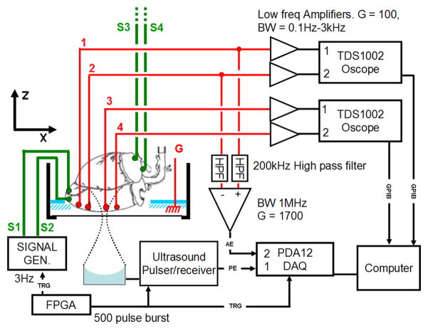
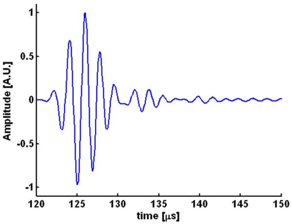
The experimental geometry is shown in Fig. 1. Each heart was placed in a small tank inside a larger outer tank. The outer tank was filled with deionized water and a single element 540-kHz f/1 ultrasound transducer with 90 mm focal length (Etalon, Indianapolis, IN) and a fractional bandwidth of 39% was placed in the water underneath the small tank. The heart was placed in a custom-made holder in the inner tank such that the long axis of the heart was horizontal and the left ventricle facing down. In Fig. 1, the long axis of the heart coincides with the x-axis of the imaging coordinate system. Fig. 2 shows a pulse-echo of a flat air/water interface capturing the impulse response of the ultrasound transducer used for these studies. The amplitude at the focus was approximately 2 MPa as estimated using a fiber optic hydrophone.
Fig. 1.
Experimental setup. Four tungsten-stimulating electrodes (S1, S2, S3, and S4) and 4 recording electrodes (1, 2, 3, and 4) were inserted into the heart. S1 and S2 were inserted into the apex and S3 and S4 were inserted into the right atrium. The recording electrodes were inserted in a line parallel to the long axis of the heart. The voltage on each electrode with respect to ground (G) was amplified with a low-frequency amplifier and digitized with an oscilloscope (TDS 1002). In addition, 2 of the recording electrodes (here electrodes 1 and 2) were connected via an analog high-pass filter to a differential amplifier. The high-frequency voltage (AE) was sampled and digitized concurrently with the pulse-echo (PE) signal by a digital acquisition board (DAQ). A field-programmablegate-array (FPGA) controlled the experimental timing. It sent a trigger to the signal generator that paced the heart as well as the ultrasound pulser-receiver. The heart was paced from the apex when the signal generator was connected to electrodes S1 and S2. If the signal generator was connected to electrodes S3 and S4, the heart was paced from the right atrium.
Fig. 2.
Pulse-echo recording by the 540 kHz transducer of the reflected signal from a flat air/water interface. The amplitude of the acoustic pulse measured with a hydrophone was 2 MPa.
Eight Teflon-coated tungsten electrodes were inserted into the heart, 4 recording electrodes (1, 2, 3, 4) and 4 stimulating electrodes (S1, S2, S3, S4). The tip of each electrode was stripped and bent into a hook such that the electrode, once inserted, would have better purchase. One pair of stimulating electrodes (S1, S2) was inserted 1 mm apart into the apex of the heart, while the other pair (S3, S4) was inserted 2 mm apart into the right atrium. The recording electrodes were inserted into the left ventricle in a row approximately parallel to the long axis of the heart. The electrodes were placed sequentially such that 1 was closest to the apex of the heart, while 4 was closest to the base of the heart. The spacing between electrode pairs 1–2, 2–3, and 3–4 was 4, 6, and 3 mm in heart A and 3, 4, and 3 mm in heart B as measured at the conclusion of the experiment. A large ground electrode was placed beside the heart in the small tank.
The pacing signal was a 5 V high and 500 μs wide rectangular pulse emitted by a function generator (33120, Agilent, Santa Clara, CA). The heart was paced either from the apex (with electrodes S1 and S2) or from the right atrium (with electrodes S3 and S4).
Each recording electrode was connected to a low-frequency amplifier with a gain of 100 and bandwidth 0.1 Hz to 3000 Hz. Each amplifier measured the voltage between the corresponding electrode and the ground electrode. Electrodes 1 and 2 were connected to an AM502 differential amplifier (Tektronix, Beaverton, OR), while electrodes 3 and 4 were connected to an SRS560 differential amplifier (Stanford Research Systems, Sunnyvale, CA). These amplifiers recorded the normal low-frequency electrocardiograms (ECG) corresponding to in (3), and their outputs were connected to 2 digital oscilloscopes (TDS1002; Tektronix). The oscilloscopes digitized the signals and sent them via general-purpose-interface-bus (GPIB) to the computer. The sync output of the stimulus function generator was used to trigger data acquisition.
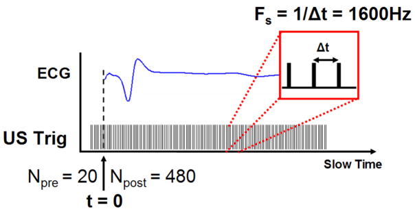
To measure the high-frequency AE signal [corresponding to in (5)], 2 electrodes were connected via an analog high-pass filter (200 kHz, −3 dB frequency) to a differential amplifier (DA1855A; LeCroy, Chestnut Ridge, NY) with a gain of 10 and 1 MHz bandwidth. The AE signal was measured with a pair of electrodes, either 1–2, 2–3, or 3–4. In each case, the electrode with the lower number was connected to the positive terminal of the amplifier. The AE signal was further amplified by 45 dB (5072; Panametrics, Waltham, MA) and low-pass-filtered at 2 MHz (BLP-1.9; Mini-Circuits, Brooklyn, NY). The experimental timing (illustrated in Fig. 3) was controlled by a field-programmablegate-array (FPGA) chip (ezFP-GA; Dallas Logic, Plano, TX). The FPGA sent out 2 trigger signals: a 3 Hz signal to pace the heart and a 500 trigger burst to an ultrasound pulser/receiver (5077PR; Panametrics). Each burst was sent to coincide with the pacing signal such that 20 triggers were sent before the heart was paced and 480 afterwards in one heart cycle. The interval between ultrasound triggers was 625 μs. Consequently, the slow-time sampling rate was 1600 Hz.
Fig. 3.
Experimental timing. The heart was paced by the FPGA at a 3 Hz rate. Prior to the heart stimulus, the ultrasound (US) transducer was given 20 pre-triggers (Npre). After the stimulus, the ultrasound transducer was triggered (US Trig) 480 times at a pulse repetition frequency of 1600 Hz.
The pulser-receiver excited the ultrasound transducer, which was focused on the left ventricle. For each trigger, AE and pulse echo (PE) traces were acquired concurrently and sampled at 12.5 MHz (fast-time sampling rate) by a digital acquisition (DAQ) board (PDA12; Signatec, Newport Beach, CA). Each trace contained 2048 samples. Consequently, data acquired with each trigger burst were two, 2048 × 500 matrices, an AE matrix, and a PE matrix. The first dimension of each data matrix will be hereafter referred to as the fast-time axis and the second dimension will be referred to as the slow-time axis.
C. Experimental Procedure
The AE and PE data were acquired in an XZ-slice by moving the transducer in twenty, 1 mm steps along a line parallel to the x-axis. At each step, AE and PE matrices were averaged over 64 heart cycles (trigger bursts). For each pair of electrodes (1–2, 2–3, 3–4), an XZ-slice was captured for each pacing location, right atrium or apex. After every XZ-slice was captured, 2 control experiments were performed. One (“FOAM”) repeated the experiment unchanged except the path of the ultrasound was blocked with a piece of polystyrene. In the other control (“US off”), the ultrasound path was unobstructed, but the ultrasound transducer was disconnected from the pulser. In the control experiment, only the A-line corresponding to x = 0.54 mm was captured. An XZ-slice corresponding to a single slow-time index will be referred to as a frame in the remainder of the paper.
D. Data Processing
To reduce noise, each data matrix (AE or PE) was band-pass-filtered along its fast-time axis (0.4–0.8 MHz), and AE data were further band-pass-filtered in slow time (pass band = 15 to 80 Hz). The AE signals were converted to complex analytical form, basebanded, and low-pass-filtered in the XZ-plane, where z is the fast time axis. The 2-D filter was Gaussian in the frequency domain with a full width at half maximum (FWHM) = 0.36 mm−1. For fair comparison, low-frequency ECG data were filtered with the same slow-time filter as AE signals.
To gauge the imaging capabilities of the AE measurement system, we calculated the point-spread function (PSF) to estimate the spatial resolution for imaging the cardiac activation wave. The FWHM of the transducer PSF measured with a hydrophone was 5.2 mm axially and 4.1 mm laterally [20]. The FWHM of the PSF of the bandpass filter along the ultrasound propagation axis was 3.87 mm, and the FWHM of the PSF of the 2-D filter was 2.45 mm. The total FWHM of the final image PSF is a convolution of these PSFs. Assuming that the PSFs have Gaussian envelopes, the FWHMs of the image PSF were estimated to be mm axially and mm laterally.
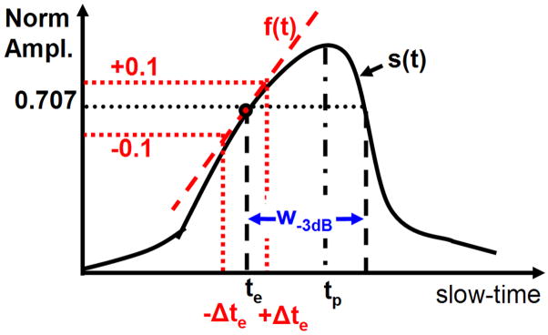
Several parameters derived from ECG and AE signal envelopes were compared: onset latency (te), time-to peak-signal (tp), and the −3 dB width of the signal envelope (w−3 dB). These measurements are illustrated in Fig. 4. The signal-to-noise ratio (SNR) of the AE signal was also measured for each data set. The envelope of the AE signal was found by choosing the peak magnitude of each frame as representative of the AE signal at that slow-time index. The envelope of the ECG signal was similarly obtained by finding the analytic signal along the slow-time axis.
Fig. 4.
Diagram to illustrate measurement of onset latency (te), peak time (tp), and width of the peak at −3 dB (w−3 dB). The solid black line is a normalized signal envelope s(t) in slow-time. The onset latency corresponded to the first time the envelope crossed s(t) = 0.707 (−3 dB). The uncertainty in te, Δte, was estimated by fitting a line f(t) through (te, s(te)) and finding the Δte such that f(te ± Δte) = s(te) ± 0.1. The width w−3 dB was defined as the first and last time the AE signal passed through s(t) = 0.707.
The ECG signal was normalized by subtracting the minimum envelope and dividing by the peak signal, and the AE signal envelope was normalized by subtracting minimum envelope magnitude and dividing the result with the peak envelope. The normalized envelopes of AE and ECG signals were otherwise treated the same.
Although the ECG signals were acquired on all electrodes in each acquisition, the AE signals were acquired on only one pair at a time. As a result of the finite time to complete each AE acquisition and because physiological signals are not strictly deterministic, there were slight differences in timing between each AE acquisition, which were reflected equally in ECG and AE signals. To calibrate, the time to peak of the ECG signal on electrodes 1–2 for each acquisition was measured. Any interacquisition delay was corrected by shifting all ECG and AE signals by the measured delay.
The onset latency (te) was defined as the delay between the stimulation (t = 0) and the time when the envelope first crossed 0.707 (−3 dB point). The −3 dB point was chosen instead of 0.5 because there were some AE signals with poor SNR where that point would not have been meaningful. The uncertainty of te, Δte, was estimated by fitting a line along the envelope at te and finding how much te varied with a 10% change in the envelope magnitude. The time-to-peak signal (tp) was the time between the stimulation and peak envelope, and the −3 dB width (w−3 dB) was the time between the first and last time the envelope crossed the 0.707. The AE-SNR was measured as the ratio of the peak AE signal and the baseline AE signal, in decibels. The baseline AE signal was the root mean square (RMS) value of the AE data matrix corresponding to the 20 pre-stimulus triggers.
E. Displacement Estimation
Correlation-based phase-sensitive 2-D speckle tracking [21] was used to estimate residual motion using XZ-plane PE images. The tracking algorithm calculated the complex cross-correlation coefficient between speckle-sized blocks in a reference frame and every other frame. Correlation coefficient functions were filtered to reduce tracking error. Axial and lateral dimensions of the correlation kernel were estimated from the FWHM of the magnitude of the autocorrelation function to be 3.1 mm × 5 mm (52 × 5 samples), and the correlation filter was chosen as 7.8 mm × 7 mm (130 × 7 samples).
Coarse estimates of both axial and lateral displacements were computed by finding the peak position of the magnitude of the correlation coefficient function using a parabolic fit. The axial displacement was further refined by calculating the position of the phase zero-crossing around the peak correlation coefficient [21]. The spatial resolution of the displacement estimate was 8.4 mm × 7.4 mm. Due to the small displacement being estimated and the relatively large variance in lateral speckle tracking, only axial tracking results are presented [22].
The choice of reference frame was derived from low-frequency ECG data. The differential signal between the 3 pairs of electrodes (1–2, 2–3, and 3–4) was calculated. The slow-time segment corresponding to the peak of each differential signal (peak-time) was found. The mean peak time of the 3 differential signals was used as the reference time.
III. Results
We report for the first time mapping of biological current in the live rabbit heart using ultrasound. Three UCS-DI movies (2 from heart A and 1 from heart B) are associated with this paper: A_EL1_2_AT ( ), A_EL1_2_AP (
 ), and B_EL1_2_AP (
 ). The first letter indicates the heart, EL1_2 means that the AE data were measured with electrodes 1–2, and the final 2 letters indicate the pacing location (AT = right atrium, AP = apex). A screen shot from A_EL1_2_AT is presented in Fig. 5 and explained below. Figs. 5–7 correspond to heart A.
Fig. 5.
Example RF-traces. Left: A screen shot from the movie A_EL1_2_AT, representing data from heart A measured with electrodes 1–2 and paced at the atrium. The bipolar acousto-electric (AE) image is superimposed on top of the B-mode pulse-echo image (dynamic range = 30 dB) shown in grayscale. The magnitude of the AE image is logarithmically compressed while keeping the sign of its real part. The white horizontal dotted line is the image line used in the bipolar M-mode displays in Figs. 6 and 7. Right top: Radio frequency (RF) traces corresponding to the dotted white vertical line (x = 0.5 mm) in the figure on the left. The blue solid line is the AE RF trace, the black dashed line corresponds to the control where the ultrasound path is blocked with polystyrene. The red dotted line corresponds to the control where the ultrasound transducer was disconnected from the ultrasound pulser. Right bottom: The PE RF trace acquired concurrently at the same A-line. The black dashed horizontal line marks the interior of the heart. Colors mentioned in the caption refer to the online version of this figure.
Fig. 7.

Right: An illustration of the heart showing the disposition of the recording electrodes (numbered red dots) and the stimulation electrode (green diamond) along the x-axis. Left: The top 2 images are UCSDI bipolar M-mode plots corresponding to the lateral line z = 100 mm. The image at the top was measured on electrodes 1 and 2 while the image below it was measured with electrodes 2 and 3. In the plot second to bottom are low frequency ECG plots measured concurrently on the same electrodes. The solid blue line was measured with electrodes 1 and 2 while the green dashed line was measured with electrodes 2 and 3. At the bottom are the tracking results corresponding to x = 0.54 mm in the top M-mode image. The vertical dashed line in all of the images marks t = 0. The slanted dashed white line in the second row was used to estimate the velocity of the activation wave.
Fig. 5 demonstrates the ultrasound dependence of the AE signal. A single frame from A_EL1_2_AT corresponding to slow-time = 170 ms is shown in Fig. 5 on the left. Each frame is a B-mode pulse echo image (30 dB dynamic range, grayscale) superimposed on which are UCSD images of current flow (hot/cold scale). UCSD images are bipolar (signed), but the amplitude is logarithmically compressed such that positive and negative values have 10 dB of dynamic range. The boundary of the heart in the pulse-echo image is depicted by the dashed white lines, and the location of the acoustic window of the chamber is noted with a white arrow.
Radio frequency (RF) traces shown on the right correspond to the vertical dotted white line in the image on the left. In the plot at the bottom right is the PE RF-trace and a black dashed line that marks the interior of the heart. The RF-traces in the top right were measured with the electrodes where the solid blue line is the AE signal, the black dashed line corresponds to a control where the acoustic path was blocked by a block of polystyrene, and the red dotted line denotes the control where the ultrasound transducer was disconnected. In these plots as well as the image to the left, the fast-time axis (z-axis) has been converted to spatial dimension. The z-axis of the AE plots was converted based on one-way propagation, while the z-axis of the PE plots was converted based on 2-way propagation. The peak amplitude of the blue curve is 0.71 μV, while the RMS values of the black dashed and red dotted curves are 0.09 and 0.15 μV, respectively. If we assume that the controls are a good estimate of the noise, the maximum SNR is 18 and 14 dB after filtering, respectively.
Figs. 6 and 7 show that the AE signal has spatial and temporal patterns consistent with the spreading cardiac activation wave. On the right, Fig. 6 shows both the layout of the recording electrodes with respect to the x-axis as well as the location of the stimulation electrodes on the heart. On the left are results, where each column represents a pair of electrodes 1–2, 2–3, or 3–4. The bottom row presents the low-frequency ECG traces while the images in the top row are bipolar AE M-mode images measured with the same pair of electrodes in which the magnitude of the AE signal is logarithmically compressed and then given the sign of the real part. The magnitude is symmetrically clipped just above the noise level. The time scale is short (0.1–0.2 s) to highlight the disposition of AE signals along x-axis. That is, the signal measured with electrodes 1 and 2 is around x = 0 mm, while the signal measured with electrodes 3–4 is at x = 7 mm. The signal measured with electrodes 2 and 3 is between them.
Fig. 6.
Top row on the left: Lateral bipolar M-mode UCSD images corresponding to z = 100 mm in Fig. 5 where each column is the signal measured by a different electrode pair. In these images, the magnitude of the AE signal is logarithmically compressed and given the sign of the real part. Bottom row: Low-frequency ECG signal measured on the same pair of electrodes as the M-mode plot above. The figure on the right illustrates the geometric arrangement of the recording electrodes (numbered red dots) and stimulation location (green diamond) in the heart with respect to the x-axis. Note that AE signals occur at roughly the same time as the low-frequency signal, yet they are spatially separated along the x-axis.
The small dispersion of signals in slow-time is related to the propagation path of the electrical stimulation. When the heart is stimulated from the atrium, the activation signal travels along the natural pathways throughout the ventricle, and the activation wave travels both from the apex to base as well as transmurally [23]. The long delay from the stimulation to the peak of the signals (0.15 s) is due to propagation delays in the atrium as well as in the atrio-ventricular node [17].
Fig. 7 shows that the AE signal propagated in slow-time and demonstrates the lack of motion during the generation of the AE signal. The geometry of the heart and the disposition of the electrodes are shown on the right. Note that the heart was stimulated at the apex; as a result, the delay between stimulation and the appearance of electrical signals was less than that when the heart was stimulated at the right atrium, as depicted in Fig. 6. The top 2 images on the left are bipolar AE M-mode images corresponding to the lateral line z = 100 mm, shown as a horizontal white dotted line in Fig. 5. The top image was measured using electrodes 1 and 2 while the image below it was measured with electrodes 2 and 3. In these images, the magnitude is logarithmically compressed and assigned the sign of the real part. Notice that the image corresponding to electrodes 2–3 is both shifted in slow-time and space with respect to the image measured with electrodes 1 and 2. By drawing a line through the AE signal (slanted white dotted line in Fig. 7), the propagation speed along z = 100 mm was estimated to be 0.25 ± 0.05 mm/ms. For comparison, the velocity estimated from the 3 differential low-frequency signals captured simultaneously was 0.31 ± 0.05 mm. The plot second to the bottom shows the low frequency ECG signal measured concurrently with the data shown in the top 2 images. The solid blue line was measured with electrodes 1–2 and the green dotted line was measured with electrodes 2 and 3.
The plot at the bottom of Fig. 7 displays the axial displacement along line x = 0.54 mm estimated by speckle tracking of PE data. The peak displacement was 10 μm, which demonstrates that BDM greatly reduced the motion of the heart. This plot also shows that during the primary AE signal motion was minimal (<5 μm) with the largest motion occurring 160 ms after stimulation. The frame with the peak positive displacement represents the reference point in the displacement curve.
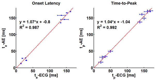
The results of the timing and SNR measurements from both heart A and B are tabulated in Table I, where they are sorted by stimulation location (AT, AP) and the electrode pairs (1–2, 2–3, and 3–4). Note that the measured uncertainty in the onset latency of both AE and ECG was relatively small, typically 1 to 3 ms. The width at −3 dB, a measure of the uncertainty in the peak position, was relatively large at 10 to 15 ms. The onset latency and the time-to-peak of AE and ECG signals are compared graphically in the scatter plots in Fig. 8. The upper and lower groups in the scatter plots correspond to measurements with atrial and apical stimulation, respectively. A linear fit through the data points was highly significant, R2 = 0.987 and R2 = 0.992 for onset latency and time-to-peak measurement, respectively. The unity slopes of the fitted lines tell us there was constant delay between AE and ECG while the intercepts, −0.8 ms for te and −1.04 ms for tp, show that this delay was very small.
TABLE I.
Timing Characteristics Measured from the Envelope of the AE and ECG Signals.
| Heart | SL | EL | te-AE [ms] | te-ECG [ms] | tp-AE [ms] | w−3 dB- AE [ms] | tp-ECG [ms] | w−3 dB- ECG [ms] | SNR-AE [dB] |
|---|---|---|---|---|---|---|---|---|---|
| A | AT | 1–2 | 168.8 ± 0.7 | 162.4 ± 0.9 | 171.3 | 6.8 | 167.8 | 16.6 | 15.7 |
| 2–3 | 165.4 ± 0.6 | 151.6 ± 2.0 | 169.1 | 9.9 | 160.4 | 19.6 | 13.5 | ||
| 3–4 | 145.4 ± 0.8 | 144.2 ± 12.0 | 149.1 | 9.2 | 150.2 | 11.0 | 11.1 | ||
| AP | 1–2 | 12.9 ± 1.1 | 14.4 ± 1.5 | 16.6 | 6.8 | 21.2 | 12.8 | 14.7 | |
| 2–3 | 22.4 ± 1.0 | 30.2 ± 1.8 | 49.8 | 6.2 | 49.8 | 13.2 | 10.2 | ||
| B | AT | 1–2 | 157.7 ± 0.8 | 135.0 ± 12.0 | 160.8 | 5.5 | 143.6 | 14.6 | 11.9 |
| 2–3 | 135.5 ± 0.4 | 133.0 ± 0.8 | 137.6 | 6.2 | 137.6 | 12.0 | 10.2 | ||
| AP | 1–2 | 28.3 ± 0.5 | 18.8 ± 1.7 | 31.4 | 8.0 | 25.4 | 14.0 | 13.4 | |
| 2–3 | 29.5 ± 0.8 | 28.3 ± 1.2 | 33.8 | 6.2 | 34.1 | 12.0 | 13.4 |
The parameters are illustrated in Fig. 4. The acronyms are as follows: SL = stimulation location, AT = right atrium, AP = apex, EL = electrode pair, tp = time-to-peak, te = onset latency, w−3 dB = the −3 dB width of the signal. AE = acousto-electric, ECG = low frequency electrocardiograms, SNR = signal-to-noise ratio.
Fig. 8.
Plots of the timing measurements tabulated in Table I demonstrating the relationship between the low-frequency ECG signals and the AE signals. These plots combine measurements from hearts A and B. In the plot on the left, the error bars are the measured uncertainty, while in the plot on the right, the horizontal and vertical error bars are the w−3 dB of the ECG and AE signals, respectively.
IV. Discussion
In this paper, we have described the first mapping of bioelectric current in a live rabbit heart using UCSDI. This demonstrates that UCSDI is a potentially viable cardiac mapping technique that could significantly improve intracardiac procedures.
Experimental results indicate that UCSDI provides spatial and temporal patterns of the propagating cardiac activation wave. Moreover, measurements were repeatable, dependent on the presence of ultrasound, and consistent with the simultaneously recorded ECG signals. The results of the control experiments in Fig. 5 indicate that the AE signal disappeared in the absence of ultrasound and was spatially localized to the correct anatomical location based on one-way acoustic propagation. In addition, Fig. 5 demonstrates that the AE signal occurred within the heart wall at the side facing the transducer, consistent with both the electrode placement and the orientation of the heart illustrated in Fig. 1.
Motion of the heart was suppressed with the excitation-contraction decoupler BDM, as demonstrated by the plot at the bottom of Fig. 7 displaying axial displacements. Not only was the maximum absolute displacement miniscule (10 μm), but it also occurred more than 100 ms after the electric signals. Motion during the electric signals was less than 5 μm, further suggesting that the AE signal was not influenced by motion.
According to the timing measurements illustrated in Fig. 8, there was good correlation of the onset time and time-to-peak between AE and ECG signals. The unity slope and the small intercept value of the fitted lines of these plots indicates there was minimal delay between the AE and ECG signals. The consistent timing between them further supports the electrophysiological origin of UCSDI.
Atrial and apical stimulation results in different propagation patterns. When the heart is stimulated at the apex, propagation of the activation wave is mostly parallel to the long axis of the heart, whereas when the heart is stimulated from the right atrium, the wave propagates mostly from the endocardium outward [23]. In Fig. 6, the ECG and AE signals occur at approximately the same slow-time, yet the AE signals occur at different x-positions. Because the recording electrodes were arrayed in the left ventricle parallel to the x-axis, this is consistent with what one would expect from a wave propagating from the endocardium outward.
Because the wave propagated parallel to the x-axis for data presented in Fig. 7, AE signals should be delayed in slow-time. Not only was there a delay between the signals measured with electrodes 1–2 and 2–3, but in the M-mode measured with 2–3, we also see that the signal spreads along a line at an angle with the slow-time axis. This strongly suggests that the AE signal captured a wave propagating along the x-axis in slow-time. The propagation velocity estimated from the slope of that line, 0.25 ± 0.05 mm/ms, is comparable both to that measured with ECG signals, as well as to what others have observed [24].
The morphology of the AE signals shown in Figs. 6 and 7 are of 2 types: a signal with either a single zero crossing (electrodes 1–2 in Figs. 6 and 7) or 2 zero-crossings (electrodes 2–3 in Fig. 7 and electrodes 3–4 in Fig. 6). We expect that the largest AE signals would be close to the recording electrodes because the lead fields are strongest in this region. The zero crossings in the AE signal could be interpreted as the time the wave passes a single electrode. A single zero-crossing suggests that one electrode was out of the imaging plane, whereas a signal with 2 zero crossings had both electrodes in plane. Notice also from the signal from (5) that the PSF of the ultrasound system will filter the signal along the slow-time axis.
The large PSF (6.9 mm × 4.8 mm) of the AE system was mainly due to the low-frequency transducer used. As a result of this large PSF and the relative proximity of the electrodes (3–6 mm), the maximum mapping distance from the electrodes was within the width of the PSF. In theory, the lead field strength of a monopolar electrode reduces by 12 dB per doubling of distance from the electrode. The system used in this proof-of-principle study is far from optimal. In future studies using transducers with higher center frequency, we will explore techniques that provide better electronic noise management with enhanced spatial resolution and sensitivity.
Another limitation of this study is that AE signals could not be acquired on all electrodes simultaneously due to hardware limitations. There were subtle changes in the heart between acquisitions that were reflected in the small interacquisition delays. However, these changes were small because the low-frequency signals acquired simultaneously for all acquisitions did not exhibit significant change in signal morphology.
From the AE traces shown in Fig. 5, the sensitivity of the method can be roughly estimated. The blue curve shows the maximum AE signal acquired while the control curves are appropriate estimates of system noise. According to the signal equation (5), the AE signal is a spatial sum that depends on several geometric factors. Assuming that the current source has constant magnitude and direction and is perfectly parallel to the electrode lead field within a resolution cell of the AE measurement system, we can extract the current source from the spatial sum. The spatial sum after extraction is a constant representing the sensitivity and is equal to the ratio of the maximum signal amplitude and maximum current density. From [25], [26], the current density of the activation wave is ~1 mA/cm2; therefore, the sensitivity is 0.71 μV/(mA/cm2). Accordingly, the noise level, or the smallest detectible signal with this setup, is 0.06 to 0.1 mA/cm2.
We have described for the first time the detection and mapping of biological current using UCSDI. UCSDI has great potential advantages as a tool to map arrhythmias during interventional cardiac procedures in which an ultrasound array and a sparse array of recording electrodes are integrated into an intracardiac catheter. The spatial resolution of UCSDI is determined by the focusing characteristics of the ultrasound beam. Electronic steering of the ultrasound beam would provide real-time electrical mapping of the heart. As the accompanying movies demonstrate, UCSDI images are automatically registered to the B-mode ultrasound, which suggests the possibility of dynamic feedback of mechanical and electrical cardiac events during ablation procedures and pacemaker insertion.
Supplementary Material
Acknowledgments
We would like to thank Nancy Roeser and Kimberly Ives for their generous help and training. We would also like to thank Adam Lauver and Erin Booth for their help with the Langendorff setup.
We gratefully acknowledge the support of the NIH through grants HL67647, EB003451, and HL082640; the Department of Biomedical Engineering at the University of Michigan; and the Fulbright Fellowship Program, U.S. Department of State.
Biographies
 Sheng-Wen Huang was born in 1971 in Changhua, Taiwan, R.O.C. He received the B.S. and Ph.D. degrees from National Taiwan University, Taipei, Taiwan, R.O.C., in 1993 and 2004, respectively, both in electrical engineering. He worked as a postdoctoral researcher at National Taiwan University from 2004 to 2005 and at University of Michigan from 2005 to 2008. Currently, he is a senior fellow at University of Washington. His research interests include optoacoustic transduction and imaging, ultrasound elasticity imaging, and thermal strain imaging.
 Congxian Jia received the B.S. degree and an M.S. degree in mechanical engineering from Beijing University, Beijing, P.R. China, in 1999 and 2002, respectively. She also received an M.S. degree in biomechanics of aerospace and mechanical engineering in 2004 from Boston University.
She is currently a Ph.D. candidate at the University of Michigan, working as a research assistant in the Biomedical Ultrasonics Laboratory. She is a student member of the IEEE. Her research interests include ultrasound elasticity imaging and its applications to cardiac diagnosis.
 Ragnar Olafsson received the B.S. degree in electrical engineering in 2002 from the University of Iceland, Reykjavik, Iceland. In 2002 he received a Fulbright Scholarship to pursue a graduate degree in biomedical engineering at the University of Michigan, Ann Arbor, Michigan, where he completed the M.S. and Ph.D. degrees in 2004 and 2008, respectively. He is currently working as a postdoctoral researcher with the Department of Radiology in the College of Medicine at the University of Arizona, Tucson, Arizona. His current research interests include imaging biopotentials using ultrasound and photoacoustic molecular imaging.
 Kang Kim received his B.S. degree in educational physics from Seoul National University, Seoul, South Korea, in 1986; an M.S. degree in physics from the University of Paris VI (Universite de Pierre et Marie Curie), Paris, France, in 1989; and a Ph.D. degree in acoustics from the Pennsylvania State University, PA, in 2002. Following his M.S. degree, he moved to the Agency for Defense Development (ADD), Chinhae, South Korea, as a research associate. He later held an appointment as a senior research associate, leading a SONAR development team since 1995. Following his Ph.D. degree in acoustics, Dr. Kim joined the Biomedical Engineering Department at the University of Michigan as a postdoctoral research fellow, mainly working on ultrasound tissue elasticity imaging in medical application. He later held a faculty appointment in the same department as an assistant research scientist. Currently, he is assistant professor of medicine in the Cardiovascular Institute, School of Medicine, and an assistant professor of bioengineering in the Department of Bioengineering, Swanson School of Engineering, University of Pittsburgh. His recent research interests include noninvasive ultrasound-based multimodal imaging techniques such as nonlinear tissue elasticity imaging, 3-D elasticity imaging, thermal strain imaging, photoacoustic molecular imaging, and engineered tissue characterization.
 Matthew O’Donnell (M’79–SM’84–F’93) received his B.S. and Ph.D. degrees in physics from the University of Notre Dame, Notre Dame, IN, in 1972 and 1976, respectively.
Following his graduate work, Dr. O’Donnell moved to Washington University in St. Louis, MO, as a postdoctoral fellow in the Physics Department working on applications of ultrasonics to medicine and nondestructive testing. He subsequently held a joint appointment as a senior research associate in the Physics Department and a Research Instructor of Medicine in the Department of Medicine at Washington University. In 1980, he moved to General Electric Corporate Research and Development Center in Schenectady, NY, where he continued to work on medical electronics, including MRI and ultrasound imaging systems. During the 1984–1985 academic year, he was a visiting fellow in the Department of Electrical Engineering at Yale University in New Haven, CT, investigating automated image analysis systems. In 1990, Dr. O’Donnell became a Professor of Electrical Engineering & Computer Science at the University of Michigan in Ann Arbor, MI. Starting in 1997, he held a joint appointment as Professor of Biomedical Engineering. In 1998, he was named the Jerry W. and Carol L. Levin Professor of Engineering. From 1999–2006, he also served as Chair of the Biomedical Engineering Department. During 2006, he moved to the University of Washington in Seattle, WA, where he is now the Frank and Julie Jungers Dean of Engineering and also a Professor of Bioengineering. His most recent research has explored new imaging modalities in biomedicine, including elasticity imaging, in vivo microscopy, optoacoustic arrays, optoacoustic contrast agents for molecular imaging and therapy, thermal strain imaging, and catheter-based devices.
 Russell Witte received a B.S. degree (with honors) in physics from the University of Arizona, Tucson, in 1993, and the Ph.D. degree in bioengineering in 2002. Following travel abroad in Europe and Brazil, he began graduate school at Arizona State University in bioengineering. His doctoral thesis exploited chronic microelectrode arrays to describe sensory coding and cortical plasticity in the mammalian brain. He then moved to the University of Michigan, Ann Arbor, to develop new ultrasound contrast mechanisms for imaging, especially brain, nerve, and muscle tissue. While at the Biomedical Ultrasonics Laboratory, he helped devise several novel imaging techniques involving ultrasound. Currently, he is an assistant professor of radiology and the director of the Experimental Ultrasound and Neural Imaging Laboratory at the University of Arizona, where he is engaged in research on new methods using a combination of light, ultrasound, and radiofrequency that potentially affect a variety of medical disorders from epilepsy to cancer.
References
- 1.Mickelsen S, Dudley B, Treat E, Barela J, Omdahl J, Kusumoto F. Survey of physician experience, trends and outcomes with atrial fibrillation ablation. J Interv Card Electrophysiol. 2005 Apr;12(3):213–220. doi: 10.1007/s10840-005-0621-6. [DOI] [PubMed] [Google Scholar]
- 2.Goldberger JJ. Atrial fibrillation ablation: Location, location, location. J Cardiovasc Electrophysiol. 2006 Dec;17(12):1271–1273. doi: 10.1111/j.1540-8167.2006.00669.x. [DOI] [PubMed] [Google Scholar]
- 3.Klemm HU, Steven D, Johnsen C, Ventura R, Rostock T, Lutomsky B, Risius T, Meinertz T, Willems S. Catheter motion during atrial ablation due to the beating heart and respiration: Impact on accuracy and spatial referencing in three-dimensional mapping. Heart Rhythm. 2007 May;4(5):587–592. doi: 10.1016/j.hrthm.2007.01.016. [DOI] [PubMed] [Google Scholar]
- 4.Greensite F. Heart surface electrocardiographic inverse solutions. In: He B, editor. Modeling and Imaging of Bioelectrical Activity: Principles and Applications. New York: Kluwer Academic/Plenum Publishers; 2004. pp. 119–160. [Google Scholar]
- 5.Daccarett M, Segerson NM, Gunther J, Nolker G, Gutleben K, Brachmann J, Marrouche NF. Blinded correlation study of three-dimensional electro-anatomical image integration and phased array intra-cardiac echocardiography for left atrial mapping. Europace. 2007 Oct;9(10):923–926. doi: 10.1093/europace/eum192. [DOI] [PubMed] [Google Scholar]
- 6.Zhong H, Lacomis JM, Schwartzman D. On the accuracy of cartomerge for guiding posterior left atrial ablation in man. Heart Rhythm. 2007 May;4(5):595–602. doi: 10.1016/j.hrthm.2007.01.033. [DOI] [PubMed] [Google Scholar]
- 7.Olafsson R, Jia C, Huang S-W, Witte RS, O’Donnell M. Detection of electrical current in a live rabbit heart using ultrasound. Proc. 2007 IEEE Ultrasonics Symp; New York, NY. pp. 989–992. [Google Scholar]
- 8.Witte R, Olafsson R, Huang SW, O’Donnell M. Imaging current flow in lobster nerve cord using the acoustoelectric effect. Appl Phys Lett. 2007;90(16) art. no. 163902. [Google Scholar]
- 9.Jossinet J, Lavandier B, Cathignol D. The phenomenology of acousto-electric interaction signals in aqueous solutions of electrolytes. Ultrasonics. 1998;36(1–5):607–613. doi: 10.1016/s0041-624x(00)00029-9. [DOI] [PubMed] [Google Scholar]
- 10.Jossinet J, Lavandier B, Cathignol D. Impedance modulation by pulsed ultrasound. Electrical Bioimpedance Methods: Applications to Medicine and Biotechnology. 1999;873:396–407. [Google Scholar]
- 11.Lavandier B, Jossinet J, Cathignol D. Experimental measurement of the acousto-electric interaction signal in saline solution. Ultrasonics. 2000 Sep;38(9):929–936. doi: 10.1016/s0041-624x(00)00029-9. [DOI] [PubMed] [Google Scholar]
- 12.Olafsson R, Witte RS, Kim K, Ashkenazi S, O’Donnell M. Electric current mapping using the acousto-electric effect. Proc SPIE, Medical Imaging 2006: Ultrasonic Imaging and Signal Processing. 2006 art. no. 614700. [Google Scholar]
- 13.Witte RS, Olafsson R, O’Donnell M. Acousto-electric detection of current flow in a neural recording chamber. presented at the 2006 IEEE Int. Ultrasonics Sym; Vancouver, BC, Canada. [Google Scholar]
- 14.Olafsson R, Witte RS, Huang SW, O’Donnell M. Ultrasound current source density imaging. IEEE Trans Biomed Eng. 2008 Jul;55(7):1840–1848. doi: 10.1109/TBME.2008.919115. [DOI] [PMC free article] [PubMed] [Google Scholar]
- 15.Olafsson R, Witte RS, O’Donnell M. Measurement of a 2d electric dipole field using the acousto-electric effect. Proc. SPIE, Medical Imaging 2007: Ultrasonic Imaging and Signal Processing; 2007. art. no. 65130s. [Google Scholar]
- 16.Zhang H, Wang LV. Proc SPIE, Photons Plus Ultrasound: Imaging and Sensing. 2004. Acousto-electric tomography; pp. 145–149. [Google Scholar]
- 17.Malmivuo J, Plonsey R. Bioelectromagnetism: Principles and Applications of Bioelectric and Biomagnetic Fields. xxii. New York: Oxford University Press; 1995. p. 482. [Google Scholar]
- 18.Tanhehco EJ, Yasojima K, McGeer PL, Washington RA, Lucchesi BR. Free radicals upregulate complement expression in rabbit isolated heart. Am J Physiol Heart Circ Physiol. 2000 Jul;279(1):H195–H201. doi: 10.1152/ajpheart.2000.279.1.H195. [DOI] [PubMed] [Google Scholar]
- 19.Kettlewell S, Walker NL, Cobbe SM, Burton FL, Smith GL. The electrophysiological and mechanical effects of 2,3-butane-dione monoxime and cytochalasin-d in the Langendorff perfused rabbit heart. Exp Physiol. 2004 Mar;89(2):163–172. doi: 10.1113/expphysiol.2003.026732. [DOI] [PubMed] [Google Scholar]
- 20.Witte RS, Hall T, Olafsson R, Huang SW, O’Donnell M. Inexpensive acoustoelectric hydrophone for mapping high intensity ultrasonic fields. J Appl Phys. 2008;104(1) doi: 10.1063/1.2974622. art. no. 054701. [DOI] [PMC free article] [PubMed] [Google Scholar]
- 21.Lubinski MA, Emelianov SY, O’Donnell M. Speckle tracking methods for ultrasonic elasticity imaging using short time correlation. IEEE Trans Ultrason Ferroelectr Freq Control. 1999 Jan;46:82–96. doi: 10.1109/58.741427. [DOI] [PubMed] [Google Scholar]
- 22.Lubinski MA, Emelianov SY, Raghavan KR, Yagle AE, Skovoroda AR, O’Donnell M. Lateral displacement estimation using tissue incompressibility. IEEE Trans Ultrason Ferroelectr Freq Control. 1996 Mar;43:247–256. doi: 10.1109/58.660158. [DOI] [PubMed] [Google Scholar]
- 23.Durrer D, van Dam RT, Freud GE, Janse MJ, Meijler FL, Arzbaecher RC. Total excitation of the isolated human heart. Circulation. 1970 Jun;41(6):899–912. doi: 10.1161/01.cir.41.6.899. [DOI] [PubMed] [Google Scholar]
- 24.Sung D, Omens JH, McCulloch AD. Model-based analysis of optically mapped epicardial activation patterns and conduction velocity. Ann Biomed Eng. 2000 Sep;28(9):1085–1092. doi: 10.1114/1.1314891. [DOI] [PubMed] [Google Scholar]
- 25.Malmviou J, Plonsey R. Bioelectromagnetism: Principles and Applications of Bioelectric and Biomagnetic Fields. chap 8. New York: Oxford University Press; 1995. Source-field models; pp. 148–158. [Google Scholar]
- 26.Liu ZM, Liu CG, He B. Noninvasive reconstruction of three-dimensional ventricular activation sequence from the inverse solution of distributed equivalent current density. IEEE Trans Med Imaging. 2006 Oct;25(10):1307–1318. doi: 10.1109/tmi.2006.882140. [DOI] [PubMed] [Google Scholar]
Associated Data
This section collects any data citations, data availability statements, or supplementary materials included in this article.


