Abstract
We have developed a technique to directly observe the micromechanics of the stem-cement and cement-bone interfaces of cemented femoral stems under physiologically relevant loading conditions. Thick transverse sections of a stem-cement-femur construct were fixed to the base of a test frame. Ante- & Retro-verting torques were applied to the femoral stem by screwing the stem (via a pair of through holes) to an axle, which was turned using a lever-arm actuated by the test frame cross-head. The surface of each transverse section was serially digitally imaged during loading. The displacements of the stem, cement & bone were determined using digital image correlation. These data were then used to calculate the relative displacements across the interfaces. This method provides a path to more thorough understanding of load-transfer from femoral stem to femur.
Keywords: Hip, THA, Arthroplasty, Cement, Micromechanics, Stem-cement-nterface, Cement-bone-interface, Micromotion, Cadaver, Retrieval
Introduction
The experimental mechanics of cemented femoral stems have been investigated previously using whole stem-cement-femur constructs. These laboratory model systems had the advantage that functional loads could be simulated, but they did not allow direct observation of load-transfer across the interfaces. To directly observe the micromechanics of the interfaces it was necessary to test subsections of the whole construct. Previously, we had observed the micromechanics of the cement-bone interface in small rectangular-prism sections tested in either compression, tension, or shear (Mann et al., 2008; Mann et al., 2009; Miller et al., IN PRESS). These studies were limited in that the small section size used (~ 8×4mm) could have disrupted material connectivity and altered the load transfer across the interface. A further limitation was that, with regard to the stem-cement interface, only bonded interfaces could be investigated in small sections. Load transfer across the more commonly occurring disbonded stem-cement interfaces could only be observed in circumferentially intact specimens. So, in order to quantify interface micromechanics under more realistic conditions, we developed methods to torsionally load whole transverse sections of cemented femoral hip replacements. We combined this loading method with an imaging approach that allowed quantification of the transverse plane micro-motion along the stem-cement and cement-bone interfaces. In this way, the functional response to loading of the construct could be quantified at all locations along the interfaces visible in the transverse section.
Experimental Methods
We have demonstrated our method using post-mortem retrieved stem-cement-femur constructs from three donors: #1: age 77yrs, unknown years in service; #2: age 92yrs, 6 years in service; #3: age 87yrs, 0.9 years in service.
Specimen preparation
The cadaveric femora were stripped of all soft tissue and distally potted to facilitate sectioning. Transverse sections of the stem-cement-femur constructs, with a thickness of 10mm, were created using a water irrigated saw (Isomet 2000, Buehler, Lake Bluff, IL). The 10mm scale, commonly used in the study of trabecular bone structures, was chosen so as to incorporate sufficient trabeculae to ensure structural integrity.
Two holes were drilled (2.26 mm diameter solid carbide bit with 135degree point angle) through the stem, equidistant to its centroid, to allow attachment of an axle to the back (distal side) of the stem. Care was taken to not load or overheat the interfaces during the drilling procedure: the transverse sections were clamped, via the stem alone, to a slab of aluminum and stem temperatures were kept below 37°C by interrupting the drill to allow cooling. Stem temperature was monitored using a type K thermocouple and multimeter.
A custom polycarbonate holding block was created for each transverse section using a computer numerical controlled (CNC) milling machine that followed a trace of the outer contour of the bone on a digital image. A 1.5mm gap was included between the polycarbonate block and bone periosteal surface to facilitate the introduction of adhesive. The periosteal tissue was carefully scraped from the bone surface and a two-component acrylic adhesive (Devcon Plastic Welder, Danvers, MA) was used to fix the bone surface to the polycarbonate holding block. To ensure that the specimens were correctly aligned, the adhesive was applied with the specimens mounted in the loading device described below. To facilitate optical displacement measurements, the specimens were speckled with black and/or white enamel aerosol paint, creating optical texture on the surface of the transverse section.
Mechanical testing
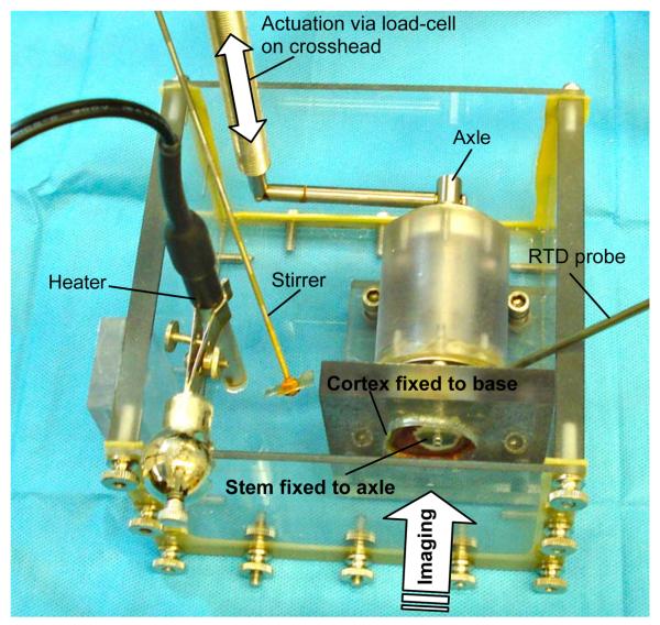
The custom torsional loading device consisted of an axle, supported by ceramic bearings fixed to the base of a mechanical test frame (Instron 1122, Norwood, MA), with a 72mm lever arm attached to the crosshead of the test frame. This device was held in a clear polycarbonate container filled with calcium buffered saline (Figure 1). The fluid was maintained at 37 ± 0.2 deg C using a 100W immersion heater driven, via a solid state relay (SSR330DC25, www.omega.com), by a proportional control system (CNi3254, www.omega.com) using feedback from a Platinum Resistance Temperature Detector (PR-11-2-100-1/8-6-E, www.omega.com).
Figure 1.
Apparatus for applying torque to the transverse sections of cemented femoral hip components. A torque was applied to the stem via an axle that was secured to the stem with two small screws. Torque was applied to the axle via a lever arm driven by the test frame actuator. The bone was glued into to a polycarbonate plate, which was fixed to the base of the test frame. The specimen was submerged in 37degC calcium buffered saline.
As an example of the methodology we will present data from reversing torques that were applied in displacement control (0.13 deg/sec) to limits of 0.73N-m in retroversion and 0.22N-m in anteversion. Prior to data acquisition, specimens were subject to 3 cycles of ante-retroversion, which was sufficient to establish a repeatable torque/rotation curve. Since we wished to ensure that these specimens were not damaged during this experiment, the retroverting torque was towards the lower bound of physiological loading – assuming even torque distribution and taking average data from Bergmann (2001), this torque was representative of that generated by a 78kg individual during gait or a 52kg individual during stair ascent.
Optical displacement measurement
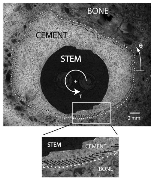
A digital image correlation (DIC) technique was used to quantify the micro-motion along the stem-cement and cement-bone interfaces (Figure 2). A CCD camera (Insight QE 4.2, Diagnostic Instruments, Sterling Heights, MI) with telecentric lens and 2x converter (Computar TEC-55) was used to sequentially image the stem, cement, and bone during mechanical loading. When viewing the whole cement mantle and adjacent bone, the resolution was about 0.025 mm/pixel. A commercial DIC software package (RapidCorrelator v1.0, http://www.softv.net/Public/xstreameng/solutions.htm) was used to determine displacements between anteverted and retroverted image frames for the entire construct. Measurements were made using sub-regions of 10 × 10 pixels (about 0.05mm2). To determine the relative motions across the stem-cement and cement-bone interfaces, a multi-step approach was used. First, contours of the interfaces were created in the anteverted reference image and sampling locations along the interfaces were defined at 2 degree increments (centered on the centroids of the stem and cement boundaries respectively). Sampling points on either side of the interface were then created at a distance of 0.25mm normal to the interface. This was done to insure that the sampled DIC sub-regions did not cross the material boundaries. The local motion at the sampling points were then determined by mapping the displacements from adjacent DIC sub-regions using linear shape functions. This approach accounted for the fact that the sampling points did not usually coincide with the sub-region grid (10 × 10 pixels) generated using the DIC software. The relative normal, shear, and total micro-motions were then determined as the differences in motion on either side of interface. The RMS error of DIC system was about 0.0012mm. Because micro-motion was calculated as differences in displacement between two DIC locations, potential errors could double, so the interface micromotion data was accurate to about 0.0025mm (0.1pixels).
Figure 2.
A digital image correlation technique was used to quantify displacements adjacent to the interfaces. This example, from donor bone #1, shows motion of cement (black vector lines) and bone (white vector lines) at the cement-bone interface. The differences between these vectors were computed and decomposed into relative normal and shear motion at the interface as a function of angular position (Figure 3).
Data analysis
The relative micro-motions across the interfaces were calculated between the extremums of loading. Both normal and shear components were calculated, and the total interface micro-motion was calculated as the vector sum of the normal and shear components for both cement-bone and stem-cement interfaces (Figures 2 & 3).
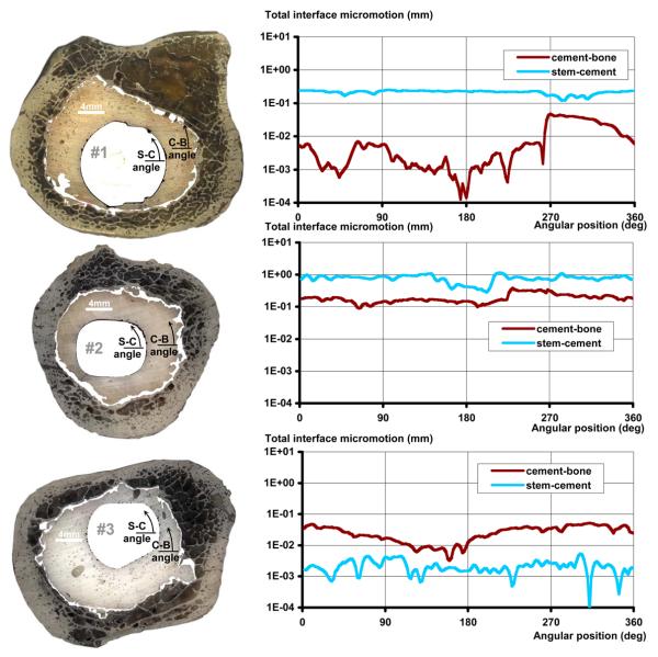
Figure 3.
Left: images of the transverse sections in which interface gaps have been highlighted using black (stem-cement interface) and white (cement-bone interface). Right: corresponding graphs of interface micro-motion for the stem-cement and cement-bone interfaces as a function of angular position. The angular position measures were centered on the centroids of the stem or cement perimeters, as appropriate.
Results
There was a wide range of responses to mechanical loading of the 10mm thick en bloc transverse specimens. For donors #1, #2 & #3: torsional stiffnesses were 393, 70, & 2147 Nm/deg; and spans were 1.8, 9.5 & 0.04 degrees. Micro-motion at the stem-cement and cement-bone interfaces also varied widely (Figure 3). The median of total (normal + shear) micro-motion at the interfaces spanned two orders of magnitude for both stem-cement (0.22, 0.80 & 0.002 mm) and cement-bone (0.004, 0.17 & 0.027 mm) interfaces. There was no sign of damage being induced by testing, but specimen #2 had an open through crack (probably caused by the in vivo trauma implied by a healed fracture of the distal femur).
Discussion
We have demonstrated a method to examine the micromechanics of cemented interfaces under loads and constraints that resembled in vivo conditions more closely than had been possible using circumferentially incomplete sections. We demonstrated the utility of this method in measuring relative displacements across the interfaces, but it could also be used to quantify other outcomes. With appropriate care in the selection of axle and screw size, the technique could be used to explore both single cycle and fatigue failure of the interfaces. This method could also be used to examine cement strains and, with suitable magnification and resolution, strain in the trabeculae, thus giving a more complete picture of load-transfer between the stem and the bone. An additional advantage of this method was that it could be combined with other observations made on the same transverse section. For example, measures of interface morphology and damage to cement or bone could be quantified and related to the micro-mechanics data.
Limitations
In general, and certainly at the level of the studied sections, cemented stem interface loading is dominated by long-axis torque and axial load. Our techniques for the observation of motions in transverse sections required in-plane loading, so we only applied torque. This seemed reasonable since failure due to torsional loads has been indicated as an important mechanism of aseptic loosening both by computational studies showing increased damage accumulation for stair-climbing versus gait (Stolk 2002) and by increased early retroversion of femoral stems that were later revised (Karrholm 1994). However, the application of a simultaneous axial force would alter the loads and displacements at the interfaces. Further work is required to quantify the effect of combined loading, which would require a 2-camera DIC system to capture out-of-plane motion. The act of sectioning inevitably introduced some artefact, especially due to the interruption of out-of-plane trabeculae. The 10mm specimen thickness was chosen to ensure that a reasonable quantity of trabeculae were included without making the drilling process too arduous or torque requirements too high.
Acknowledgements
This work was supported by NIH AR42017. Some materials used in this study were procured through funding from NIH EB001715 with the assistance of Alan W Eberhardt at the University of Alabama-Birmingham (UAB). The authors also wish to acknowledge the assistance of Dan Jaeger of Upstate Medical University and Preston Beck (UAB) with specimen procurement.
Footnotes
Publisher's Disclaimer: This is a PDF file of an unedited manuscript that has been accepted for publication. As a service to our customers we are providing this early version of the manuscript. The manuscript will undergo copyediting, typesetting, and review of the resulting proof before it is published in its final citable form. Please note that during the production process errors may be discovered which could affect the content, and all legal disclaimers that apply to the journal pertain.
Conflict of Interest Statement
Amos Race, Mark A. Miller & Kenneth A. Mann have no conflicts of interest to report.
REFERENCES
- Bergmann G, Deuretzbacher G, Heller M, Graichen F, Rohlmann A, Strauss J, Duda GN. Hip contact forces and gait patterns from routine activities. Journal of Biomechanics. 2001;7:859–71. doi: 10.1016/s0021-9290(01)00040-9. [DOI] [PubMed] [Google Scholar]
- Karrholm J, Borssen B, Lowenhielm G, Snorrason F. Does early micromotion of femoral stem prostheses matter? 4-7-year stereoradiographic follow-up of 84 cemented prostheses. Journal of Bone & Joint Surgery - B. 1994;6:912–7. [PubMed] [Google Scholar]
- Mann KA, Bartel DL, Ayers DC. Influence of stem geometry on mechanics of cemented femoral hip components with a proximal bond. Journal of Orthopaedic Research. 1997;5:700–6. doi: 10.1002/jor.1100150511. [DOI] [PubMed] [Google Scholar]
- Mann KA, Miller MA, Cleary RJ, Janssen D, Verdonschot N. Experimental micromechanics of the cement-bone interface. Journal of Orthopaedic Research. 2008;6:872–879. doi: 10.1002/jor.20575. [DOI] [PMC free article] [PubMed] [Google Scholar]
- Mann KA, Miller MA, Race A, Verdonschot N. Shear fatigue micromechanics of the cement-bone interface: An in vitro study using digital image correlation techniques. Journal of Orthopaedic Research. 2009;3:340–346. doi: 10.1002/jor.20777. [DOI] [PMC free article] [PubMed] [Google Scholar]
- Miller MA, Eberhardt A, Cleary RJ, Verdonschot N, Mann KA. Micro-mechanics of post-mortem retrieved cement-bone interfaces. doi: 10.1002/jor.20893. IN PRESS. [DOI] [PMC free article] [PubMed] [Google Scholar]
- Stolk J, Verdonschot N, Huiskes R. Stair climbing is more detrimental to the cement in hip replacement than walking. Clinical Orthopaedics & Related Research. 2002;405:294–305. doi: 10.1097/00003086-200212000-00037. [DOI] [PubMed] [Google Scholar]


