Abstract
Control of the position, growth and subsequent function of living cells is a fundamental problem in tissue and cellular engineering. The development of a generation of ‘smart’ biomaterial substrates requires strict control over the material’s surface properties, because the initial response of the cultured cells to the biomaterials mainly depends upon the surface characteristics of the engineered material. Since most of the cells in the body are arranged in distinct patterns during development, it would be beneficial if one could create patterned environments in-vitro for regulating cell behavior, for applications in vivo, in particular for CNS neurons. Accordingly, in this article, we provide design strategies and methodologies developed for nano- and micro-scale surface patterning and the subsequent control of cellular responses in-vitro.
Keywords: Biomaterials, self assembled monolayers, surface patterning, neurons, cell engineering
1. Introduction
1.1 Surface modification of biomaterials
Regulating cell behavior at a biomaterial’s interface is of great importance in order to enable defined biological activity. This requires strict control over the material’s surface properties, because the initial response of cultured cells in contact with the engineered material mainly depends upon the surface characteristics of the biomaterial. The modification of the outermost surface of a biomaterial may allow for the creation of enhanced products with improved characteristics in regards to cellular compatibility and chemical functionality. Good biointegration, i.e. cell-material interaction, is the ideal outcome expected from a biomaterial, which is in many ways influenced by the surface properties of the biomaterial rather than its bulk properties. Therefore, designing a biomaterial with superior surface properties, without altering its key bulk properties, should be favorable for biochemical and biological functions as well as being of great importance in cellular engineering (Ratner and Bryant 2004).
Surface modification is a process that changes considerably the surface composition, structure and topography of a material. Surface modification of any biomaterial typically falls into two categories; (i) either the chemical or physical alteration of the atoms or molecules on the surface of a biomaterial, or (ii) coating the surface of a biomaterial with biocompatible and/or bioactive agents that are favorable for cell growth and/or subsequent function. There have been many techniques used to modify the surface of a biomaterial and they mainly fall under two major categories, chemical and topographical (Stevens and George 2005; Molnar, Hirsch-Kuchma et al. 2006). Surface chemistry and topography (surface structure) of biomaterial substrates have a great influence on regulating cell behavior, such as adhesion, migration, orientation, guidance, differentiation, proliferation, gene expression and protein synthesis (Kleinfeld, Kahler et al. 1988; Dulcey, Georger et al. 1991; Ravenscroft, Bateman et al. 1998; Stenger, Hickman et al. 1998; Jenney and Anderson 1999; Saneinejad and Shoichet 2000; Craighead, James et al. 2001; Andersson, Olsson et al. 2003). This is due to the fact that during natural development the same types of extracellular signals are regulating many cellular functions. In the case of engineered materials, cells as well as proteins and other essential biological substances make initial contact with the material’s surface, both in-vitro and in-vivo. Designing and modifying the surface of a biomaterial so that it is suitable to regulate cellular functions as well as guide cell behavior is, therefore, of great importance for a variety of biological and biomedical applications, in particular cell-based biosensors and scaffold-based tissue engineering (Jung, Kapur et al. 2001; Grayson, Shawgo et al. 2004; Dvir, Tsur-Gang et al. 2005; Khademhosseini, Langer et al. 2006). A key challenge for those applications is the ability to integrate synthetic (biomaterials) and living (cells) components in appropriate conditions that support the organization and assembly of cells into a functional state. In this regard, adhesion and controlled spreading of the cells onto the biomaterials can be a critical prerequisite for the success of engineering physiologically functional cell-based systems. This step primarily depends on the surface properties of the biomaterials. Surface modification of biomaterials is therefore of great importance for cellular engineering, and may be considered one of the most significant tools in the organization of cells into a functional systems or tissue engineered constructs, especially for applications in neuronal systems.
1.2 Concept of surface patterning
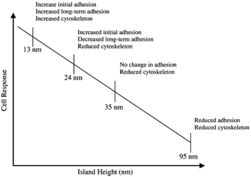
Control of the cell’s position, growth and subsequent function is one of the fundamental focuses in the development of a new generation of biomaterial substrates for use in cellular engineering. The inspiration for this approach is that all of the cells in the body are arranged in distinct patterns during development and these cellular patterns are organized by spatial and time-dependent environmental cues over many scale lengths, typically from nano and meso to micro and macro levels. Although all of these levels are equally important for the proper development of an organism, at the molecular and cellular level, nano-features play an important role in regulating essential cellular functions (see Table 1) (Yim and Leong 2005). Recent investigations also suggest that cells show a strong response to nano-structured surfaces in terms of increased cell adhesion, differentiation, proliferation, cytoskeleton development and gene expression (Curtis and Wilkinson 1997; Flemming, Murphy et al. 1999; Desai 2000; Craighead, James et al. 2001; Dalby, Childs et al. 2003). For example, Dalby, M. J. et al. (2002) demonstrated the increased, long-term cell adhesion (endothelial cells) and subsequent cellular responses to nano-featured surfaces (islands of 13 nm height) formed by the polymer de-mixing method (phase separation) (Dalby, Riehle et al. 2002). Another study by this group investigated the reaction of endothelial cells to nano-featured surfaces with different nano-island heights (13, 35, and 95 nm) and revealed that, although cells responded to all the nano-structured surfaces, the shortest (13 nm) nano-islands were the most effective at enhancing initial cell adhesion, long-term cell adhesion, and the development of a well-defined cytoskeleton (see Fig. 1) (Dalby, Giannaras et al. 2004). A third study by this group investigated the effect of these nano-featured surfaces using fibroblasts and observed rapid cellular adhesion as well as the production of a higher number of filapodia (a cell sensing element) on the surfaces with islands of 13 nm height when compared to those cultured on flat control surfaces (Dalby, Riehle et al. 2002). In addition, these nano-featured surfaces promoted cell proliferation, cytoskeletal organization and gene expression. These studies, in addition to others, have clearly indicated the impact of nano-features in dictating cell behaviors in which cells are able to sense features smaller than 10 nm. This is because, at the most fundamental level, cells in the body exist within a complex and dynamic environment featuring many examples of nano-patterned topography. For example, the extracellular matrix (ECM) protein collagen (the most abundant structural protein of the mammalian ECM) has a 65 nm repeat banding pattern of a helical structure. Also, the basement membranes are comprised of nanometer-sized pores, ridges and fibrous structures in a spatially-controlled manner (Yim and Leong 2005). All these data suggest that spatially-controlled nano-featured environments are essential for the proper function of cells, in addition to the biochemical microenvironment (Arnesen, Mosler et al. 2004). Therefore, the development of technologies for the creation of spatially-controlled substrates with suitable surface chemistry and topography is of interest for the generation of spatially-organized functional cells. These materials could eventually lead to the understanding of the complex co-ordination of cell-cell communication and cell-substrate interaction during development and tissue repair functions (Ito 1999; Jung, Kapur et al. 2001; Falconnet, Csucs et al. 2006). Cellular interactions are primarily influenced by biochemical as well as topographical cues. Therefore, another key step for making an ideal biomaterial is to integrate chemical and topographical cues in order to generate a cell-friendly environment that will eventually regulate cell function and guide growth over longer periods of time and under physiological conditions. All available information supports the importance of surface patterning of biomaterials in different size regimes, ranging from nano to micro, for use in cell engineering as well as to study the fundamental aspects of cell behavior, such as adhesion, migration, orientation, guidance, differentiation, proliferation, gene expression and protein synthesis.
Table 1.
Response of various cell types to synthetic surfaces with nanotopography (Yim and Leong 2005).
| Cell type | Ordered pit/ pillar | Demixed island | Column | Gratings/groove/step | Eletrospun fiber | Etched nanofeature | Carbon fiber |
|---|---|---|---|---|---|---|---|
| Fibroblasts | Decreased adhesion | Increased adhesion with decreasing height (<35 nm); enhanced cytoskelcton organization (height ≤13- nm)Changcs in cDNA cypres sion | Decreased cell adhesion; diffused network; increased filopodia; increased endocytic activity | Increased ECM production and higher proliferation | Deacreased adhesion | ||
| Smooth muscle cells | More spread and enhanced cytoskelcton organization | Cell alignment with nano-gratings; decreased proliferation | Increased cell adhesion and proliferation; cell aligned with fibers and assumed contractile phenotype | Increased adhesion and incrcasd prolifcratkjn | |||
| Endothelial cells | Increased adhesion and prolifcratkjn (depending on surface chemistry) | ||||||
| Macrophages | Higher phagocytic activity and enhanced spreading (height >71 nm) | ||||||
| Leukocytes | Increased expression of CD29, CD54, and CD 166 | ||||||
| Ostcoblasts | Increased alkaline, phosphatase expressnm and calcium deposition; increase osteoblast adhesion and protein adsorption | ||||||
| MSC | Cbond to genie and osteogenic differentiation; better mechanical properties | ||||||
| Neurons | Increased cell adhesion and viability | ||||||
| Hepatoccytcs | Formation of smaller spheroids and reduced detachment | ||||||
| Epithelial cells | Less spread, more stellate; reduced IL6 and IL8 production | Partial alignment with pattern, hut showed no difference in cytokine production |
ECM, Extracellular matrix; MSC, mesenchymal stem cells.
Fig. 1.
Drawing depicting the relationship between a PS/PBrS (polystyrene and poly(4-bromostyrene) island size and fibroblast response [Adapted with permission from Dalby, M. J. et al., Rapid fibroblast adhesion to 27 nm high polymer de-mixed nano-topography, Biomaterials, 25, 77, 2004].
1.3 Scope of the article
Considering the aforementioned issues, in this article, the authors focused their attention on the surface patterning of biomaterials suitable to control cell behavior. Design strategies and methodologies involved in nano- and micro-scale surface patterning will be introduced and brief experimental examples will be given on how the patterned surfaces influence cellular growth and behavior. The authors are not suggesting that any one particular technique could be ideal for cellular engineering or for this to be an exhaustive literature review of the topic, as the key intention is to stimulate research on surface patterning of biomaterials, in the form of self-assembled monolayers (SAMs), as well as to formulate such patterned biomaterial substrates as a promising synthetic ECM to modulate cellular behavior. It should be useful as a reference for a reader to gain insight on the surface patterning of biomaterials with SAMs and thus lead to initial design strategies for a researcher to begin these investigations.
2. Methods of surface patterning as applied to biomaterials
Patterning is an approach for the generation of novel interfaces on bulk biomaterials by controlling surface chemistry and topography to facilitate spatially-controlled cell growth and subsequent function. Thereby, it has considerable interest in the fields of cell-based biosensors and scaffold-based tissue engineering. The process of surface patterning allows direct control over a cell’s adhesion to desired regions of a substrate material, and inhibits their adhesion to undesired regions; thus, forming bi-phasic regions of adhesive and non-adhesive surfaces on the same substrate material (Kleinfeld, Kahler et al. 1988; Dulcey, Georger et al. 1991; Hickman, Bhatia et al. 1994; Spargo, Testoff et al. 1994; Kumar, Wang et al. 2003; Tourovskaia, Barber et al. 2003; Veiseh, Wickes et al. 2004; Welle, Horn et al. 2005; Falconnet, Csucs et al. 2006; Khademhosseini, Langer et al. 2006; Molnar, Hirsch-Kuchma et al. 2006). By functionalizing surfaces with signaling molecules or by the creation of guidance patterns not only the placement of cells can be determined, but also their differentiation and process growth (Kleinfeld, Kahler et al. 1988; Dulcey, Georger et al. 1991; Hickman, Bhatia et al. 1994; Ravenscroft, Bateman et al. 1998; Stenger, Hickman et al. 1998; Oliva, James et al. 2003; Kaehr, Allen et al. 2004; Romanova, Fosser et al. 2004; Sanjana and Fuller 2004; Li and Folch 2005; Molnar, Hirsch-Kuchma et al. 2006). These types of patterned surfaces can serve as model systems for the study of the fundamental aspects of cell-substrate and cell-cell interactions, which is necessary for engineering physiologically functional cellular systems, as well as in applications such as spinal cord repair and the development of prosthetic devices and materials.
Patterning of biomaterial surfaces can be done by a variety of methods using micro-and nano-fabrication technologies (Geissler and Xia 2004; Molnar, Hirsch-Kuchma et al. 2006). Most of these methods were originally adapted from the microelectronics field where they were used for the fabrication of integrated circuits and other miniature electronic components. The process of patterning surfaces can be broadly grouped into two categories: chemical and topographical. In general, initial cell adhesion is modulated by chemical patterning, but the cell growth can be controlled by both chemical and topographical patterning, as there is a complex interaction between topographical and chemical cues in guiding cell behavior (Li and Folch 2005). In the following sections, patterning of SAMs will be discussed in detail with special emphasis on how these methods can be adapted for producing spatially-oriented cellular structures and, consequently, evoke specific cellular responses.
3. Self assembled monolayers (SAMs)
SAMs, a good example of chemical patterning (Hickman, Bhatia et al. 1994; Mrksich and Whitesides 1995; Smith, Lewis et al. 2004; Yan, Huck et al. 2004; Senaratne, Andruzzi et al. 2005), are versatile molecular assemblies that are generally used to modify the properties of biomaterial surfaces with enhanced functionalities that are suitable for many demanding applications, particularly cell-based biosensors and tissue engineering, because SAMs are known to influence cell attachment (Georger, Stenger et al. 1992; Stenger, Pike et al. 1993; Hickman, Bhatia et al. 1994; Spargo, Testoff et al. 1994; Mrksich and Whitesides 1996; Ostuni, Yan et al. 1999). The preparation of SAMs is basically a ‘bottom-up’ approach that facilitates the assembly of unidirectional, ultra thin layers (typically in the order of nanometer thickness) on a solid surface using the appropriate SAMs precursors (chemical varieties). By the spontaneous organization of their constitutes via covalent bonding (chemisorption) or non-covalent bonding (physisorption), and based upon the electrostatic, hydrophobic, and Van der Waals interactions, they can lead to a thermodynamically stable, closely packed and well-ordered final structure suitable for multi-purpose applications (Ulman 1991; Ulman 1991; Ulman 1996). Because of their simplicity, flexibility and versatile functionality, SAMs of organic as well as inorganic chemical components are very popular and widely used in the patterning of cells and proteins in order to study the fundamental aspects of synthetic (organic) and biological interfaces. SAMs can also be modified further using crosslinking chemistry, or chemical modification after immobilization, in order to tailor their properties to specific applications. Thus, it has considerable interest in various biological, biotechnological and biomedical applications.
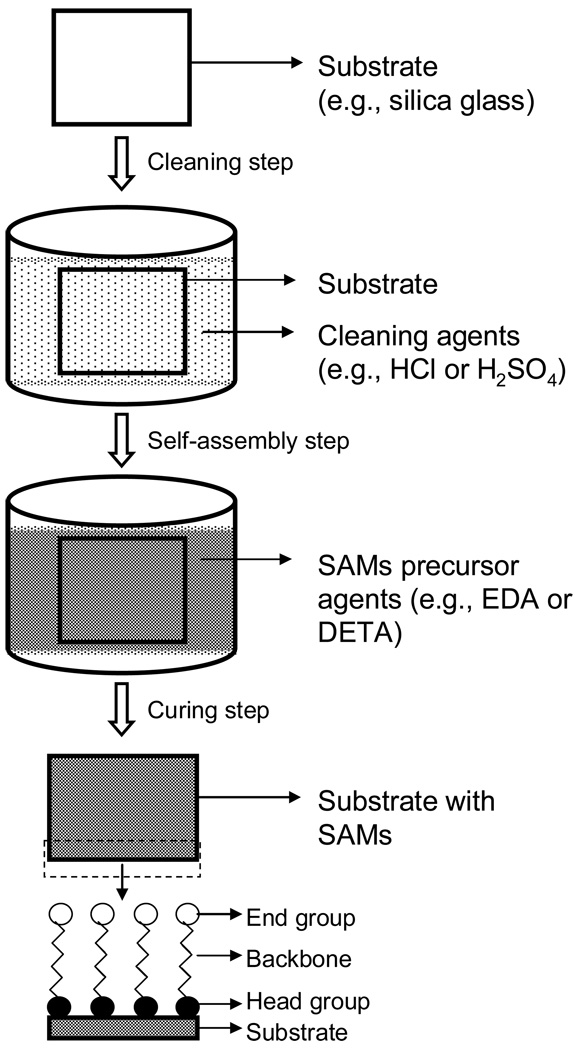
The formation of molecular monolayers by self-assembled adsorption was first initiated by Bigelow et al. (Bigelow, Pickett et al. 1946) in the 1940s, in which they reported a process for the formation of monolayer coatings of surfactants onto platinum substrates. In this time period, SAMs were not extensively utilized probably due to the lack of sophisticated analytical methods for the investigation of structural and other functional characteristics. Considerable attention was given to SAMs in the period of the early 1980s when Nuzzo and Allara reported the preparation of SAMs using alkanethiolates onto gold surfaces (Nuzzo and Allara 1983). Also, techniques were also being developed during this time for their analysis on microstructure surfaces (Laibinis, Hickman et al. 1989; Hickman, Ofer et al. 1991; Hickman, Ofer et al. 1991). Since then, a variety of SAMs has been developed with different functional groups for various applications. Among them, silane- and thiol-based SAMs are the most popular and well characterized systems for cellular applications. Fig. 2 shows a schematic illustration of SAM formation. In general, SAMs are prepared on a metal (i.e. gold) or hydroxyl-terminated substrates (i.e. silica glass). In this approach, the solid substrate is first cleaned with a cleaning agent (such as: HCl and H2SO4) and then placed into a solution containing the SAMs precursors in order to facilitate the self-assembly process via the chemisorption mechanism. This method has provided a straightforward way to obtain well-ordered monolayers. The SAMs formed by this method are both chemically and thermally stable (Schlenoff, Li et al. 1995). The chemical stability of SAMs relies on either covalent or non-covalent bonding based on the electrostatic, hydrophopic, or Van der Waals forces between adjacent molecules, depending upon the type of chemical reaction. For thiols, thermal stability depends upon the reaction and curing temperature and time; for instance, initial heating of SAMs has been shown to improve its quality (Schlenoff, Li et al. 1995), while a longer time and higher temperature generally result in desorption. It also depends on the chemical type used in the reaction. Other factors that affect the formation of SAMs include moisture content of the solvent or solution, concentration of the reaction solution containing the SAM precursors, purity (cleanliness), wettability and roughness of the solid substrate, as well as environmental factors such as air atmosphere, temperature and humidity, and reaction time (Ferguson, Chaudhury et al. 1993; Parikh, Allara et al. 1994; Valiokas, Svedhem et al. 1999; Du, Wood et al. 2000). The formation of SAMs can be confirmed by using various analytical tools, including X-ray photoelectron spectroscopy (XPS) and Auger Electron Spectroscopy (AES) (for surface composition), ellipsometry (for monolayer thickness), scanning tunneling microscopy (STM) or atomic force microscopy (AFM) (for monolayer roughness), and contact angle goniometry (for wettability). In the following sections, the formation of silane-based SAMs, the patterning of the SAMs, and their ability in controlling cellular functions are discussed with experimental examples.
Fig. 2.
Schematic illustration of SAMs formation.
3. 1 Formation of silane-based SAMs
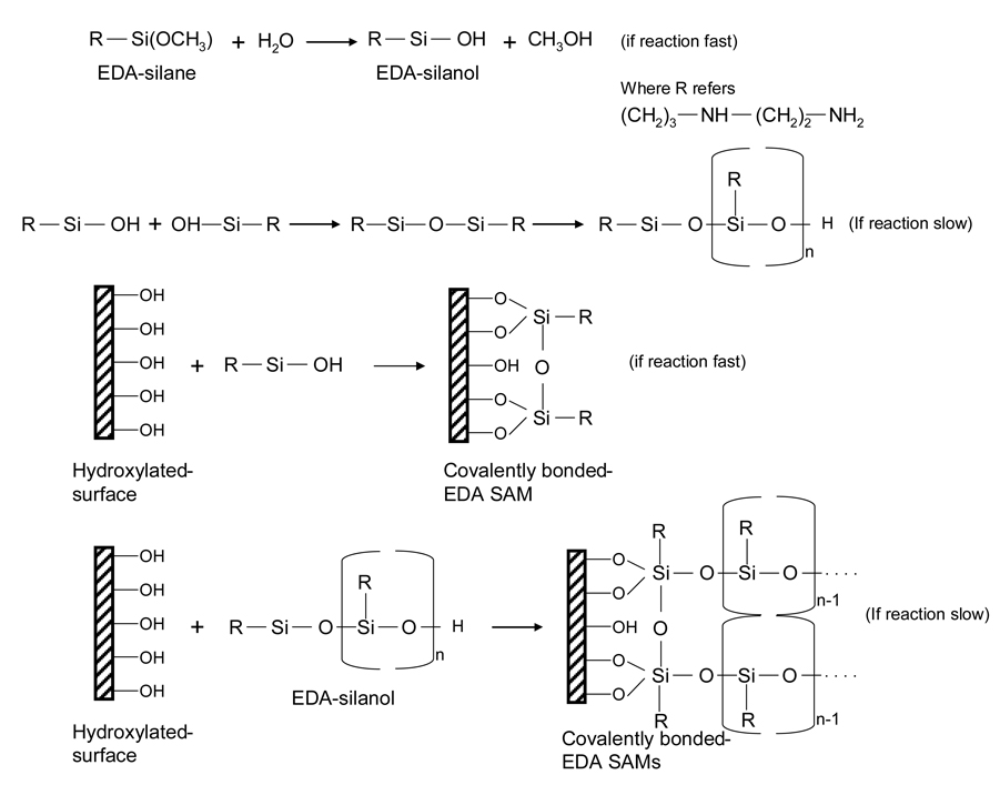
Cytophilic silane-based SAMs can be formed by the reaction of aminosilanes (i.e. N-2-aminoethyl-3-aminopropyl trimethoxysilane (EDA), NH2(CH2)2NH(CH2)3Si(OCH3)) with hydroxyl-terminated surfaces (i.e. silica glass) with a suitable organic solvent under ambient conditions. The reaction takes place spontaneously due to the strong chemical interactions between the silane and the hydroxyl groups. A schematic chemical strategy that involves the formation of EDA SAMs onto a silica glass substrate is illustrated in Fig. 3. The reactive silane groups first undergo hydrolysis to form corresponding silanols in the presence of a solvent and water (catalyst) medium. The hydroxyl groups of the silanol condense with those on the hydroxylated-glass substrate and with the hydroxyl groups on other silanols via Si–O–Si bonds (siloxane linkage) and then are covalently coupled to hydroxyl groups on the glass substrate, resulting in EDA SAM formation. Note that all the surface silanols do not necessarily react with one silane functional group and in many cases do not form a well-ordered monolayer, but can form a reaction site limited monolayer (Stenger, Georger et al. 1992). In this investigation, Stenger et al. (1992) reported the formation of EDA SAMs onto a silica glass substrate. In brief, first the glass substrates were cleaned prior to SAMs formation by immersion in HCl/methanol (1:1) (v/v) followed by concentrated H2SO4 for 30 min at room temperature. After acid cleaning, the substrates were thoroughly rinsed with deionized water and transferred to boiling water for 15–30 min. The EDA SAMs were formed by the reaction of the cleaned substrates with freshly prepared reaction solution for 15 min at room temperature. To make the reaction solution, 1% (v/v) of EDA was dissolved in 94% (v/v) 1 mM acetic acid in anhydrous methanol and 5% water (as catalyst) by volume. After the reaction, the silanated-glass substrates were rinsed in methanol three times and then baked for 5 min at 120ºC in order to eliminate any residual solvent (methanol) and to terminate the reaction of the aminosilane. The authors have also prepared a cytophobic SAM using another chemical moiety called tridecafluoro-1,1,2,2-tetrahydrooctyl-1-dimethylchlorosilane (13F), (CF2)5(CH2)2Si(CH3)2Cl, either directly onto pure EDA (as a control) or onto photolithographically-irradiated EDA substrates by immersing them in a solution of 13F (1.0–2.0%) dissolved in a suitable organic solvent (toluene, for example) for 0.5–3 h at room temperature, followed by rinsing three times in the same solvent and then baked for 5 min at 120ºC. This baking step facilitates the quick removal of residual solvent (toluene) and stops the reaction of alkylsilane. The formation of monolayers can be confirmed by various analytical methods, as described earlier, and the results of all the experimental data confirmed the formation of a SAM.
Fig. 3.
Chemical strategy of EDA SAMs formation onto a glass substrate.
As another important class of aminosilane, SAMs of trimethoxysilylpropyl diethylene triamine (DETA), H2N-(CH2)2-NH-(CH2)2-NH2, were developed for patterning cells. Basically, DETA is a cell-attachment promoting organic compound and, thus, it is widely used in cell patterning studies. Hickman et al. (1994) (Hickman, Bhatia et al. 1994) reported the formation of DETA SAMs onto glass substrates using the same protocol as described above (Stenger, Georger et al. 1992). They have also prepared 13F SAMs for backfilling purposes to ensure that the cells attached and migrated only on the DETA patterns. The SAMs made from DETA and 13F have been used as an in-vitro model system for the patterning of neuronal cells. The reasons for the selection of those two organic compounds for SAM preparation are (i) DETA contains amino functional groups that are hydrophilic and promote cell attachment and growth, and (ii) 13F contains fluorine functional groups that are hydrophobic and inhibit cell attachment and growth. SAMs that contains these two surfaces (DETA and 13F) in a spatially-controlled fashion can be used to control neuronal cell adhesion and outgrowth. They have also prepared SAMs with other organic compounds (EDA, for example) and compared the results with the DETA system by evaluating their suitability in hippocampal neuronal cell culture. The results suggested that DETA SAMs promoted the adhesion and growth of hippocampal neurons better when compared to other SAM surfaces, which indicated DETA as the best synthetic surface for neuronal cell studies to date (Schaffner, Barker et al. 1995).
The formation of SAMs was also carried out in a non-aqueous medium, which contrasted the above studies where added water was used as the catalyst. For example, Ravenscroft et al. carried out the formation of DETA SAMs without adding water in the reaction medium, but utilized the H2O present in the ambient atmosphere (Ravenscroft, Bateman et al. 1998). In brief, clean glass coverslips were first immersed into the reaction solution made from 0.1% (v/v) DETA dissolved in dry toluene and heated on a hot plate for 30 min at a temperature just below the boiling point of the solvent. The reaction solution was prepared in a nitrogen controlled glove box in order to minimize the exposure to moisture. The reaction mixture was then transferred out of the box to the ambient atmosphere and the coverslip immersed with the solution. After the reaction, the coverslips were rinsed thoroughly three times in the same solvent (toluene), immersed again in toluene and heated for 30 min just below the boiling point of the solvent. Finally, the DETA-coated coverslips were oven dried for 2 h. In another study DETA SAMs were evaluated for their suitability in embryonic hippocampal cell adhesion and growth studies along with other control surfaces (such as poly-D-lysine and 13F) (Schaffner, Barker et al. 1995). The studied characteristics included cell survival, and neurite outgrowth,. The results indicated that survival and neurite outgrowth of cells cultured on DETA were comparable to those cultured on poly-D-lysine, while cell survival on 13F SAMs was poor and the neurons were excessively aggregated with minimal neurite formation. Thus, DETA SAMs may be considered as the best surface for defined in vitro neuronal systems. All these experimental examples clearly indicate the potential use of silane-based SAMs in fundamental cell biological studies, as well as in application-oriented neuronal systems.
4. Patterning of self assembled monolayers
Patterning of SAMs is one of the established ways for positioning cells or proteins into desired regions in order to control the shape, growth and function of cells. A wide variety of techniques have been developed in the last two decades for the patterning of SAMs, including a conventional method, photolithography, and an unconventional method, microcontact printing (µCP) (Geissler and Xia 2004). These techniques are primarily applied to the production of micro- or nano-patterned surfaces suitable for controlled cell adhesion or protein adsorption. Some of the techniques used in patterning of SAMs are listed in Table 2 with their potential applications (Senaratne, Andruzzi et al. 2005). Each method has its own advantages and disadvantages, so selection of the right method purely depends upon the specific purpose of the experiment and the availability of the equipment necessary for each type of method. In the following sections, the applications of photolithography and µCP in producing patterned surfaces are discussed with detailed experimental examples.
Table 2.
Patterning techniques and applications (Jenney and Anderson 1999).
| Patterning technique | Features | Applications | Substrate |
|---|---|---|---|
| 1. Photolithography | |||
| (a) Photoresist coated substrate | <10µm | Alkyl-and amino-functionalized silanes for controlled cellular growth, protein immobilization and enzymatic assays | Silicon, SiOx, fused silica, glass |
| (b) Selective chemistry | Protein immobilization | Silicon, gold | |
| 2. UV lithography | |||
| (a) Deep UV (193nm) radiation exposure to induce photo-chemical changes on functional silanes | 100µm | Controlled cell growth on EDA and perfluorinated alkylsilanes | Glass, fused silica |
| 1µm | Protein immunoassays on OTMethoxysilane | SiOx | |
| 100µm | Controlled cell growth EDA and OTS | SiOx | |
| 25µm | Thiol-terminated silanes protein immunoassays | SiOx | |
| 100µm | OTS and APTS and chemically-modified amine with a synthetic peptide-derived from the B2 chain of laminin | SiOx | |
| (b) Alkanethiols | 208µm grooves | Biotin-streptavidin recognition using hydroxylated SAMs | Gold |
| (c) Alkanesiloxanes | 3µm | Photobiotin-based silanized surfaces as immunoassays | SiOx |
| (d) Micromanipulation and UV lithography | ∼1µm | Controlled protein adsorption and cell adhesion R-OEGn alkane thiols and (R=CH3) and ionic (R=CCv P03H\ 2-imidazolo) | Gold |
| 3. Microcontact printing | 2–80µm squares | Controlled adsorption of ECM proteins and cells onto patterned SAMs | Gold, silver |
| 10–90µm Lines | Controlled adsorption of fibronectin onto patterned methyl terminated SAMs | Gold | |
| 5–40µm squares | Controlled adsorption of ECM proteins and bovine and human endothelial cells | Gold | |
| 25–50µm ridge/grooves | Fibronectin patterned hexadecanethiol SAMs | Gold | |
| 50µm lines | Astroglial cells attached selectively EDTA surfaces over OTS | Thin gold film on polyurethane | |
| 4. Direct evaporation | 70µm | R=NH2, COOH, and CH3 for adhesion of Embryonic chick dorsal root ganglia | SiOx |
| 5. Dip pen nanolithography | 100–350µm | Proteins adsorbed to MHDA arrays | Gold evaporated on a Petri dish |
| lines/circles | Specific immobilization of cysteine-labeled biomolecules through SAMs | Gold | |
| 6. Nanoshaving | - | DNA immobilization through biotin to Streptavidin SAMs | Gold |
| 7. low-energy electron beam Lithography | 300µm | Protein patterning using OTS on silicon oxide and MHDA on gold and back-Filled with amine-functionalized SAMs | SiO2, Gold |
| 8. Parylene-based lift-off | ∼lµm | Patterned RBL cells and bacterial cells | Silicon, gold |
| 9. Electron beam lithography | lµm<30nm | Virus detection using NEM devices | Silicon, gold |
| 10. Focused ion beam | 50µm | Nanopipeting DNA/proteins for biological arrays | Gold |
| 11. Nanoimprinting | 75µm | APTS functionalized with biotin-succinimidyl esters used for streptavidin detection | Silicon |
| 12. Inkjet printing | 10–100µm | For neuronal cell culture | Glass, PDL, collagen |
| 13. Laser printing | 40µm | For a cell to function as a sensor | Ti,Au |
| 14. Polymer demixing | 13–95nm | In-vitro reaction of endothelial cells with nanotopography | PS, PBrS |
| 15. Colloidal lithography | 100–160nm | Growth of fibroblast and their response to nanostructures | PMMA |
4.1 Patterning by photolithography
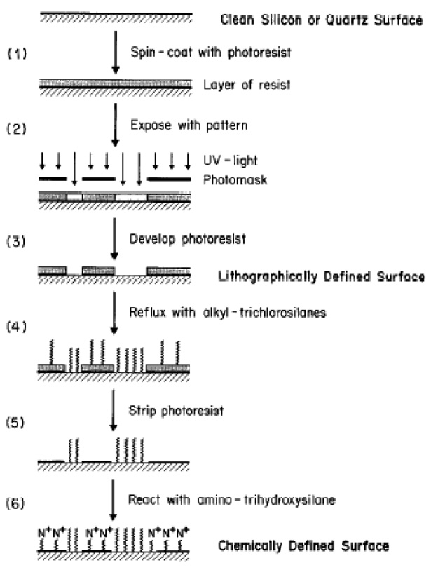
Photolithography was the first well established technique used in the patterning of SAMs in order to regulate cell growth and function. This method has produced patterns with dimensions down to a few microns. This technique involves three key components: a light source, a photoresist, and a photomask. The light source provides the energy required for the exposure of photoresist or ablation of a SAM over the selected regions of the substrate. Ultraviolet (UV) light has been the source most often used for patterning. Photoresist is a photo-sensitive material, typically made from organic compounds, whose molecular chains are capable of re-organizing or crosslinking upon exposure to energy. A photomask is a solid substrate (planar) usually made of quartz and coated with a thin layer (∼1 µm) of chrome with a desired geometrical pattern, which can be designed by CAD or AutoCAD programs. In the late 1980s, Kleinfield et al. first demonstrated that neurons can be spatially cultured on patterned SAMs, made of aminosilane and alkylsilane compounds (Kleinfeld, Kahler et al. 1988). A schematic of the processing steps involved in the chemical patterning of a silica glass substrate by conventional photolithography (photoresist-based) is shown in Fig. 5 (Kleinfeld, Kahler et al. 1988). The substrate used for patterning was first cleaned by covering with freshly prepared, suitable cleaning agents (such as H2O2 and H2SO4). The surface cleaned substrate was then subjected to spin-coating with the photoresist in a clean room facility (class 100 or class 1000), in order to avoid contamination by unwanted dust particles (Fig. 4, Step 1). The photoresist-coated substrate was exposed to UV light through the photomask (Fig. 4, Step 2). Note that the light rays were transmitted only through the quartz background, but not through the chrome pattern on the mask. This chemically alters the solubility of the photoresist in certain developer solutions due to the molecular chain re-arrangement. The light exposed part of the photoresist was then solubilized in a developer solution, which yielded a photoresist pattern that corresponds to the image of the pattern designed on the mask (Fig. 4, Step 3). Consequently, the material of interest (e.g., alkylchlorosilane, a cell inhibiting compound) to be patterned was applied on the photoresist pattern (Fig. 4, Step 4) and then the photoresist was carefully removed (Fig. 4, Step 5). The open areas (the area other than the cell inhibiting compound) were back-filled with another material of interest (e.g., alkylaminosilane, a cell promoting compound) (Fig. 4, Step 6). Finally, the chemically-defined substrate pattern made up of cell promoting and inhibiting compounds, or bi-phasic regions, was obtained.
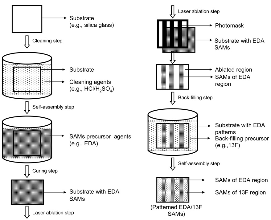
Fig. 5.
Schematic illustration of a pattern formation by deep UV photolithography.
Fig. 4.
Schematic of the processing steps involved in chemically patterning a silicon or slicon dioxide (quartz) substrate [Adapted with permission from Kleinfield, D., Katler, K. M., and Hockberger, P.E., Controlled outgrowth of dissociated neurons on patterned substrates, J. Neurosci. 8, 4098, 1988].
A method of direct ablation of SAMs was introduced, as a modified version of photolithography, without using a photoresist because the use of a photoresist in patterning led to many practical complications. For example, a small dust particle, or other form of ultra-fine debris, inhibits the uniformity of the thin layer of photoresist during spin-coating; thus, this step must be carried out in a clean room facility. Some biological solutions are banned from use in a clean room facility, which limits its usage in many biological applications. Apart from that, some chemicals that are used as a photoresist are toxic to cells, hence only a few organic compounds can be used as photoresist. All of these limitations severely curtails the use of a photoresist in biological applications. Direct laser ablation, also called deep UV photolithography, was introduced for patterning in the early 1990’s. A schematic of the pattern formation by deep UV photolithography is illustrated in Fig. 5. In the early 1990s, Dulcey et al. introduced the use of direct ablation by a deep UV light (193 nm) for pattering silane-based SAMs, without a photoresist (Dulcey, Georger et al. 1991). For this, monolayers of EDA were exposed to deep UV radiation, which was transmitted through the quartz mask, but not through the metal pattern (line-space design) on the mask, to induce photochemical changes in the cell adhesive EDA monolayers. The exposed substrates were then reacted with 13F to form hydrophobic regions that inhibited cell adhesion within the irradiated regions. On the patterned surfaces, the line denotes an EDA region and space denotes the 13F region. The patterned surfaces were used to spatially control the adhesion as well as direct the outgrowth of human nueroblastoma cells under in vitro conditions. The results indicted that cells had grown only on the EDA and not on the 13F regions, which has been a requisite for pattern formation. There was also evidence that EDA supported cell growth, while 13F inhibited cell growth. In addition, the results revealed that a large change occurred in the shape and growth of the cells cultured on the patterned surfaces with respect to their dimensional features. For instance, cells maintained a relatively spherical shape with visible contact points on a 40 µm wide EDA region, while on a low width (12 µm) EDA region cells were elongated and confined to the line. In this case the width of the line was smaller than the cell diameter and this greatly affected the shape and size of the cells. Based upon the experimental results, the authors suggested that the deep UV photolithographically-patterned SAMs was an interesting area of research and an enabling technology for manipulating molecular assemblies.
Patterned SAMs utilizing different aminosilanes have also been reported for use in neuronal studies. Stenger, D.A. et al., created DETA/13F patterned SAMs without utilizing a photoresist in order to determine their suitability to direct axonal and dendritic process extensions at single, hippocampal neuron level (Stenger, Hickman et al. 1998). First, SAMs of DETA were prepared on a glass coverslip, placed in contact with a photomask and then irradiated with a deep UV light (193 nm) using an Ar/F excimer laser customized with a beam homogenizer. The energy dosage was 8–15J/cm2, which was sufficient to ablate the amine groups, which yielded reactive hydroxyl groups. The photomasks used in this study were made from four different patterns over different dimensions. The irradiated surfaces (DETA-derivatized SAMs) were subsequently rederivatized with 13F, which resulted in a co-planar monolayer of permissive and non-permissive regions.
4.2 Cellular responses of photolithographycally-derived SAM patterns
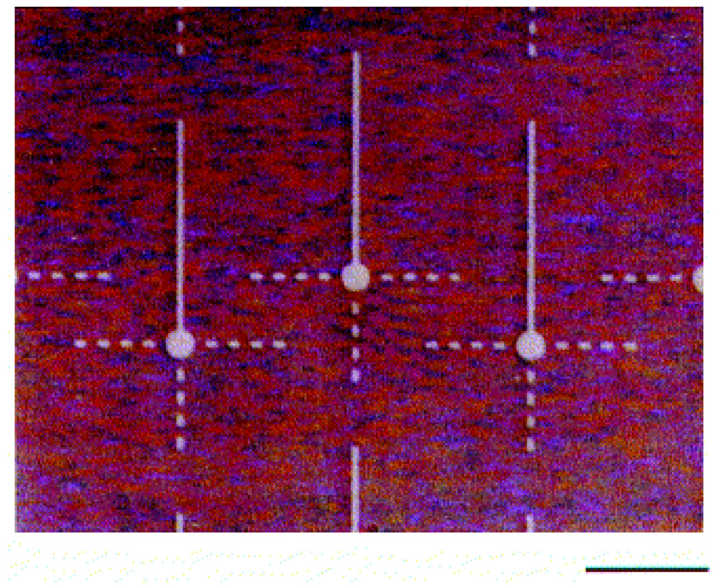
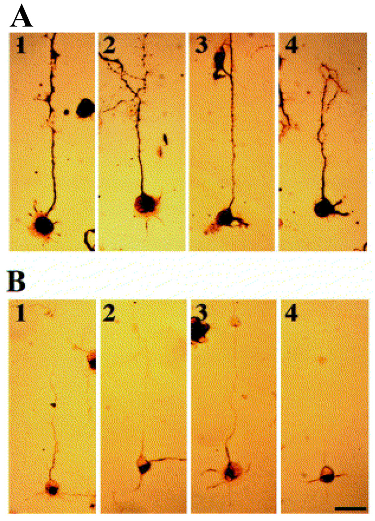
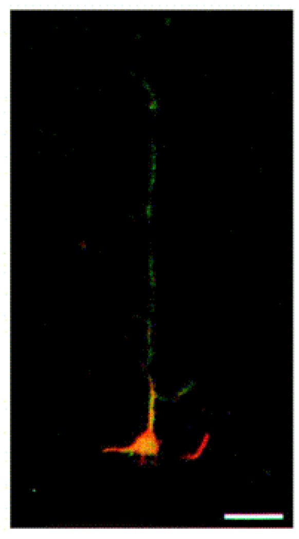
In this section, we briefly describe how the photolithographycally-derived SAM-patterns affected the physiology of neuronal cells in-vitro. An optical image of one of the above patterned substrates is shown in Figure 6, which shows a total intermittent pathlength of 80 µm, and is comprised of four DETA squares that are separated by 10 µm fluorinated silane (13F) called ‘speed bumps’ (Stenger, Hickman et al. 1998). The ability of the patterned system to control neuronal polarity at the single neuron level was evaluated in vitro, by using embryonic hippocampal cell cultures. To study the overall cellular processes, the cells on the patterned surfaces were stained using antibodies against MAP5 (microtubule associated proteins 5) and MAP2 (microtubule associated proteins 2) (see Fig. 7). In each case, the dominant process, cell body and multiple short processes are immunopositive for MAP5 (Fig. 7A), as expected for rapidly growing neuronal cultures, while MAP2 was more preferentially localized in the somatodendritic domains (Fig. 7B). To characterize the polarity of axonal and dendritic processes, at the single cell level, the cultured neuron was stained with antibodies to NF150 (neurofilament) (green) and MAP2 (red). Fig. 8 shows the double immunostaining of a representative hippocampal neuron after 4 days in culture, which illustrates the localization of NF150, but not MAP2, to the single dominant neurite that is consistent with its identification as the axon (Stenger, Hickman et al. 1998). In the case of the cells whose soma localized on the DETA nodes, approximately 76% of them had axons on the continuous DETA patterns, while dendrites were localized on lines with 13F speed pumps, that emenated from the central DETA node. These results suggested that geometrically-designed SAMs patterns had major impact on the neural polarity of in-vitro cultured hippocampal cells.
Fig. 6.
Differential interference contrast micrographs of DETA/13F patterned SAMs. Amine groups of DETA regions on the surface were labeled with Pd-Cl catalyst and metallized with nickel for visualization by optical microscopy. Somal adhesion sites had 25 µm diameters, DETA pathwidths were 5 µm, and the continuous pathway was 190 µm. The total intermittent pathlength was 80 µm, comprised of four 5 × 10 µm DETA squares separated by 10 µm 13F ‘speed bumps’; scale bar = 100 µm. [Adapted with permission from Stenger, D.A. et al., Microlithographic determination of axonal/dendrite polarity in cultured hippocampal neurons, J. Neurosci. Methods, 82, 167, 1998].
Fig. 7.
Immunocytochemical staining of neurons after 3 days in culture on a DETA/13F patterned substrate. Cells are stained using antibodies against MAP 5 (A) or MAP 2 (B). Scale bar = 50 µm [Adapted with permission from Stenger, D.A. et al., Microlithographic determination of axonal/dendrite polarity in cultured hippocampal neurons, J. Neurosci. Methods, 82, 167, 1998].
Fig. 8.
Double immunostaining of a representative hippocampal neuron after 4 days in culture on a DETA/13F patterned substrate. The neuron was stained with antibodies to NF150 (green) and MAP 2 (red) to illustrate the induced polarity of axonal and somatodendritic processes, respectively. Scale bar = 20 µm [Adapted with permission from Stenger, D.A. et al., Microlithographic determination of axonal/dendrite polarity in cultured hippocampal neurons, J. Neurosci. Methods, 82, 167, 1998].
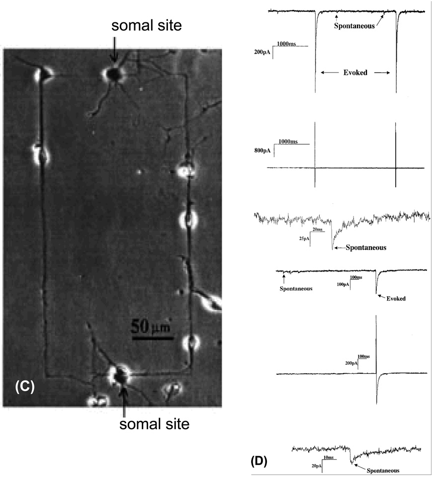
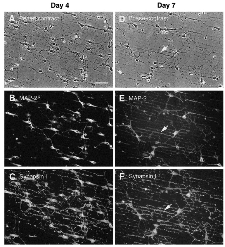
In another study, Ravenscroft et al. reported the patterning of the same DETA SAMs, but with different geometrical features in order to study neuronal synapse formation (Ravenscroft, Bateman et al. 1998). For this, circuit patterns were created using photolithography by exposing the DETA monolayer to ArF laser irradiation through a quartz mask composed of either a line space pattern or a circuit pattern. The exposure of the light degrades and partially removes the DETA regions according to the pattern of the mask. Next, a 13F monolayer was prepared on the laser irradiated substrate. The 13F molecules bind preferentially to the irradiated regions (regions without DETA), while negligible amounts of 13F binds to the un-irradiated regions (regions with DETA), yielding patterns that were then subsequently analyzed by imaging XPS (Ravenscroft, Bateman et al. 1998) . The patterned DETA/13F SAMs were evaluated for their ability to support neuronal cell behavior such as cell adhesion, survival, neurite outgrowth, and synapse formation using embryonic, hippocampal neuronal cells and compared to the unpatterned controls (9A). Cells, cultured on the patterned surface, only adhered to the DETA regions and not the 13F regions (Fig. 9B & C), which indicated that the DETA strongly supported cell adhesion and growth while the 13F inhibited the cell growth. There was a high degree of compliance in the neural soma and processes (dendrites, for example). Cells that were cultured on the unpatterned surface (i.e. DETA SAMs) grew at random (Fig. 9A), indicating that the patterning process dictated the cell orientation and contact guidance. Since synapse formation is a critical prerequisite in the development of functional neuronal networks the authors carried out electrophysiological studies in order to assess the functional synaptic connectivity in the neuronal networks by measuring spontaneous and evoked postsynaptic currents using the dual patch-clamp technique (Fig. 9D). The results obtained from the electrophysiological recordings of the neurons cultured on the patterned surfaces noted the appearance of either spontaneous or evoked postsynaptic currents, which was clear evidence in the support of neuronal differentiation and functional synapse formation on both types of patterns. In a later study (Ma, Liu et al. 1998) line space patterned surfaces were stained with antibodies to synapsin I and MAP-2. The results indicated that DETA surfaces promoted neuronal synapse formation, whereas evidence for synapse formation on 13F surfaces was barely detected. It was also observed, as noted in Fig. 10, that MAP-2 neuronal soma (cell body) and dendrites were co-localized with synapsin I puncta, along the DETA regions (line space patterns). All these experimental examples demonstrate the suitability of patterned silane surfaces for controlling neuronal function and organizing synapse formation in-vitro.
Fig. 9.
Electrophysiological characterization of hippocampal cells patterned on DETA lines and circuit patterns. (A & B) Phase-contrast photomicrographs showing two day old cultures of cells dissociated from embryonic, day 19, rat hippocampal neurons and plated in serum-free medium on a homogeneous DETA (A) or a patterned surfaces consisting of parallel lines (DETA) and spaces (13F) (B). The patterns consist of thin DETA lines that are interrupted by 13F spaces. The DETA film was exposed to deep UV light through a photo-mask that contained a pattern of parallel chrome lines. Irradiated DETA was photocleaved and 13F was then bound to the irradiated areas. (C) Hippocampal cells culture plated onto a circuit pattern utilizing DETA lines in a field of 13F for the RT12 mask feature. Cell bodies adhered to DETA lines along which processes also grew. (D). Electrophysiology data showing the current response for day 12 in Vitro hippocampal neurons displaying both spontaneous and evoked activity on (top half) an unpatterned DETA-modified surface and (bottom half) a DETA/15F line-space patterned surface. In both cases, the top trace represents the current response of the post-synaptic neuron, the middle trace represents the stimulation current applied to the pre-synaptic neuron, and the bottom trace represents an enlargement of a spontaneous current signal from the top trace (post-synaptic neuron). [Adapted with permission from Ravenscroft, et al.]
Fig. 10.
Distribution of synapsin I and MAP-2 in hippocampal neurons on DETA/13F patterned substrates. The photomicrographs aligned in each column are from three exposures of a single field of cells. Phase-contrast (A and D) and fluorescence photomicrographs illustrating double-immunostaining for synapsin I and MAP-2 in 4- (A–C) and 7- (D–F) day-old hippocampal cultures. Approximately two thirds of the cells are MAP-2+, which is evident in the cell bodies and dendrites, but absent from axons. Arrowheads in D, E and F point to fluorescent puncta of synapsin I immunoreactivity, which are outlining MAP-2+ dendrites primarily located along DETA lines. Scale bar = 100 µm [Adapted with permission from Ma, W. et al., Central neuronal synapse formation on micropatterned surfaces, Develop. Brain Res, 111, 231, 1998].
Although both of the conventional photolithographic techniques are utilized for the production of complex and accurate pattern networks with high resolution, they have certain disadvantages which hinder their wider application. For example, the photoresist-based photolithography technique can only be applied to pattern certain materials that are photosensitive and most of the chemicals utilized in this technique are either toxic or incompatible to cells and other biomolecules. This technique typically requires expensive instrumentation as well as clean-room facilities for the production of the photomask and spin-coating of the photoresist, which are essential for patterning, therefore this technique is more expensive to employ. On the other hand, while deep UV photolithography eliminates the use of the photoresist, it still requires all the expensive instrumentation and clean-room facilities for the photomask. In addition, both of these techniques can be applied only for the patterning of planar surfaces as they are poorly suited for 3D substrates. In addition, direct functionalization with certain biological substances (proteins and ligands, for example) has not been highly developed using these techniques, because it typically requires specific crosslinkers to directly pattern the biomolecules. These limitations stimulated the development of new fabrication techniques for the patterning of biologically-active materials. In the study by Singhvi et al. (1994), an alternative technique called soft lithography was reported for patterning SAMs of alkanethiolates onto a gold surface for engineering cell shape and size (Singhvi, Kumar et al. 1994). The name ‘soft lithography’ was coined because one of the key components of this technique called ‘stamp’ is made from a ‘soft’ elastomeric material. This technique has been highly suitable for biomedical (tissue engineering, for example) and biotechnological (cellular biosensors, for example) applications because it was possible to place cells or proteins into specific locations on the scaffolding material or chip substrates in order to control their shape, growth and function. However, production of high resolution patterns using this technique has been limited compared to photolithography. The details of this methodology and the processing steps involved in this technique are described in the following sections with experimental examples.
4.3 Patterning by microcontact printing
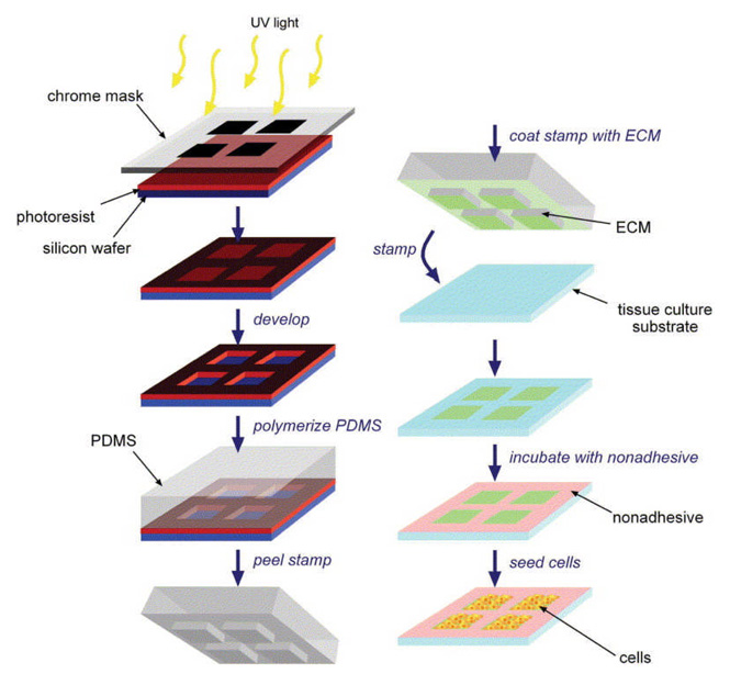
Microcontact printing (µCP) has become a popular technique because of its simplicity, flexibility and ability to pattern many biomaterials, in particular tissue-culture substrates, with feature-sizes down to 1 µm in the form of SAMs without using expensive equipment and special facilities (class 100 or class 1000 laboratories, for example) after the creation of the master stamp. In addition, and more importantly, this versatile technique can be extended to pattern non-planar surfaces (3D assembly), unlike conventional photolithography methods where it is not generally feasible. Moreover, the patterned material doesn’t have to be photosensitive. This technique enables researchers to pattern SAMs from both biological and non-biological substances. This technique was initially developed by George M. Whitesides and his group and it was introduced to pattern SAMs of alkanethiolates onto a gold surface in order to control cell behavior and for engineering cell shape and function by modulating the surface characteristics (Singhvi, Kumar et al. 1994). Figure 11 shows a schematic of the major processing steps involved in the pattern formation by using µCP (Liu and Chen 2005). This method has been based on the utilization of an elastomeric stamp to print a pattern of the material of interest (ECM proteins, for example) on a solid substrate with the help of molecular self-assembly. There are three major components associated with this technique, namely master, stamp, and ink. The ‘master’ is a solid material (silicon, for example), often created by standard photolithography with a desired geometry with high resolution features that are specific to that application. The ‘stamp’ is a soft elastomeric material, frequently created by casting an elastomeric material (for example: polydimethylsiloxane (PDMS), (H3C)(SiO(CH3)2)nSi(CH3)3,) over a pre-designed master. The ‘ink’ is a functional material chosen to be patterned onto the substrate material. In the patterning process, the stamp is first inked with a solution made from the material of interest and the stamp is then brought into contact with the surface of the substrate material. For a period of time, the stamp and the substrate remain undisturbed, which ultimately yields a geometrical pattern of the stamp on the substrate material. Note: prior to µCP, the stamp is subjected to an oxygen plasma treatment in order to oxidize the outer surface of the stamp as this facilitates surface hydrophilization that could eventually assist the adsorption of the ink to the stamp’s surface. A result of the stamping process is the formation of a SAM on the substrate’s surface, in those regions where the stamp has come into contact with the substrate. The sizes of the features stamped have ranged from hundreds of microns to a few micrometers. The unstamped regions are then backfilled with another material of interest (non cell-adhesive compounds, for example) in order to ensure that the cells have grown only on the cell adhesive regions of the SAM, although some applications just leave the gold bare as the negative surface. This way, the substrate could be imprinted with multiple SAM surfaces. The resultant patterned surface can be used to study the fundamental aspects of cell behaviors in both small- and large-scale cell cultures. This technique may also be useful for the fabrication of sheets of cells in defined patterns and shapes for use in tissue engineering.
Fig. 11.
Schematic of the micropatterning process. PDMS stamps are generated by photolithography (left column) and, using these stamps, ECM proteins are printed onto tissue-culture substrates upon which cells are seeded (right column) [Adapted with permission from Wendy, F.L. and Christopher, S.C., Engineering biomaterials to control cell function, Materials Today, 8, 28, 2005].
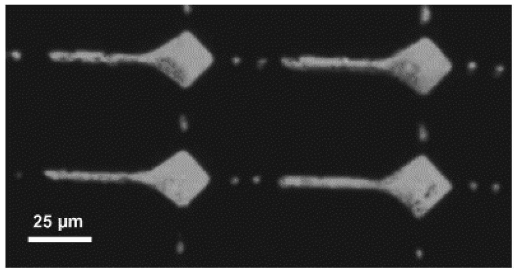
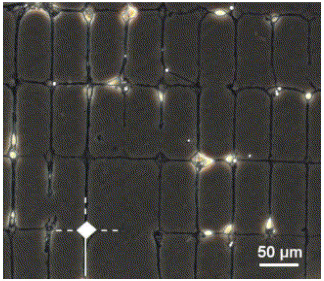
Recently, SAM-patterning methods based on protein components have been developed for use in cellular engineering. Cells, in general, have the ability to sense and respond to their surrounding microenvironments. These microenvironments contain several adhesive or signaling proteins, which are essential for cell attachment, growth and subsequent functions. The attachment of cells to the proteins is primarily mediated by specific interactions that occur between the integrin receptors of the cellular membranes and a short peptide sequence of the proteins. Since proteins play a key role in driving certain cellular behaviors, the concept of patterning SAMs from proteins to control cell growth and functions has been introduced. There are many proteins that encourage cell adhesion (fibronectin, for example), while some discourage cell attachment (albumin, for example). Recently, Vogt et al. demonstrated the impact of micropatterned protein surfaces, made by µCP, on neuronal polarity determination (Vogt, Stefani et al. 2004). The authors created a similar type of patterned surfaces as reported by Stenger et al. (Stenger, Hickman et al. 1998), that contained continuous and interrupted pathways (lines), but using different patterning techniques and surface chemistry. Note: there are three major differences in this system compared to the system created by Stenger et al. (1998): (i) Cells, this study used cortical cells rather than hippocampal, (ii) Patterning method, the patterned SAMs were created by µCP rather than deep UV photolithography, and (iii) Surface chemistry, this study used a blend of ECM proteins and poly-D-lysine on a background of a polystyrene surface instead of DETA on a 13F background for the patterns. The authors created a patterned substrate by using the µCP technique and the polystyrene substrate was modified with ECM proteins in combination with poly-D-lysine. The pattern’s geometry has two distinct line pathways as shown in Fig. 12 (Vogt, Stefani et al. 2004). The reason for the creation of two different pathways was that the neurite extension would be faster on the solid line, which represented a continuous adhesive pathway, than on the interrupted lines. Consequently, the axonal extension should preferably occur along the solid line, while dendrites should grow on the interrupted lines as shown by Stenger et al. (1998).
Fig. 12.
Optical micrograph of well-defined protein patterns against an uncoated polystyrene background. The picture was taken after stamping with an inking solution containing the fluorescent dye sulforhodamine to allow visualization [Adapted with permission from Vogt, A.K. et al., Impact of micropatterned surfaces on neuronal polarity, J. Neurosci. Methods, 134, 191, 2004].
Here we briefly describe their methodology for the fabrication of patterned surfaces using µCP and their impact on neuronal polarity. First, they created the master by a standard photolithographic technique. A PDMS stamp was then fabricated by curing Sylgard 184 in 2 ml eppendorf tubes that were inverted on the master for 48 h at 55 °C with a final curing at 110 °C for 1 h. The stamp was stored in deionized water for 24 h prior to use, and then decontaminated in a 70% ethanol for 1 min. The ‘inking’ solution was made by mixing a 1:100 dilution of ECM-gel in Dulbecco’s modified eagle’s medium containing 10 µg/ml poly-D-lysine. The stamp was then inked with a solution of ECM mixture for 30 sec and dried in a stream of nitrogen. After inking, the stamp was gently placed on the polystyrene substrate, pressed by hand for 10 sec, to ensure adequate contact between the stamp and substrate, and then carefully removed from the substrate. All patterned structures had meshes of 50 µm × 100 µm with somal adhesion sites of 22 µm in diameter and lines of 4 µm in width (See Fig. 12). One line emerging from a somal adhesion node was always continuous (for axonal outgrowth), while three were interrupted (for dendritic outgrowth). Three types of patterns with different size gaps were used on the interrupted lines. These patterns were evaluated for their suitability to support cortical neuronal cultures and their effect on the cellular polarity with respect to the magnitude of the patterned surfaces.
4.4 Cellular responses of µCP-derived SAMs patterns
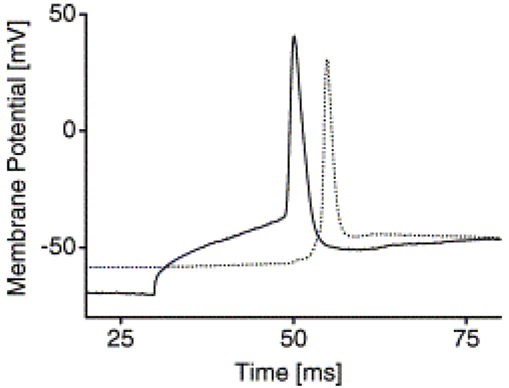
In this section, we briefly describe how neuronal cells are responding to photolithographycally-derived patterns of SAMs in the cellular environment in-vitro. An optical image of cortical neurons cultured on the patterned surface is shown in Figure 13 (Vogt, Stefani et al. 2004). As seen in the figure, cell bodies adhered to the node points of the pattern with high fidelity, while neurite extensions occurred along both line types. After several days in culture, the formation of geometrically defined networks could be observed. This was similarly noted on the uninterrupted patterns. As the highlight of this study, the results showed that the neuron extended two processes onto the grid lines; the major one (presumably the axon) was clearly directed along the interrupted line path, while a shorter one (presumably the dendrite) followed the permissive line path, which indicated that in the presence of ECM proteins adhesiveness alone does not appear to control the speed of the neurite outgrowth as indicated by Stenger et al., (Stenger, Hickman et al. 1998) for a SAM only system. The authors have also investigated the orientation of the axons and dendrites in the patterned network through a double patch clamp measurement (current clamp mode). For this, action potentials were evoked in one cell at a time, while the effect on the other cell was monitored without applying stimuli. A typical recording of two synaptically coupled cells is shown in Fig. 14 (the solid line denotes the stimulated cell and the dotted line denotes the unstimulated cell). This shows evidence for synapse formation. The authors suggested that another promising approach for the determination of neuronal polarity may lie in the creation of a desired pattern in which two chemically different permissive pathways emerge from each adhesion node as first indicated by Snow and Letourneau (Snow and Letourneau 1992). This kind of patterned system may also have potential in designing artificial, neuronal cell networks in order to study dissociated cell development and long-term network architecture plasticity.
Fig. 13.
Optical micrograph showing a network of cortical neurons grown on a protein pattern on day 12 [Adapted with permission from Vogt, A.K. et al., Impact of micropatterned surfaces on neuronal polarity, J. Neurosci. Methods, 134, 191, 2004].
Fig. 14.
Double patch clamp measurements for the detection of synapses. An action potential was elicited through a depolarizing current pulse in one cell while the effect on the other cell was monitored without applying a stimulus. In this example, the postsynaptic potential was large enough to trigger a postsynaptic action potential (solid line: stimulated cell, dotted line: unstimulated cell) [Adapted with permission from Vogt, A.K. et al., Impact of micropatterned surfaces on neuronal polarity, J. Neurosci. Methods, 134, 191, 2004].
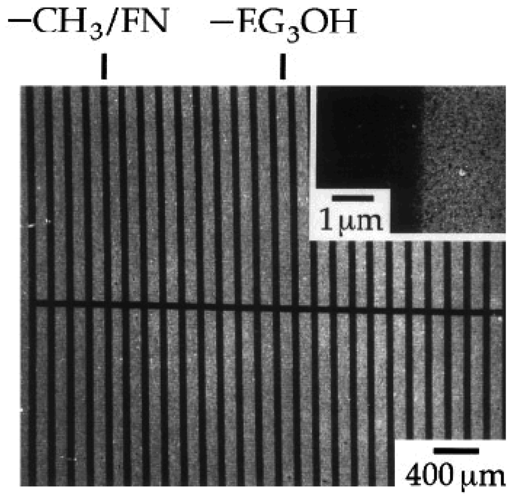
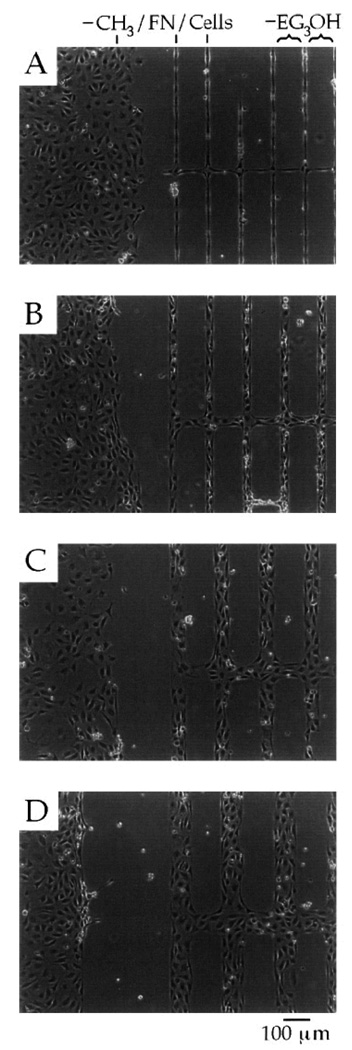
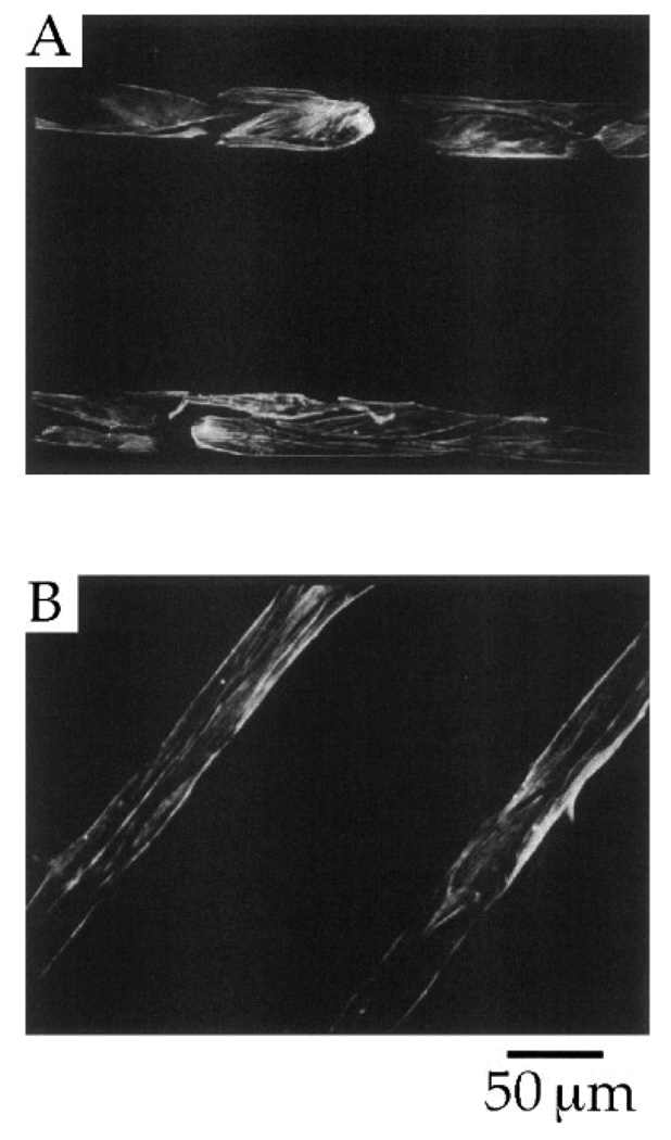
A strategy based on the combination of cell adhesive and non-adhesive protein-based SAMs provides a remarkably good pattern system with excellent control over surface properties that are required for spatial distribution of the cells. In an interesting study, Mrksich et al. (1997) reported that µCP of SAMs of fibronectin, a cell adhesive ECM protein, was suitable for patterning endothelial cells (Mrksich, Dike et al. 1997) as shown initially by Spargo et al (1994) utilizing deep UV lithography of SAMs (Spargo, Testoff et al. 1994). To achieve this, the authors first patterned SAMs of two different alkanethiolates, one with a methyl (CH3) group that promoted protein adsorption, while another with an oligo(ethylene glycol) (EG3OH) group resisted protein adsorption on a gold surface, and then coated with fibronectin on selected regions (see Fig. 15). This method provides a simple way to either promote or resist protein adsorption and, thus, promote or inhibit cell adhesion on the patterned surface. The SAM patterns had methyl-terminated lines with widths of 10, 30, 60 and 90 µm and each line was separated by oligo(ethylene glycol)-terminated regions of 120 µm in width. Notice that the protein adsorbed preferably to the methyl-terminated pattern regions, not on the oligo(ethylene glycol)-terminated regions. The efficacy of these patterns in promoting spatial cell growth was evaluated using bovine capillary endothelial cells. The results showed that the cells preferred to grow only on the regions coated with fibronectin, while in the rest of the regions (i.e., uncoated with fibronectin) the cells did not grow well (see Fig. 16) (Mrksich, Dike et al. 1997). The cultured cells on the patterns were stained for actin microfilaments using fluorescein-labeled phalloidin in order to study cytoskeleton development. Figure 17 shows the florescent immunostaining of the actin microfilaments of the bovine capillary endothelial cells attached to the patterned SAMs having lines with 30 µm width. The microfilaments, after 24 h in culture, displayed an organization typical of nonpatterned cells, although the filaments were aligned at the edges of the patterned regions. However, after 72 h, the microfilaments were uniformly aligned with the underlying pattern, which was a good indication of cellular alignment and orientation. This study also indicated that ECM protein adsorption was an appropriate choice for the proper control of cell position and growth behaviors. Overall, these examples demonstrated that the patterning process greatly influenced the behavior of the cells including their orientation and localization. Thus, the patterned surfaces can be used to localize cells within a specified area of interest in order to enable spatial growth as well as to control their function.
Fig. 15.
Scanning electron micrograph of fibronectin (FN) adsorbed to a patterned SAMs of alkylthiolates on a gold surface. The layer of protein attenuates a secondary electron emission and appears as the dark areas in the micrograph. The inset shows a view at a higher magnification and demonstrates the edge resolution of the protein pattern [Adapted with permission from Mrkish, M. et al., Using microcontact printing to pattern the attachment of mammalian cells to self-assembled monolayers of alkanethiolates on transparent films of gold and silver, Exp. Cell Res. 235, 305, 1997].
Fig. 16.
Optical micrographs of cells attached (after 49 h) to a patterned SAMs of alkylthiolates on a gold surface having unpatterned regions terminated in methyl groups (left) and patterned lines (right) with sizes of 10 (A), 30 (B), 60 (C), and 90 (D) µm in width. Notice that surface regions that are modified with SAMs present an oligo(ethylene glycol) resistance to the adsorption of protein (fibronectin) and, thus, subsequent attachment of cells [Adapted with permission from Mrkish, M. et al., Using microcontact printing to pattern the attachment of mammalian cells to self-assembled monolayers of alkanethiolates on transparent films of gold and silver, Exp. Cell Res. 235, 305, 1997].
Fig. 17.
Florescent immunostaining of the actin microfilaments of bovine capillary endothelial cells attached to patterned SAMs of alkylthiolates on a gold surface having lines with a width of 30 µm. Individual cells are evident after a period of 24 h (A) and after 72 h (B), the actin cytoskeletons of adjacent cells align [Adapted with permission from Mrkish, M. et al., Using microcontact printing to pattern the attachment of mammalian cells to self-assembled monolayers of alkanethiolates on transparent films of gold and silver, Exp. Cell Res. 235, 305, 1997].
5. Concluding remarks
Design strategies and methodologies of surface modification of biomaterials that are suitable to control cell behavior are discussed in this article, in the context of cell patterning. The experimental examples summarized represent some of the applications of SAMs based on a variety of approaches, conventional to non-conventional. The results of all these experimental examples, together with other studies, clearly demonstrate the efficacy of the SAM-patterned biomaterials to regulate cell growth and function. The patterning of SAMs continues to be an interesting and emerging area of applied research and an enabling technology for manipulating cellular assemblies in a controlled fashion. Therefore, patterning cells on biomaterial surfaces will be of great use in various medical-related applications, in particular cell-based biosensors and scaffold-based tissue engineering. In contrast to in vivo approaches, numerous investigations focused on in vitro cell engineering, because at present, there is very limited information available in the literature on in vivo cell engineering. This is an exciting time to be involved in surface patterning of biomaterials, both at micro- and nano-scale dimensions, in order to develop them as a promising synthetic ECM for in vitro cell engineering, with great challenges and also with great expectations ahead.
Acknowledgements
The authors wish to acknowledge the NanoScience Technology Center, University of Central Florida, for financial support as well as NIH grant number 5 RO1NS050452-03 and DOE grant number DE-FG02-04ER46171.
References
- Andersson AS, Olsson P, Lidberg U, Sutherland D. The effects of continuous and discontinuous groove edges on cell shape and alignment. Experimental Cell Research. 2003;288:177–188. doi: 10.1016/s0014-4827(03)00159-9. [DOI] [PubMed] [Google Scholar]
- Arnesen S, Mosler S, Larsen NB, Gadegaard N, Purslow PP, Lawson MA. The effects of collagen type I topography on myoblasts in vitro. Connective Tissue Research. 2004;45:238–247. doi: 10.1080/03008200490888424. [DOI] [PubMed] [Google Scholar]
- Bigelow WC, Pickett DL, Zisman WA. Oleophobic Monolayers. I. Films adsorbed from solution in non-polar liquids. J. Colloid Interface Sci. 1946;1:513. [Google Scholar]
- Craighead HG, James CD, A. Turner MP. Chemical and topographical patterning for directed cell attachment. Current Opinion in Solid State & Materials Science. 2001;5:177–184. [Google Scholar]
- Curtis A, Wilkinson C. Topographical control of cells. Biomaterials. 1997;18:1573–1583. doi: 10.1016/s0142-9612(97)00144-0. [DOI] [PubMed] [Google Scholar]
- Dalby MJ, Childs S, Riehle MO, Johnstone HJH, Affrossman S, Curtis ASG. Fibroblast reaction to island topography: changes in cytoskeleton and morphology with time. Biomaterials. 2003;24:927–935. doi: 10.1016/s0142-9612(02)00427-1. [DOI] [PubMed] [Google Scholar]
- Dalby MJ, Giannaras D, Riehle MO, Gadegaard N, Affrossman S, Curtis ASG. Rapid fibroblast adhesion to 27 nm high polymer demixed nano-topography. Biomaterials. 2004;25:77–83. doi: 10.1016/s0142-9612(03)00475-7. [DOI] [PubMed] [Google Scholar]
- Dalby MJ, Riehle MO, Johnstone H, Affrossman S, Curtis ASG. In vitro reaction of endothelial cells to polymer demixed nanotopography. Biomaterials. 2002;(23):2945–2954. doi: 10.1016/s0142-9612(01)00424-0. [DOI] [PubMed] [Google Scholar]
- Dalby MJ, Riehle MO, Johnstone HJH, Affrossman S, Curtis ASG. Polymer-demixed nanotopography: Control of fibroblast spreading and proliferation. Tissue Engineering. 2002;8:1099–1108. doi: 10.1089/107632702320934191. [DOI] [PubMed] [Google Scholar]
- Desai TA. Micro- and nanoscale structures for tissue engineering constructs. Medical Engineering & Physics. 2000;22:595–606. doi: 10.1016/s1350-4533(00)00087-4. [DOI] [PubMed] [Google Scholar]
- Du YZ, Wood LL, Saavedra SS. Growth behavior and structure of alkyltrichlorosilane monolayers bearing thioacetate and acetate tailgroups. Materials Science & Engineering C-Biomimetic and Supramolecular Systems. 2000;7:161–169. [Google Scholar]
- Dulcey CS, J. Georger JH, Krauthamer V, Stenger DA, Fare TL, Calvert JM. Deep UV photochemistry of chemisorbed monolayers: patterned coplanar molecular assemblies. Science. 1991;252:551–554. doi: 10.1126/science.2020853. [DOI] [PubMed] [Google Scholar]
- Dvir T, Tsur-Gang O, Cohen S. Designer scaffolds for tissue engineering and regeneration. Israel Journal of Chemistry. 2005;45:487–494. [Google Scholar]
- Falconnet D, Csucs G, Grandin HM, Textor M. Surface engineering approaches to micropattern surfaces for cell-based assays. Biomaterials. 2006;27:3044–3063. doi: 10.1016/j.biomaterials.2005.12.024. [DOI] [PubMed] [Google Scholar]
- Ferguson GS, Chaudhury MK, Biebuyck HA, Whitesides GM. Monolayers on Disordered Substrates - Self-Assembly of Alkyltrichlorosilanes on Surface-Modified Polyethylene and Poly(Dimethylsiloxane) Macromolecules. 1993;26:5870–5875. [Google Scholar]
- Flemming RG, Murphy CJ, Abrams GA, Goodman SL, Nealey PF. Effects of synthetic micro- and nano-structured surfaces on cell behavior. Biomaterials. 1999;20:573–588. doi: 10.1016/s0142-9612(98)00209-9. [DOI] [PubMed] [Google Scholar]
- Geissler M, Xia Y. Patterning: Principles and Some New Developments. Advanced Materials. 2004;16:1249–1269. [Google Scholar]
- Georger JH, Stenger DA, Rudolph AS, Hickman JJ, Dulcey CS, Fare TL. Coplanar Patterns of Self-Assembled Monolayers for Selective Cell-Adhesion and Outgrowth. Thin Solid Films. 1992;210:716–719. [Google Scholar]
- Grayson ACR, Shawgo RS, Johnson AM, Flynn NT, Li YW, Cima MJ, Langer R. A BioMEMS review: MEMS technology for physiologically integrated devices; Proceedings Of The Ieee; 2004. [Google Scholar]
- Hickman JJ, Bhatia SK, Quong JN, Shoen P, Stenger DA, Pike CJ, Cotman CW. Rational Pattern Design for in-Vitro Cellular Networks Using Surface Photochemistry. Journal of Vacuum Science & Technology a-Vacuum Surfaces and Films. 1994;12:607–616. [Google Scholar]
- Hickman JJ, Ofer D, Laibinis PE, Whitesides GM, Wrighton MS. Molecular self-assembly of two-terminal, voltammetric microsensors with internal references. Science. 1991;252:688–691. doi: 10.1126/science.252.5006.688. [DOI] [PubMed] [Google Scholar]
- Hickman JJ, Ofer D, Zou C, Wrighton MS, Laibinis PE, Whitesides GM. Selective functionalization of gold microstructures with ferrocenyl derivatives via reaction with thiols or disulfides: Characterization by electrochemistry and auger electron spectroscopy. Journal of the American Chemical Society. 1991;113:1128–1132. [Google Scholar]
- Ito Y. Surface micropatterning to regulate cell functions. Biomaterials. 1999;20:2333–2342. doi: 10.1016/s0142-9612(99)00162-3. [DOI] [PubMed] [Google Scholar]
- Jenney CR, Anderson JM. Alkylsilane-modified surfaces: Inhibition of human macrophage adhesion and foreign body giant cell formation. Journal Of Biomedical Materials Research. 1999;46:11–21. doi: 10.1002/(sici)1097-4636(199907)46:1<11::aid-jbm2>3.0.co;2-y. [DOI] [PubMed] [Google Scholar]
- Jung DR, Kapur R, Adams T, Giuliano KA, Mrksich M, Craighead HG, Taylor DL. Topographical and physicochemical modification of material surface to enable patterning of living cells. Critical Reviews in Biotechnology. 2001;21:111–154. doi: 10.1080/20013891081700. [DOI] [PubMed] [Google Scholar]
- Kaehr B, Allen R, Javier DJ, Currie J, Shear JB. Guiding neuronal development with in situ microfabrication. Proceedings of The National Academy of Sciences of The United States of America. 2004 doi: 10.1073/pnas.0407204101. [DOI] [PMC free article] [PubMed] [Google Scholar]
- Khademhosseini A, Langer R, Borenstein J, Vacanti JP. Microscale technologies for tissue engineering and biology. Proceedings of the National Academy of Sciences of the United States of America. 2006 doi: 10.1073/pnas.0507681102. [DOI] [PMC free article] [PubMed] [Google Scholar]
- Kleinfeld D, Kahler KH, Hockberger PE. Controlled outgrowth of dissociated neurons on patterned substrates. J Neurosci. 1988;8:4098–4120. doi: 10.1523/JNEUROSCI.08-11-04098.1988. [DOI] [PMC free article] [PubMed] [Google Scholar]
- Kumar G, Wang YC, Co C, Ho CC. Spatially controlled cell engineering on biomaterials using polyelectrolytes. Langmuir. 2003;19:10550–10556. [Google Scholar]
- Laibinis PE, Hickman JJ, Wrighton MS, Whitesides GM. Orthogonal self-assembled monolayers: Alkanethiols on gold and alkane carboxylic acids on alumina. Science. 1989;245:845–847. doi: 10.1126/science.245.4920.845. [DOI] [PubMed] [Google Scholar]
- Li N, Folch A. Integration of topographical and biochemical cues by axons during growth on microfabricated 3-D substrates. Experimental Cell Research. 2005;311:307–316. doi: 10.1016/j.yexcr.2005.10.007. [DOI] [PMC free article] [PubMed] [Google Scholar]
- Liu WF, Chen CS. Engineering biomaterials to control cell function. Materials Today. 2005;8:28–35. [Google Scholar]
- Ma W, Liu QY, Jung D, Manos P, Pancrazio JJ, Schaffner AE, Barker JL, Stenger DA. Central neuronal synapse formation on micropatterned surfaces. Developmental Brain Research. 1998;111:231–243. doi: 10.1016/s0165-3806(98)00142-4. [DOI] [PubMed] [Google Scholar]
- Molnar P, Hirsch-Kuchma M, Rumsey JW, Wilson K, Hickman JJ. Biosurface engineering. In: Webster JG, editor. Encyclopedia of Medical Devices and Instrumentation. New York: John Wiley & Sons, Inc; 2006. pp. 409–417. [Google Scholar]
- Mrksich M, Dike LE, Tien J, Ingber DE, Whitesides GM. Using microcontact printing to pattern the attachment of mammalian cells to self-assembled monolayers of alkanethiolates on transparent films of gold and silver. Experimental Cell Research. 1997;235:305–313. doi: 10.1006/excr.1997.3668. [DOI] [PubMed] [Google Scholar]
- Mrksich M, Whitesides GM. Patterning Self-Assembled Monolayers Using Microcontact Printing - a New Technology for Biosensors. Trends in Biotechnology. 1995;13:228–235. [Google Scholar]
- Mrksich M, Whitesides GM. Using self-assembled monolayers to understand the interactions of man-made surfaces with proteins and cells. Annual Review of Biophysics and Biomolecular Structure. 1996;25:55–78. doi: 10.1146/annurev.bb.25.060196.000415. [DOI] [PubMed] [Google Scholar]
- Nuzzo RG, Allara DL. Adsorption of Bifunctional Organic Disulfides on Gold Surfaces. Journal of the American Chemical Society. 1983;105:4418. [Google Scholar]
- Oliva AA, James CD, Kingman CE, Craighead HG, Banker GA. Patterning axonal guidance molecules using a novel strategy for microcontact printing. Neurochemical Research. 2003;28:1639–1648. doi: 10.1023/a:1026052820129. [DOI] [PubMed] [Google Scholar]
- Ostuni E, Yan L, Whitesides GM. The interaction of proteins and cells with self-assembled monolayers of alkanethiolates on gold and silver. Colloids and Surfaces B-Biointerfaces. 1999;15:3–30. [Google Scholar]
- Parikh AN, Allara DL, Azouz IB, Rondelez F. An Intrinsic Relationship between Molecular-Structure in Self- Assembled N-Alkylsiloxane Monolayers and Deposition Temperature. Journal of Physical Chemistry. 1994;98:7577–7590. [Google Scholar]
- Ratner BD, Bryant SJ. Biomaterials: Where we have been and where we are going. Annual Review of Biomedical Engineering. 2004;6:41–75. doi: 10.1146/annurev.bioeng.6.040803.140027. [DOI] [PubMed] [Google Scholar]
- Ravenscroft MS, Bateman KE, Shaffer KM, Schessler HM, Jung DR, Schneider TW, Montgometry CB, Custer TL, Schaffner AE, Liu QY, Li YX, Barker JL, Hickman JJ. Developmental neurobiology implications from fabrication and analysis of hippocampal neuronal networks on patterned silane-modified surfaces. Journal of the American Chemical Society. 1998;120:12169–12177. [Google Scholar]
- Romanova EV, Fosser KA, Rubakhin SS, Nuzzo RG, Sweedler JV. Engineering the morphology and electrophysiological parameters of cultured neurons by microfluidic surface patterning. FASEB J. 2004;03:1368fje. doi: 10.1096/fj.03-1368fje. [DOI] [PubMed] [Google Scholar]
- Saneinejad S, Shoichet MS. Patterned poly(chlorotrifluoroethylene) guides primary nerve cell adhesion and neurite outgrowth. Journal of Biomedical Materials Research. 2000;50:465–474. doi: 10.1002/(sici)1097-4636(20000615)50:4<465::aid-jbm1>3.0.co;2-k. [DOI] [PubMed] [Google Scholar]
- Sanjana NE, Fuller SB. A fast flexible ink-jet printing method for patterning dissociated neurons in culture. Journal of Neuroscience Methods. 2004;136:151–163. doi: 10.1016/j.jneumeth.2004.01.011. [DOI] [PubMed] [Google Scholar]
- Schaffner AE, Barker JL, Stenger DA, Hickman JJ. Investigation of the factors necessary for growth of hippocampal neurons in a defined system. Journal of Neuroscience Methods. 1995;62:111–119. doi: 10.1016/0165-0270(95)00063-1. [DOI] [PubMed] [Google Scholar]
- Schlenoff JB, Li M, Ly H. Stability and self-exchange in alkanethiol monolayers. Journal of the American Chemical Society. 1995;117:12528–12536. [Google Scholar]
- Senaratne W, Andruzzi L, Ober CK. Self-assembled monolayers and polymer brushes in biotechnology: Current applications and future perspectives. Biomacromolecules. 2005;6:2427–2448. doi: 10.1021/bm050180a. [DOI] [PubMed] [Google Scholar]
- Singhvi R, Kumar A, Lopez GP, Stephanopoulos GN, Wang DI, Whitesides GM, Ingber DE. Engineering cell shape and function. Science. 1994;264:696–698. doi: 10.1126/science.8171320. [DOI] [PubMed] [Google Scholar]
- Smith RK, Lewis PA, Weiss PS. Patterning self-assembled monolayers. Progress In Surface Science. 2004;75:1–68. [Google Scholar]
- Snow DM, Letourneau PC. Neurite outgrowth on a step gradient of chondroitin sulfate proteoglycan (CSPG) Journal of Neurobiology. 1992;23:322–336. doi: 10.1002/neu.480230311. [DOI] [PubMed] [Google Scholar]
- Spargo BJ, Testoff MA, Nielsen TB, Stenger DA, Hickman JJ, Rudolf AS. Spatially Controlled Adhesion, Spreading, and Differentiation of Endothelial Cells on Self-Assembled Molecular Monolayers. Proceedings of The National Academy of Sciences of The United States of America. 1994 doi: 10.1073/pnas.91.23.11070. [DOI] [PMC free article] [PubMed] [Google Scholar]
- Stenger DA, Georger JH, Dulcey CS, Hickman JJ, Rudolph AS, Nielsen TB, McCort SM, Calvert JM. Coplanar Molecular Assemblies of Aminoalkylsilane and Perfluorinated Alkylsilane - Characterization and Geometric Definition of Mammalian-Cell Adhesion and Growth. Journal of the American Chemical Society. 1992;114:8435–8442. [Google Scholar]
- Stenger DA, Hickman JJ, Bateman KE, Ravenscroft MS, Ma W, Pancrazio JJ, Shaffer K, Schaffner AE, Cribbs DH, Cotman CW. Microlithographic determination of axonal/dendritic polarity in cultured hippocampal neurons. Journal of Neuroscience Methods. 1998;82:167–173. doi: 10.1016/s0165-0270(98)00047-8. [DOI] [PubMed] [Google Scholar]
- Stenger DA, Pike CJ, Hickman JJ, Cotman CW. Surface Determinants of Neuronal Survival and Growth on Self- Assembled Monolayers in Culture. Brain Research. 1993;630:136–147. doi: 10.1016/0006-8993(93)90651-3. [DOI] [PubMed] [Google Scholar]
- Stevens MM, George JH. Exploring and engineering the cell surface interface. Science. 2005;310:1135–1138. doi: 10.1126/science.1106587. [DOI] [PubMed] [Google Scholar]
- Tourovskaia A, Barber T, Wickes BT, Hirdes D, Grin B, Castner DG, Healy KE, Folch A. Micropatterns of chemisorbed cell adhesion-repellent films using oxygen plasma etching and elastomeric masks. Langmuir. 2003;19:4754–4764. [Google Scholar]
- Ulman A. Introduction to Ultrathin organic Films. San Diego: Academic Press, Inc; 1991. [Google Scholar]
- Ulman A. Ultrathin Organic Films: From Langmuir-Blodgett to Self-Assembly. Boston: Academic Press; 1991. [Google Scholar]
- Ulman A. Formation and Structure of Self-Assembled Monolayers. Chem Rev. 1996;96:1533–1554. doi: 10.1021/cr9502357. [DOI] [PubMed] [Google Scholar]
- Valiokas R, Svedhem S, Svensson SCT, Liedberg B. Self-assembled monolayers of oligo(ethylene glycol)-terminated and amide group containing alkanethiolates on gold. Langmuir. 1999;15:3390–3394. [Google Scholar]
- Veiseh M, Wickes BT, Castner DG, Zhang MQ. Guided cell patterning on gold-silicon dioxide substrates by surface molecular engineering. Biomaterials. 2004;25:3315–3324. doi: 10.1016/j.biomaterials.2003.10.014. [DOI] [PubMed] [Google Scholar]
- Vogt AK, Stefani FD, Best A, Nelles G, Yasuda A, Knoll W, Offenhausser A. Impact of micropatterned surfaces on neuronal polarity. Journal of Neuroscience Methods. 2004;134:191–198. doi: 10.1016/j.jneumeth.2003.11.004. [DOI] [PubMed] [Google Scholar]
- Welle A, Horn S, Schimmelpfeng J, Kalka D. Photo-chemically patterned polymer surfaces for controlled PC-12 adhesion and neurite guidance. Journal of Neuroscience Methods. 2005;142:243–250. doi: 10.1016/j.jneumeth.2004.08.011. [DOI] [PubMed] [Google Scholar]
- Yan L, Huck WTS, Whitesides GM. Self-assembled monolayers (SAMS) and synthesis of planar micro- and nanostructures. Journal of Macromolecular Science-Polymer Reviews. 2004;C44:175–206. [Google Scholar]
- Yim EKF, Leong KW. Significance of synthetic nanostructures in dictating cellular response. Nanomedicine: Nanotechnology, Biology and Medicine. 2005;1:10–21. doi: 10.1016/j.nano.2004.11.008. [DOI] [PubMed] [Google Scholar]


