Abstract
This paper describes a microfluidic method to form co-culture spheroids of various geometries and compositions in order to manipulate cell–cell interaction dynamics. The cellular patterning is performed in a two-layered microfluidic device that sandwiches a semi-porous membrane so that flow occurs from the top channel through the membrane to the bottom channel. Arbitrary cellular arrangements are enabled by regulating the geometric features of the bottom channel so that as culture media drains, the flow hydrodynamically focuses (aggregates) cells onto the membrane only over the regions of the bottom channel. Furthermore, when the top channel has multiple inlets, cells can be seeded in adjacent laminar streams, allowing different cell types to be patterned simultaneously in well defined spatial arrangements. Interestingly, the initial cell positioning of certain cell types can result in two juxtaposed non-concentric “Janus” spheroids, rather than homogeneous mixtures or layered shell structures. Therefore, the initial position of cells prior to aggregation can influence the final configuration within a co-culture spheroid. When Janus spheroids were constructed from mouse embryonic stem (mES) cells and hepatocytes, the mES cells differentiated in a spatially distinct pattern dictated by the position of the hepatocytes. This contrasts with uniform mES differentiation observed when co-culture spheroids are formed by the conventional method of randomly mixing the two cell types. This cellular patterning method opens new possibilities for understanding and manipulating interactions between different cell types in 3D.
Introduction
Over the past ten years, it has become evident that more physiological three-dimensional (3D) cell cultures are significantly different from classical two-dimensional (2D) cell cultures.1–4 Engineering of purely cell-based 3D constructs is desired for tissue engineering because scaffolds, such as extracellular matrices or biodegradable polymers, often limit cell-to-cell contact, cause cell-sparse tissues, and can induce an inflammatory response.5 One of the few methods to create purely cell-based 3D cell constructs that allows study of direct cell interactions with minimal exogenous materials is the formation of multicellular aggregates, called spheroids.6–8 Thus, much in vitro research aimed at understanding factors that direct cell adhesion, migration, and differentiation during tissue organization has been performed using these constructs. Some of the most informative experiments involved classical methods 9–12 and also recent experiments of mixing different type cells together to form spheroids then analyzing cellular self-sorting and organization. 13–17 The picture that emerges from these studies is that cell-cell interactions and mechanics solely dictate the final organization of cells within the spheroids resulting in layered shell structures. A limitation of conventional spheroid formation technology, however, is that the cells are mixed together randomly, not allowing for patterned constructs to form. Therefore, more complex dynamics of cell organization cannot be viewed, which would be useful in understanding formation of tissue interfaces of different cell types. 18–20
Insight, innovation, integration.
We developed a microfluidic cell patterning method to form patterned spheroids of multiple cell types. Our technique is unique in that the 3D co-culture spheroids can be constructed where initial positions of different cell types can be controlled. This capability led to the new insight that the initial position of the cells can dictate the final organization of the cell constructs. The importance of this is seen by the patterned differentiation of ES cells which may be utilized for tissue engineering purposes or used as a platform to study embryonic development. These capabilities and insights provide new tools and concepts to investigate development and tissue organization.
Current cell patterning techniques rely on cell-surface adhesion in order to maintain the desired spatial configuration.21–23 However, since spheroid formation requires non-adherent surfaces, currently these methods cannot be utilized. Recently, a method in which spheroids are loaded into a micropipette and placed one by one into a biocompatible substrate by the use of a delivery device, such as 3D printers, was developed.24 Although this is an efficient method for manipulating pre-formed spheroids to make larger constructs, this method does not permit the dynamics of spheroid formation to be studied. Microfluidic spheroid culture systems have recently been developed to make high throughput systems. These systems, however, cannot be utilized to pattern multiple cell types.25–27 In this paper, we describe a microfluidic cell patterning method that allows cellular pre-positioning of multiple cell types adjacent to each other before and during the process of spheroid formation.
Cellular distribution and heterogeneous cellular contact are crucial for in vivo development.28,29 The effect of cell shape on gene regulation during embryogenesis and organogenesis has been studied and well appreciated,30–32 however additional parameters such as cellular positioning influences cell fate specification.33 We show that for some cell combinations, the initial cell positioning affects subsequent spheroid formation resulting in two juxtaposed non-concentric “Janus” spheroids of different cell types. Therefore, the final organization of co-culture spheroids is determined not only by the cell types mixed together but also by their initial positions relative to each other. Janus spheroids of mouse embryonic stem (mES) cells and hepatocarcinoma HepG2 cells resulted in spatially patterned differentiation of mES cells, suggesting that cellular differentiation can be controlled by intercellular positioning. This research demonstrates a versatile technology for creating arbitrary user-defined patterns of spheroids.
Materials and methods
Cell culture
Monkey kidney fibroblast cells (COS7 cell line; ATCC), human hepatocarcinoma cells (HepG2 cell line; ATCC), and breast cancer cells (MDA-MB-231 cell line; ATCC) were cultured in Dulbecco's Modified Eagle's Medium (DMEM; 11965; Invitrogen) containing 10% v/v fetal bovine serum (FBS; 10082; Gibco), 100 U mL−1 penicillin, and 100 U mL−1 streptomycin. Human umbilical vein endothelial cells (HUVECs, Lonza) passage number 2–6 were cultured in endothelial growth medium-2 (EGM-2, Lonza). When HUVECs were co-cultured with other type of cells, the cells were cultured in 50% DMEM containing 10% FBS and 50% EGM-2. Mouse ES cells (D3 cell line; ATCC) were cultured in complete medium containing DMEM containing 15% v/v FBS, 0.1 mM 2-mercaptoethanol, 0.02% v/v sodium pyruvate, 1% v/v non-essential amino acids, 100 U mL−1 penicillin, 100 U mL−1 streptomycin, and 1000 U mL−1 ESGRO which contains leukemia inhibitory factor (LIF) in a humidified incubator. When mES cells were introduced to differentiate, mES cells were co-cultured with HepG2 cells in complete medium without LIF. MDA-MB-231 cells were stably transfected with EGFP.34 D3 mESC were transfected with an OCT4-EGFP plasmid (generous gift of Dr Gratsch) using lipofectamine plus reagent (Invitrogen). Clones were selected in hygromycin, expanded and cell lines with high levels of EGFP expression tested for their ability to down-regulate EGFP on LIF withdrawal. Two lines that expressed high levels of EGFP, which was strongly down-regulated with differentiation, were expanded to obtain stable lines. All other cells were stained with CellTracker red CMTPX (1.5 μM) for 1 h before seeding the cells.
Fabrication of microfluidic devices and cell seeding
The devices consist of two layers of microchannels separated by a semi-porous membrane (Fig. 1a). The basic fabrication method of these types of devices was reported previously.35 The top channel is designed with a dead-end to facilitate cell capture, whereas the bottom channel is continuous to allow media perfusion. The semi-porous membrane is made of polycarbonate (TMP04700, Fisher), with 5 μm diameter pores and is 10 μm thick. The microchannel was fabricated from poly(dimethylsiloxane) (PDMS) formed from pre-polymer (Sylgard 184, Dow Corning) at a ratio of 1:10 base to curing agent using a soft lithographic method. The top channels were straight having either three or five inlet channels with a height of 200 μm. The bottom channels were different shapes, such as “Michigan” or “human” shape, with a height of 100 μm. The membrane was bound to the PDMS channels using a thin layer of liquid PDMS pre-polymer as mortar. To allow introduction of solutions into the channels, the outlet of the bottom layer was connected with tubing (id 1/32 inch). 1% w/v solution of Pluronic F108 (an ethylene oxide–propylene oxide block copolymer) was introduced into the channels after plasma oxidization and incubated overnight to render them resistant to cell adhesion.
Fig. 1. Compartmentalized microfluidic system for cellular patterning.
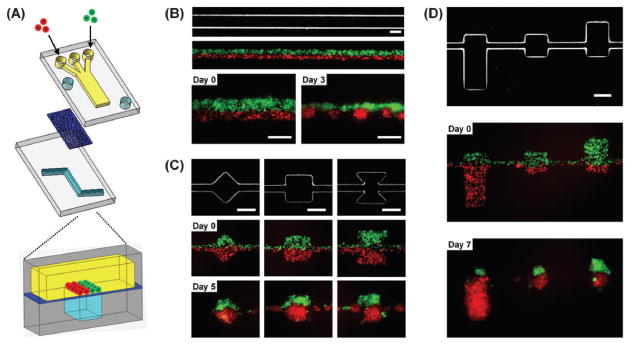
(a) Schematic illustration of the microfluidic device. Two PDMS channel layers are separated by a semi-porous polycarbonate membrane which is rendered resistant to cell adhesion. The top channel is a straight channel (2 mm in width) with a dead-end. The bottom channel consists of a straight channel with or without chambers. Cells are introduced into the top channel using multiple laminar flows. (b–d) Micrographs of bottom layer geometry and actual cellular patterning. (b) Cellular patterning on a single straight bottom channel (200 μm in width). Two kinds of cells, MDA-MB-231 cells (green) and COS7 cells (red), are juxtaposed in the top layer as fluid focuses them together into one channel in the bottom layer. Each type of cell self-aggregates to form multiple spheroids. (c, d) Cellular patterning on the bottom channel with distinct geometric features to control either the shape (c) or size (d) of individual spheroids. MDA-MB-231 cells were stably transfected with EGFP and COS7 cells were labeled with CellTracker red. Scale bars: 200 μm.
Cells were introduced into the top channel using gravity-driven flow while closing an inlet of the bottom layer. Different types of cell suspensions (typically, 105 cells mL−1) were poured into each inlet of the top channel simultaneously using a multi-pipette while keeping the outlet at a lower height (ca. 10 cm). The top channel defines the relative position of each cell type by laminar flow streams while the bottom channel dictates the final pattern cells will take. After the bottom channel region was covered with cells, the flow was stopped and the cell suspension in the inlets was replaced with culture medium. The cells were cultured under static conditions with daily medium exchange through the bottom channel layer.
Evaluation of mES cell differentiation
mES cell spheroids were imaged by fluorescence microscopy after 7 days in culture. Image analysis was carried out using MetaMorph software (Universal Imaging) to evaluate relative EGFP intensity of mES cell spheroids. 20 spheroids in 5 devices were used to analyze EGFP expression. The data were analyzed by T-test at a 99.9% confidence level.
Results and discussion
Formation of Janus spheroids
We previously reported a microfluidic system in which cells form spheroids of uniform size due to the physical confinement of microchannel walls.35,36 Although this approach was useful in obtaining uniformly sized spheroids, the confinement by the microchannels did not allow for cell growth and control of initial cell positioning to observe co-culture formation dynamics. Also, when co-culture spheroids were formed, the different cell types mixed together randomly because there was only one inlet for introduction of cells.36 Here we present an approach that patterns spheroids of multiple cell types with defined shape and position while facilitating spheroid growth.
Cells are patterned by flow that hydrodynamically focuses them on geometric features in the bottom layer. The device consists of two PDMS layers of microchannels separated by a semi-porous membrane (Fig. 1a). The top layer has a large straight channel that has a dead-end to facilitate capture of cells and formation/growth of spheroids. The bottom layer has geometric features which dictate the pattern cells will take since flow only occurs through the membrane into those features. By combining laminar flows,37,38 different cell types can be seeded simultaneously in well defined spatial arrangements. Two types of cells are introduced into the left and right inlet of the top channel. Culture media is introduced into the middle inlet as a third stream to minimize mixing of cell types as they flow through the channel. Fig. 1b shows two kinds of cells, breast cancer cells (MDA-MB-231) transfected with EGFP and monkey kidney cells (COS7) labeled with CellTracker red, juxtaposed in the top channel as fluid focuses them together into one channel in the bottom layer. Since the membrane is treated with Pluronic to block cell adhesion, cells self-aggregate and form patterned spheroids in defined positions.
The formation of each spheroid can be spatially controlled by the geometry of the bottom channel. When cells are pattered as a confluent layer over a continuous straight bottom channel, the cells self-aggregate and break up into several spheroids as shown in Fig. 1b. When two types of cells are patterned over a bottom channel with distinct geometric features, the cells form individual Janus spheroids (Fig. 1c). Furthermore, the cellular ratio of a Janus spheroid can be controlled by the respective area of the geometric feature under each laminar flow stream (Fig. 1d).
Geometric control of multiple co-cultures
The size and shape of the cellular patterning can be controlled by altering the geometry of the channels in the bottom layer (Fig. 2a). Cells introduced into the top channel are guided into position and shape of the features in the bottom layer. Fig. 2b shows cells forming individual spheroids on distinct side chambers of the bottom channel and continuously growing in their defined locations for fourteen days. The long-term culture is enabled by the semi-porous membrane which allows culture media to exchange from the bottom channel with minimal perturbation of the spheroids positioning. The ability of co-culture spheroids to conform to more complex patterns both initially mixed and patterned is shown in Fig. 2c and d, respectively. In addition, co-culture spheroids of multiple cell types can be achieved by adding additional laminar streams. Fig. 3a demonstrates the simultaneous patterning of five distinct cell groups by using a five inlet main-channel. The ability to control the positioning of different cell types can be seen in Fig. 3b where only one of the red groups of cells was patterned over the “head” region of the “human-shaped” bottom channel.
Fig. 2. Arbitrary geometry control of cellular patterning.
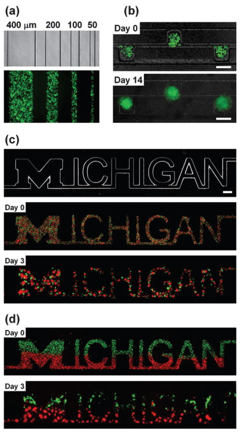
(a) An optical image of the bottom channels and a fluorescent image of cells patterned on the bottom channels. (b) Time-lapse images of cells patterned in a device. The bottom channel consists of side-chambers (200 × 200 μm) and a microchannel (50 μm in width) and the top channel is a straight channel (500 μm in width). (c, d) Time-lapse images of patterned cells; mixed co-culture (c) or joint co-culture (d) of MDA-MB-231 cells (green) and COS7 cells (red). The bottom channel is “Michigan” shape (mainly 200 μm in width) (top image in (c)) and the top channel is a straight channel (2 mm in width). Cells self-aggregated and formed spheroids while maintaining the shape of the letters. Scale bars: 200 μm (b) and 500 μm (c, d).
Fig. 3. Patterning co-culture of multiple cell types.
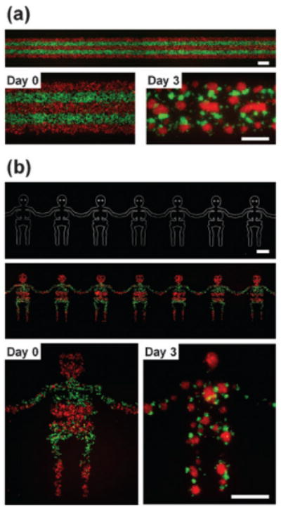
(a) Fluorescent images of cells patterned on a straight bottom channel (1 mm in width). The top channel consists of five inlet channels that converge into a main channel with a width of 1 mm. Two kinds of cells were patterned as five equal lines alternately and formed spheroids that contacted each other after 3 days in culture. (b) An optical image of the bottom channel and fluorescent images of patterned cells. Two kinds of cells were patterned as “human” shapes while keeping alternate five equal lines. Scale bars: 500 μm.
Formation dynamics of heterogeneous spheroids
The effect that spatial patterning has on co-culture spheroid formation was determined by comparing cell arrangement dynamics with the conventional initially mixed co-cultures (Fig. 4). Breast cancer cells (MDA-MB-231) were co-cultured with either human umbilical vein endothelial cells (HUVECs), monkey kidney cells (COS7), or hepatocarcinoma cells (HepG2). HUVECs uniformly dispersed inside the MDA-MB-231 spheroids for both initially mixed and pattered co-culture conditions (Fig. 4b and f), similar to previous reports.39 COS7 cells and MDA-MB-231 cells were not miscible; both types of cells self-aggregated in two distinct groups of spheroids either in an alternating fashion for the mixed condition (Fig. 4c) or side-by-side for the patterned condition (Fig. 4g). Interestingly however, HepG2 cells tended to be located on the outer surface of the spheroids in mixed co-culture (Fig. 4d), whereas they formed separate spheroids when patterned side-by-side to MDA-MB-231 cells (Fig. 4h). This result suggests that the final organization of co-culture spheroids can also depend on initial cellular positioning in addition to intrinsic cell characteristics such as cellular surface tension17 and adhesion proteins.14
Fig. 4.
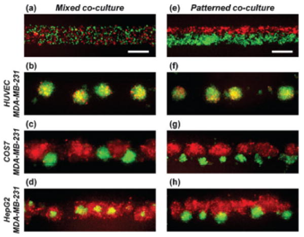
Formation of heterogeneous co-culture spheroids. Fluorescent images of mixed co-culture (a–d) and patterned co-culture (e–h) of two kinds of cells after 7 days in culture. MDA-MB-231 cells were co-cultured with either HUVECs (b, f), COS7 cells (c, g), or HepG2 cells (d, h). MDA-MB-231 cells were stably transfected with EGFP and all the other cells were labeled with CellTracker red. The bottom channel is a straight channel with a width of 200 μm. Scale bars: 200 μm.
Evaluation of mES cell differentiation in 3D co-culture
We applied this patterning method to evaluate ES cell differentiation. mES cells stably transfected with OCT4-EGFP and HepG2 cells labeled with CellTracker red were co-cultured as above, either initially mixed or patterned. As in the case of our results with breast cancer cells, HepG2 cells tended to be found on the outside of the spheroids when initially mixed, in both non-adherent dishes and the microchannel (Fig. 5a and b). For patterned co-culture, the HepG2 cells still tended to progressively surround the mES cells but Janus spheroids could still be maintained at about 10% yield (typically 5 spheroids in each device) after 7 days in culture. It can be seen that HepG2 cells inhibited proliferation and induced a loss in EGFP expression (indicative of OCT4 expression) in neighboring mES cells. An intensity line scan for EGFP expression is shown for both mixed (Fig. 5e) and patterned (Fig. 5f) co-cultures after 7 days in culture. The graphs show that mixed co-cultures resulted in a uniformly lower EGFP-expression as compared to the asymmetric expression levels in the patterned co-cultures (Fig. 5g and h). Downregulation of the OCT4 promoter and lower EGFP expression indicates a decrease in the pluripotency of cells. The relative EGFP intensity of mES cells without any cell contact in the patterned spheroids is significantly higher than other regions, suggesting that cell–cell contact and cytokines produced by the mES cells themselves maintain pluripotency after 7 days in culture. This regional downregulation observed in Janus spheroids suggests the possibility that spatial differentiation of 3D constructs can be controlled by intercellular positioning.
Fig. 5.
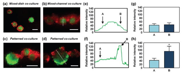
Evaluation of mES cell differentiation using Janus spheroids. (a–d) Fluorescent images of mixed co-culture (a, b) and patterned co-culture (c, d) of mES cells and HepG2 cells. mES cells were stably transfected with OCT4-EGFP and HepG2 cells were labeled with CellTracker red. (a, b) mES cells and HepG2 cells were mixed and then cultured in a non-adherent dish for 3 days (a) or in a microfluidic device for 7 days (b). HepG2 cells tended to be located on the outside of the spheroids. (c, d) mES cells and HepG2 cells were patterned juxtaposed and cultured for 7 days. The bottom channel is a straight channel with a width of 200 μm. (e) and (f) are relative EGFP intensity profiles of the white dotted line shown in (b) and (d), respectively. (g, h) Relative EGFP intensity of mES cells at points A and B shown in (e) and (f), respectively (average of 20 spheroids). Scale bars: 200 μm. *p < 0.001.
Conclusion
We present a microfluidic method to form 3D co-culture spheroids of various geometries and compositions. This patterning method is one of few to spatially arrange multi-cell type 3D constructs; and it is the only method currently that also allows observation of spheroid formation in a single step. By simply changing the geometric pattern of the channel features, spatially-arbitrary cellular constructs can be formed to investigate the effect shape has on tissues formation. The compartmentalization of the spheroids from the media exchanging channel enables convenient and rapid exchange of nutrients and/or morphogens facilitating more complex dynamics to be observed both in real-time and long term experiments. In addition, the capability to form many spheroids in parallel allows studies to be performed in high-throughput. We demonstrate that this patterning method can be used to maintain cells in pre-determined arrangements that otherwise would be impossible due to their intrinsic cellular interaction dynamics, such as the formation of segregated “Janus” spheroids. Janus spheroids of HepG2 cells and mES cells can be formed by this patterning method, resulting in the regional differentiation of the mES cells. This demonstrates that cellular differentiation can be controlled by cell–cell positioning. This cellular patterning method opens new possibilities for understanding and manipulating interactions between different cell types in 3D.
Acknowledgments
We thank the NIH for support (HL-084370, P50CA093990, R01CA136553, 1R01CA136829, GM-06695, and NS-048187).
References
- 1.Abbott A. Nature. 2003;424:870–872. doi: 10.1038/424870a. [DOI] [PubMed] [Google Scholar]
- 2.Yamada KM, Cukierman E. Cell. 2007;130:601–610. doi: 10.1016/j.cell.2007.08.006. [DOI] [PubMed] [Google Scholar]
- 3.Griffith LG, Swartz MA. Nat Rev Mol Cell Biol. 2006;7:211–224. doi: 10.1038/nrm1858. [DOI] [PubMed] [Google Scholar]
- 4.Bissell MJ, LaBarge MA. Cancer Cell. 2005;7:17–23. doi: 10.1016/j.ccr.2004.12.013. [DOI] [PMC free article] [PubMed] [Google Scholar]
- 5.Matsuda N, Shimizu T, Yamato M, Okano T. Adv Mater. 2007;19:3089–3099. [Google Scholar]
- 6.Mueller-Klieser W. Am J Physiol Cell Physiol. 1997;273:C1109–C1123. doi: 10.1152/ajpcell.1997.273.4.C1109. [DOI] [PubMed] [Google Scholar]
- 7.Friedrich J, Ebner R, Kunz-Schughart LA. Int J Radiat Biol. 2007;83:849–871. doi: 10.1080/09553000701727531. [DOI] [PubMed] [Google Scholar]
- 8.Lin RZ, Chang HY. Biotechnol J. 2008;3:1172–1184. doi: 10.1002/biot.200700228. [DOI] [PubMed] [Google Scholar]
- 9.Townes PL, Holtfreter J. J Exp Zool. 1955;128:53–120. [Google Scholar]
- 10.Steinberg MS. Science. 1963;141:401–408. doi: 10.1126/science.141.3579.401. [DOI] [PubMed] [Google Scholar]
- 11.Sutherland RM. Science. 1988;240:177–184. doi: 10.1126/science.2451290. [DOI] [PubMed] [Google Scholar]
- 12.Armstrong PB. Crit Rev Biochem Mol Biol. 1989;24:119–149. doi: 10.3109/10409238909086396. [DOI] [PubMed] [Google Scholar]
- 13.Steinberg MS, Takeichi M. Proc Natl Acad Sci U S A. 1994;91:206–209. doi: 10.1073/pnas.91.1.206. [DOI] [PMC free article] [PubMed] [Google Scholar]
- 14.Foty RA, Steinberg MS. Dev Biol. 2005;278:255–263. doi: 10.1016/j.ydbio.2004.11.012. [DOI] [PubMed] [Google Scholar]
- 15.Wartenberg M, Donmez F, Ling FC, Acker H, Hescheler J, Sauer H. FASEB J. 2001;15:995–1005. doi: 10.1096/fj.00-0350com. [DOI] [PubMed] [Google Scholar]
- 16.Kelm JM, Sanchez-Bustamante CD, Ehler E, Hoerstrup SP, Djonov V, Ittner L, Fussenegger M. J Biotechnol. 2005;118:213–219. doi: 10.1016/j.jbiotec.2005.03.016. [DOI] [PubMed] [Google Scholar]
- 17.Krieg M, Arboleda-Estudillo Y, Puech PH, Kafer J, Graner F, Muller DJ, Heisenberg CP. Nat Cell Biol. 2008;10:429–436. doi: 10.1038/ncb1705. [DOI] [PubMed] [Google Scholar]
- 18.Albrecht DR, Underhill GH, Wassermann TB, Sah RL, Bhatia SN. Nat Methods. 2006;3:369–375. doi: 10.1038/nmeth873. [DOI] [PubMed] [Google Scholar]
- 19.Du Y, Lo E, Ali S, Khademhosseini A. Proc Natl Acad Sci U S A. 2008;105:9522–9527. doi: 10.1073/pnas.0801866105. [DOI] [PMC free article] [PubMed] [Google Scholar]
- 20.Gartner ZJ, Bertozzi CR. Proc Natl Acad Sci U S A. 2009;106:4606–4610. doi: 10.1073/pnas.0900717106. [DOI] [PMC free article] [PubMed] [Google Scholar]
- 21.Liu WF, Chen CS. Adv Drug Delivery Rev. 2007;59:1319–1328. doi: 10.1016/j.addr.2007.08.011. [DOI] [PMC free article] [PubMed] [Google Scholar]
- 22.Douglas ES, Chandra RA, Bertozzi CR, Mathies RA, Francis MB. Lab Chip. 2007;7:1442–1448. doi: 10.1039/b708666k. [DOI] [PubMed] [Google Scholar]
- 23.Lee JY, Shah SS, Yan J, Howland MC, Parikh AN, Pan T, Revzin A. Langmuir. 2009;25:3880–3886. doi: 10.1021/la803635r. [DOI] [PMC free article] [PubMed] [Google Scholar]
- 24.Mironov V, Visconti RP, Kasyanov V, Forgacs G, Drake CJ, Markwald RR. Biomaterials. 2009;30:2164–2174. doi: 10.1016/j.biomaterials.2008.12.084. [DOI] [PMC free article] [PubMed] [Google Scholar]
- 25.Torisawa Y, Takagi A, Nashimoto Y, Yasukawa T, Shiku H, Matsue T. Biomaterials. 2007;28:559–566. doi: 10.1016/j.biomaterials.2006.08.054. [DOI] [PubMed] [Google Scholar]
- 26.Wu LY, Carlo DD, Lee LP. Biomed Microdevices. 2008;10:197–202. doi: 10.1007/s10544-007-9125-8. [DOI] [PubMed] [Google Scholar]
- 27.Toh YC, Lim TC, Tai D, Xiao G, van Noort D, Yu H. Lab Chip. 2009;9:2026–2035. doi: 10.1039/b900912d. [DOI] [PubMed] [Google Scholar]
- 28.Slack JMW. Nat Rev Genet. 2002;3:889–895. doi: 10.1038/nrg933. [DOI] [PubMed] [Google Scholar]
- 29.Heisenberg CP, Solnica-Krezel L. Curr Opin Genet Dev. 2008;18:311–316. doi: 10.1016/j.gde.2008.07.011. [DOI] [PMC free article] [PubMed] [Google Scholar]
- 30.Nelson CM, VanDuijn MM, Inman JL, Fletcher DA, Bissell MJ. Science. 2006;314:298–300. doi: 10.1126/science.1131000. [DOI] [PMC free article] [PubMed] [Google Scholar]
- 31.Keller R, Shook D, Skoglund P. Phys Biol. 2008;5:15007. doi: 10.1088/1478-3975/5/1/015007. [DOI] [PubMed] [Google Scholar]
- 32.Ninomiya H, Winklbauer R. Nat Cell Biol. 2008;10:61–69. doi: 10.1038/ncb1669. [DOI] [PubMed] [Google Scholar]
- 33.Ruiz SA, Chen CS. Stem Cells. 2008;26:2921–2927. doi: 10.1634/stemcells.2008-0432. [DOI] [PMC free article] [PubMed] [Google Scholar]
- 34.Luker KE, Gupta M, Luker GD. BioTechniques. 2009;47:625–632. doi: 10.2144/000113126. [DOI] [PMC free article] [PubMed] [Google Scholar]
- 35.Torisawa Y, Chueh B, Huh D, Ramamurthy P, Roth TM, Barald KF, Takayama S. Lab Chip. 2007;7:770–776. doi: 10.1039/b618439a. [DOI] [PubMed] [Google Scholar]
- 36.Hsiao AY, Torisawa Y, Tung YC, Sud S, Taichman RS, Pienta KJ, Takayama S. Biomaterials. 2009;30:3020–3027. doi: 10.1016/j.biomaterials.2009.02.047. [DOI] [PMC free article] [PubMed] [Google Scholar]
- 37.Takayama S, McDonald JC, Ostuni E, Liang MN, Kenis PJA, Ismagilov RF, Whitesides GM. Proc Natl Acad Sci U S A. 1999;96:5545–5548. doi: 10.1073/pnas.96.10.5545. [DOI] [PMC free article] [PubMed] [Google Scholar]
- 38.Wong AP, Perez-Castillejos R, Love JC, Whitesides GM. Biomaterials. 2008;29:1853–1861. doi: 10.1016/j.biomaterials.2007.12.044. [DOI] [PMC free article] [PubMed] [Google Scholar]
- 39.Timmins NE, Dietmair S, Nielsen LK. Angiogenesis. 2004;7:97–103. doi: 10.1007/s10456-004-8911-7. [DOI] [PubMed] [Google Scholar]


