Abstract
Robotic assistance enhances conventional endoscopy; yet, limitations have hindered its mainstream adoption for cardiac surgery. HeartLander is a miniature mobile robot that addresses several of these limitations by providing precise and stable access over the surface of the beating heart in a less-invasive manner. The robot adheres to the heart and navigates to any desired target in a semiautonomous fashion. The initial therapies considered for HeartLander generally require precise navigation to multiple surface targets for treatment. To balance speed and precision, we decompose any general target acquisition into navigation to the target region followed by fine positioning to each target. In closed-chest, beating-heart animal studies, we demonstrated navigation to targets located around the circumference of the heart, as well as acquisition of target patterns on the anterior and posterior surfaces with an average error of 1.7 mm. The average drift encountered during station-keeping was 0.7 mm. These preclinical results demonstrate the feasibility of precise semiautonomous delivery of therapy to the surface of the beating heart using HeartLander.
Index Terms: Beating-heart surgery, medical robotics, minimally invasive surgery, mobile robot motion planning
I. Introduction
A. Robotic Minimally Invasive Surgery
Minimally invasive thoracoscopic surgery avoids the trauma associated with cutting the sternum and expanding the ribcage by inserting rigid tools through a set of incisions made between the ribs. This technique can be augmented with teleoperated instrumentation, through which the motions of the surgeon's hands are mimicked by a set of robotically actuated tools that are located inside the patient [1], [2]. Although these robotic systems improve upon conventional thoracoscopy by increasing dexterity, restoring hand–eye coordination, and reducing fatigue, they have stability and access limitations when used in beating-heart surgery.
Surgery on the beating heart is a major objective in the field because cardiopulmonary bypass, which allows the heart to be stopped, can lead to serious complications [3], [4]. Local mechanical immobilization of the epicardium—the outer surface of the heart—is the clinical approach generally followed today for beating-heart surgery. Although endoscopic mechanical stabilizers can be used to immobilize a small region of the epicardial surface, they add clutter to an already confined workspace and can adversely affect the electrophysiological and mechanical performance of the heart [5]–[7]. These devices also exhibit 1.5–2.4 mm of residual motion within the field of stabilization [8], [9]. Although there is research into active mechanical stabilizers to reduce this motion, endoscopic stabilization in 3-D has yet to be demonstrated [10]. It has been suggested that the failure to adequately address the issue of organ motion compensation has contributed to the lack of wider acceptance of robotics in beating-heart surgery [8], [11].
As an alternative, several researchers in robot-assisted coronary artery bypass grafting surgery are investigating active compensation of heartbeat motion by tracking the epicardium and moving the tool tips accordingly [12]–[15], yet this research problem is unresolved. In addition to the challenges of modeling or tracking the heart surface, active compensation requires considerable cost for high-bandwidth actuation to manipulate in at least 3 degrees of freedom (DOFs) over a relatively large workspace [12].
Access limitations are also present in robotic thoracoscopy. The intercostal approach requires differential ventilation and deflation of the left lung to access the heart, which necessitates general anesthesia and adds to the overall morbidity of the procedure. Significant changes in the location of the operative site during the procedure may also require additional incisions and reinsertion of the endoscopic tools. Meanwhile, distal regions of the heart, such as the posterior left ventricle, remain difficult to reach using an intercostal approach. All of these limitations result from the fact that teleoperated robots are an extension of the same endoscopic concept that has existed for over 100 years [16], which is not particularly well-suited for operation on the beating heart.
B. HeartLander Concept
To address the problems that may hinder the adoption of thoracoscopic robots for cardiac surgery, namely physiological motion and access limitations, we have developed HeartLander—a miniature mobile robot to provide precise and stable access to the epicardial surface of the beating heart (see Fig. 1). The robot adheres to the epicardium using vacuum pressure, which has been demonstrated to be safe in the case of mechanical cardiac stabilizers [17], [18]. By attaching directly to the epicardium, the robot is located in the moving reference frame of the beating heart, thus passively compensating for both heartbeat and respiratory motion. The robot is equipped with actuators and a tracking sensor for semiautonomous navigation to specified targets. Locomotion enables HeartLander to reach areas of the epicardium that are difficult to access using intercostal thoracoscopy and to radically change operative fields from a single incision [19].
Fig. 1.
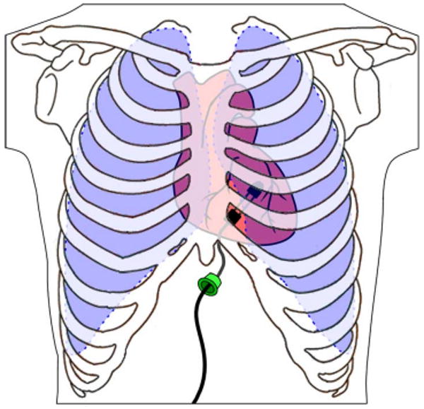
HeartLander concept (the ribs and lungs are shown transparent, while the skin and pericardium are not shown). The robot is inserted through an incision below the sternum, adheres to the heart surface using suction, and provides semiautonomous access to any specified target on the heart surface.
The locomotive capabilities of HeartLander also allow the insertion site of the robot to be independent of the operative site for the procedure to be carried out. Accordingly, HeartLander is deployed through a percutaneous incision below the xiphoid process of the sternum. Unlike an intercostal approach, this subxiphoid approach provides access to the heart without breaching the space occupied by the lungs (see Fig. 1), thus obviating differential ventilation and lung deflation [20], [21]. Therefore, the insertion of HeartLander does not require general anesthesia and, in principle, could be performed on an outpatient basis.
Like an endoscope, HeartLander has a working channel through which flexible therapeutic devices can be applied to the heart. It has successfully deployed several therapeutic devices to beating porcine (pig) hearts, including injection needles, pacing leads, and ablation catheters [22], [23].
C. Prior Work in Medical Mobile Robotics
The majority of research into mobile robotics for medical application has focused on traversing the large intestine using inchworm-like robots [24]–[26]. Although HeartLander has a mechanical design similar to these robots, it must additionally compensate for organ motion and operate in an extremely confined space. As the heart is not a luminal organ, like the large intestine, HeartLander must also employ robotic navigation techniques to reach target locations on the epicardium.
Another application within the digestive system is the diagnostic exploration of the small intestine with miniature passive pill cameras that are propelled by natural peristalsis [27], [28]. Although there is active research into using onboard radio-frequency coils and battery-powered legs to control the descent of these devices, they currently exist only as passive diagnostic tools [29], [30]. The ability of HeartLander to navigate over the surface of the heart allows it to accurately position tools for therapy, as demonstrated in previous work [22], [23].
Researchers have also developed a wheeled mobile robot to travel over the abdominal organs [31]. This robot travels over relatively stationary organs for diagnostic purposes and enjoys plentiful overhead space within the insufflated abdomen.
Within the field of electrophysiology, there are commercially available systems that provide active guidance of catheters through the inside of the heart using magnetism [32] and robotics [33]. These devices operate within the stationary reference frame of the operating table and, therefore, can experience difficulties in positioning stability and precision due to organ motion.
HeartLander is the only organ-mounted mobile robot known to the authors whose purpose is to compensate for organ motion, improve access, and enhance positioning accuracy using autonomous features. In Section II, we describe the intrapericardial space in which HeartLander operates and the experimental goals to demonstrate autonomous navigation and positioning within this environment. The designs of the robotic system and control system to accomplish these goals are then described in Sections III and IV, respectively. Section V defines the experimental protocol and evaluation criteria that were used to test the HeartLander system. In Section VI, we present the navigation, positioning, and adherence stability results from a series of animal studies using a beating porcine model with the chest closed and pericardium intact. A portion of the positioning data was reported in [34].
II. Problem Definition
The goal of this paper is to demonstrate that the design of the HeartLander robotic system has resulted in a vehicle that can provide minimally invasive access to the epicardium in a precise and stable manner that will accommodate the administration of a variety of intrapericardial therapies.
A. Intrapericardial Environment
HeartLander must operate within an environment that presents severe mechanical constraints from the surrounding anatomy and disturbance due to vigorous physiological motion. There is no free space around the heart in situ because it is surrounded by other organs. The heart is enclosed within a two-layered sac called the pericardium. The fibrous outer layer of the pericardium restrains the heart, while the serous inner layer reflects back over the outside of the heart to form the intrapericardial space (see Fig. 2). This space is naturally filled with only a thin film of fluid and has a height of less than 1 mm in situ [35]. Accordingly, HeartLander must create its own clearance space by distending the pericardium.
Fig. 2.
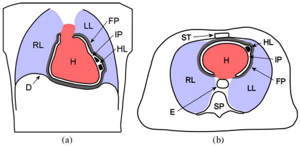
HeartLander (HL) in the intrapericardial space (IP) in (a) coronal view and (b) axial view. The surrounding organs include the heart (H), right lung (RL), left lung (LL), diaphragm (D), fibrous pericardium (FP), sternum (ST), spinal column (SP), and esophagus (E). The sizes of the intrapericardial space and fibrous pericardium have been exaggerated for clarity. The robot tether is not shown.
Points on the epicardial surface of the heart undergo large displacements at high speeds during natural beating. Shechter et al. measured the maximum 3-D resultant displacement of epicardial points to be 23 mm, with a maximum velocity of 131 mm/s [36]. HeartLander must generate sufficient epicardial traction to resist the shearing forces caused by these displacements and high velocities between the epicardium and the pericardium.
The intrapericardial therapies that are envisioned for HeartLander are the injection of regenerative materials for heart failure [37], lead placement for resynchronization [38], and epicardial ablation for arrhythmia [39]. These therapies share three main characteristics: They can be completed from within the intrapericardial space, they require flexible 1-DOF tools, and they comprise multiple treatments made at precise locations on the epicardium. In previous work, we have demonstrated the feasibility of administering single or limited applications of each of these therapies from HeartLander [22], [23].
B. Experimental Goals
The goal of the experimental testing is to demonstrate the requisite technical capabilities for HeartLander to serve as a semiautonomous delivery vehicle for the aforementioned intrapericardial therapies. Accordingly, HeartLander must demonstrate the ability to deliver an end-effector to a series of target locations on the beating heart in a precise and stable manner with the chest closed and pericardium intact. The acquisition of a target pattern with arbitrary size, shape, and location can be decomposed into two tasks: navigation to the general target region, followed by fine positioning to each of the local targets within the region. In this manner, HeartLander acts as a mobile robot during the navigation task and as a manipulator during the positioning task. This decomposition allows the control-system design to meet the different requirements for each of the navigation and fine-positioning tasks, which will then be evaluated separately during testing on closed-chest porcine models with intact pericardia.
The specific goal of the navigation testing is to demonstrate semiautonomous navigation from the apex of the heart to regions that span the circumference of the ventricles of the beating heart, which is shown schematically in Fig. 3(a) and (b). This task will demonstrate the ability of HeartLander to reach any location on the ventricles in a controlled manner for treatment. The semiautonomous control architecture will allow the surgeon to specify his or her navigation goal and intent to proceed while leaving the lower level details to the robot. Controlled robotic navigation will allow HeartLander to avoid sensitive regions of the heart and generate diagnostic mappings when equipped with appropriate sensors. The apex is selected as the origin for all navigation paths because it is the anatomical location of the robot insertion beneath the pericardium. The ventricles are chosen as the termination points for the navigation trials because they are the most clinically relevant regions for our intrapericardial therapies. After the robot has successfully acquired the specified navigation target, the control system must notify the surgeon and switch to fine-positioning mode to begin the second component of the general acquisition decomposition.
Fig. 3.
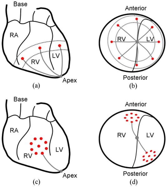
(a) Anterior view and (b) apex view of the navigation task. The targets are shown by the dark circles and the paths by the gray lines. The circumference of the ventricles is the region between the broken lines. (c) Anterior view of the positioning task. (d) Apex view of the positioning task.
The goal for the fine-positioning evaluation is to acquire all targets located within a predefined local pattern on a single ventricle of the beating heart in a semiautonomous manner. Fig. 3(c) and (d) shows two such patterns, which are located on the anterior and posterior surfaces of the heart. This will demonstrate the ability of HeartLander to provide precise local positioning for multiple epicardial treatments that compose a therapy. In clinical practice, this positioning task will directly follow navigation to the general target region, i.e., acquisition of the navigation target. Specifically, we selected a test pattern comprising multiple targets located around the circumference of a circle, with one additional target in the center of the circle, which is illustrated in Fig. 3(c) and (d). This pattern has sufficient size and complexity to simulate our intrapericardial therapies, e.g., the injection of regenerative materials into a myocardial infarct or the creation of an ablation lesion. It is important that the test pattern does not span the boundary groove between the ventricles, as this has been found empirically to lead to increased positioning error. We do not constrain the orientation of the robot at the targets because our therapeutic applications specify only the locations for the treatments. To demonstrate sufficient accuracy, our goal is to acquire the positioning targets for HeartLander within 2 mm on the closed-chest beating porcine heart. This requirement is consistent with the highest level of accuracy reported using a commercially available robotic system for catheter positioning within the heart [33].
For both the navigation and fine-positioning components of target acquisition, HeartLander must provide a stable platform relative to the heart surface in order to operate safely on the unconstrained epicardium. Our goal for stability is to maintain the maximum resultant drift of the robot below 1.5 mm for a period of 30 s while gripping the epicardium. This requirement is consistent with the stability maintained by commercially available mechanical stabilizers, which exhibit a residual motion of 1.5–2.4 mm [11], [12]. The duration of the stability period was estimated from the maximum length of time that would be required for a single treatment application for our envisioned intrapericardial therapies.
III. Robot Design
The clinical therapies envisioned for HeartLander require the robot to provide navigation, fine positioning, and stability within the intrapericardial environment. The design criteria that enable these capabilities are miniature size, robust mechanical structure, high actuation forces, high traction forces, and navigation and positioning functionality. To meet these criteria, the HeartLander design is a tethered mobile robot that uses vacuum pressure to maintain prehension of the epicardium and drive wires for actuation. With one section fixed to the epicardium, the robot is also able to act effectively as a manipulator. This design addresses the difficulties of introducing and accurately positioning an end-effector within the constrained and turbulent intrapericardial environment.
A. Tethered Design
The HeartLander system consists of a miniature crawling robot that is connected to a suite of offboard support instrumentation through a flexible tether. This design allows the therapeutic portion of the robot (i.e., the crawler) to be small, robust, lightweight, and potentially disposable. Fig. 4 shows a diagram and photograph of the entire HeartLander system. Because the intrapericardial space has less than 1 mm of clearance, HeartLander must expand the pericardium to create its own clearance (see Fig. 2). Accordingly, the size of the robot must be made sufficiently small such that the pericardium and surrounding organs do not impede the motion of the robot. By offloading the functional components of the robot—i.e., the motors, vacuum pump, and valves—the tethered crawling portion can be made sufficiently small for this purpose. The tethered design also allows the crawler to be mechanically simple and robust, which is critical for reliable operation in the constrained and volatile intrapericardial environment. From a safety standpoint, the tether allows the crawler to be electrically passive, which is critical considering the electrical sensitivity of the epicardium. Additionally, the tether can be used to manually remove the crawler in the event of a malfunction.
Fig. 4.
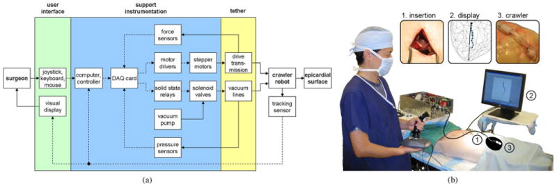
(a) Schematic diagram of the HeartLander system, which comprises the user interface, the support instrumentation, and the tethered crawling robot. Mechanical flow is indicated by solid lines, while data flow is shown by broken lines. (b) Operating room during in vivo animal testing, showing the surgeon interacting with the HeartLander system. The approximate heart shape and robot location inside the body have been illustrated for clarity. Insets show larger views of 1) the subxiphoid insertion, 2) the graphical display, and 3) the crawling robot.
The maneuverability of the crawling robot is not significantly hindered by the tether because the intrapericardial space is a single continuous volume. This means that the epicardium of each of the four chambers of the heart can be reached from the apex by a relatively straight trajectory [see Fig. 3(a) and (b)]. Accordingly, tight turning maneuvers that would be difficult to execute with a tether are not necessary. Additionally, the maximum required length of travel for the robot is limited by the distance from the robot insertion location to the base of the heart, which is approximately 120 mm in humans [40]. In our present design, the tether is 650 mm in length.
B. Crawling Robot
The crawling portion of the robot that enters the intrapericardial space consists of two tandem bodies that independently adhere to epicardium (see Fig. 5). Each body is 5.5 mm × 8 mm × 8 mm (H × W × L) and weighs 0.3 g. The distance between the front and rear bodies is controlled by a pair of nitinol drive wires (0.3 mm diameter) that run longitudinally through the tether, thereby connecting the front body and the two offboard stepper motors (size M23, U.S. Digital Corporation). The use of stepper motors allows for simple position control of the drive wires. Low-friction plastic sheaths (0.38 mm ID; 0.69 mm OD), which are attached to the rear body, encapsulate the drive wires as they pass through the tether and transmit the wire forces to the rear body.
Fig. 5.
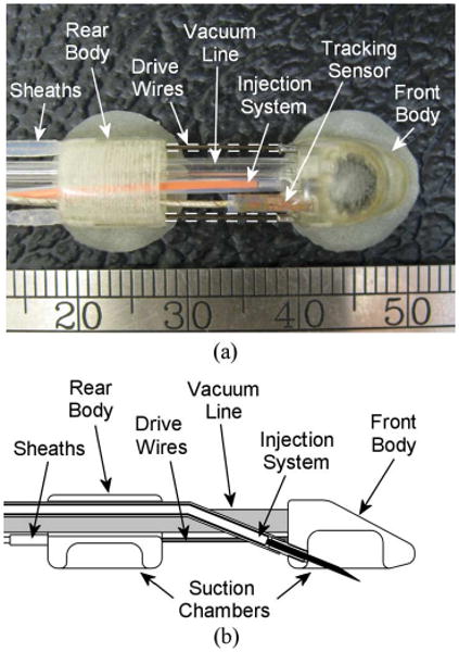
(a) Top view of the HeartLander crawling robot. (b) Crawling robot with a midline cutaway to show structure.
The two DOFs provided by the pair of drive wires allow the angle and distance between the bodies to be varied by changing the lengths of the wires exposed between the bodies. This type of robot, which bends continuously along its length through elastic deformation rather than at discrete joints, is known as a continuum robot. The drive wire configuration exhibits high bending compliance in the direction normal to the transverse plane of the robot, which permits the pericardium to naturally force the robot into contact with the heart surface. Accordingly, navigation on the heart surface reduces to a 2-D problem, where the two DOFs provided by the drive wires are sufficient to span the epicardium. This continuum robot design facilitates a simple and small form factor for the crawler that passively conforms to the rapidly varying curvature of the heart with no need for a complicated force-feedback system [41]. When the bodies are brought close together, the wire compliance diminishes, thus providing a more stable connection between the bodies. The nitinol drive wires are used solely for their superelasticity and are not actuated using thermal variation. This elasticity is sufficiently high such that wire buckling would not result in damage to the robot or the surrounding intrapericardial structures.
Each body contains an independent suction gripper into which epicardial tissue is drawn to generate traction on the heart during locomotion and treatment. The chamber of each suction gripper is 6 mm in diameter and 3.5 mm deep (see Fig. 5). The open cylindrical suction chamber shape was chosen over other forms that included multiple chambers and protrusions, because it demonstrated the highest epicardial traction of 4.0 N [42]. Vacuum pressure is supplied to the grippers from an offboard pump through vacuum lines in the tether. The pressure of each gripper is controlled by a solenoid valve located in the offboard instrumentation. When activated for traction, the vacuum pressure is maintained between 400 and 600 mmHg. This pressure range is the same as that used in mechanical cardiac stabilizers and does not permanently damage the epicardium [17], [18]. The suction grippers on HeartLander should cause even less epicardial damage than mechanical stabilizers because they are applied for a far shorter duration and move passively with the epicardium instead of constraining it. Thin latex strips surround the periphery of each suction gripper, thereby helping to create a vacuum seal with the epicardium.
C. Remote Injection System
A remote injection system to perform myocardial injections from the intrapericardial space has been developed to fit within the working channel of the HeartLander crawler. When the crawler is in motion, the 27-gauge needle is safely housed inside the working channel of the front body. When the crawler front body reaches the desired target location, the needle is extended into the tissue that has been drawn into the active front-body suction gripper [see Fig. 5(b)]. The proximal end of the needle injection system is connected to a syringe. The depth of the needle penetration into the tissue is set by an adjustable mechanical constraint within the range of 1–5 mm.
IV. Control System Design
The acquisition of any general target pattern can be decomposed into two distinct tasks: navigating from the initial location to the general target pattern vicinity and then performing a series of fine-positioning motions to each of the individual target points. By separating an acquisition into these two tasks, the control system is able to reduce the total acquisition time by altering the balance between speed and accuracy, as warranted by the tasks. A block diagram of the control system can be seen in Fig. 6(a). During the navigation task, the control system generates a path to the target vicinity and then uses the data from a tracking sensor onboard the robot to follow the path in a semiautonomous fashion. After reaching the general target vicinity, the navigation task is complete. The control system subsequently acquires each target in the pattern through a series of fine-positioning motions of the front body with the rear body fixed to the epicardium. In this manner, any number of targets at arbitrary locations on the epicardial surface can be acquired by the control system.
Fig. 6.
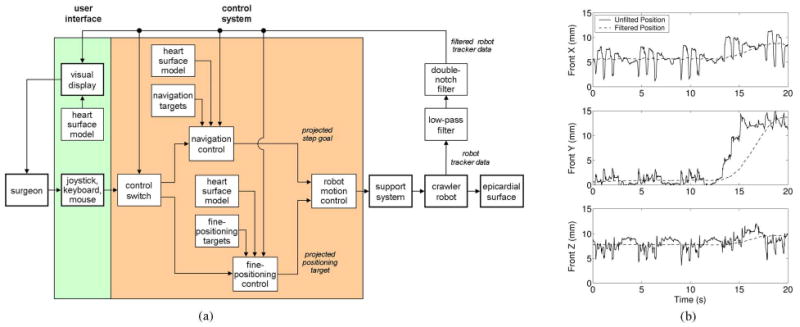
(a) Control architecture for the HeartLander system. (b) (Solid line) Raw and (broken line) filtered 3-D position data collected from the 6-DOF magnetic tracking sensor mounted on the crawling robot during locomotion on a beating porcine heart. The heartbeat and respiration motion are clear during the first 13 s of resting, at which time, locomotion begins.
A. Electromagnetic Tracking for Display and Localization
The graphic display and robot localization for control use the data from an electromagnetic tracking system (micro-BIRD, Ascension Technologies, Burlington, VT) [43]. The position and orientation of a miniature tracking sensor, which is located on the front body of the crawler (see Fig. 5), are measured in real time with respect to a magnetic transmitter attached to the operating table. This method of tracking does not require a line of sight between the sensor and the transmitter and is, thus, well suited for tracking tools located inside the body [see Fig. 6(b)]. The tracking system has a reported static translational and angular accuracy of 1.4 mm and 0.5°, respectively, within the transmitter workspace. The reported translational and angular resolution are 0.5 mm and 0.1°, respectively.
The graphic display generates a 2-D projection of the 3-D location of the robot on a geometric representation of the heart surface (see Fig. 7). The animal-specific heart-surface model for the display is generated immediately prior to each animal trial. The surgeon first traces the epicardial surface of the beating heart for approximately 3–5 min, with a probe carrying an electromagnetic tracking sensor, to generate a 3-D point cloud of the heart surface. Ellipses are fit to the subsets of points located within the adjacent coronal slices of the total point cloud, with a typical slice resolution of 1–2 mm. A 3-D convex hull is then fitted to the perimeter ellipses using the software package MATLAB (see [22] for additional details). This technique of generating the heart-surface model does not take into account the heartbeat or respiratory motion during the surface tracing. Accordingly, the point cloud and the corresponding surface model represent the average position of the heart over the physiological cycles. No anatomical landmarks are represented on the surface model.
Fig. 7.
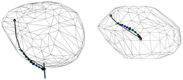
Screenshots from the graphic user interface during locomotion trial on the lateral wall of the left ventricle.
For both the navigation and fine-positioning tasks, the surgeon views a graphical display of the robot and target positions on the heart in order to monitor the progress of the robot. During the navigation task, the path generated by the robot is also shown (see Fig. 7). During the target-acquisition task, the location of the target pattern is displayed. This display is the only form of visualization that is provided to the surgeon during closed-chest animal testing.
We wish to localize the robot with respect to a moving reference frame attached to the beating heart, rather than a stationary reference frame. The crawler naturally lies within a heart-based reference frame because it passively moves with the portion of the epicardium to which it is attached at any time. The tracking system, however, measures the sensor position and orientation with respect to the stationary magnetic transmitter, thus requiring a transformation to the heart-based reference frame. In order to perform this transformation, we filter the physiological motion out of the tracking data in real time. By filtering the tracking data in this manner, we effectively treat the heart as a stationary rigid body on which the robot travels. A third-order Chebyshev type II low-pass filter with a 20-dB cutoff frequency at 1.0 Hz is used to remove the heartbeat motion from the tracking data. To remove the respiration component of the physiological motion, we then use a series of two second-order infinite impulse response (IIR) notch digital filters, with notch frequencies at the primary (0.23 Hz) and secondary harmonics (0.46 Hz) of the ventilation rate. Notch filters are appropriate for this task, because the respiration rate is precisely set by the ventilator to 0.23 Hz. In offline testing, this filtering method attenuated the tangential physiological motion component by 81%, i.e., from 7.3 ± 1.2 to 1.4 ± 0.5 mm. The time delay caused by the filtering is 1 s.
B. Path Planning
At the start of a target acquisition trial, the control system generates a path that begins at the apex of the heart and ends at the navigation target selected by the surgeon. In the case of a multiple target acquisition, the surgeon generally selects the initial target to be the one that is closest to the apex and located along the approximate midline of the target pattern. This selection method places the target pattern in front of the robot following navigation, thus improving the chance that all targets can be acquired without additional navigation episodes. If multiple target patterns must be acquired at disparate locations on the heart, the robot is returned to the apex and the aforementioned process is repeated. Generating a direct path from the apex to the navigation target over the heart surface represents the optimal trajectory based on the heuristic of minimizing the curvature and potential energy of the tether. This heuristic is used because the tether exerts a significant external force on the rear body when held in tortuous configurations, and these forces can adversely affect the accuracy of fine positioning. Additionally, direct paths can be used to reach any target on the epicardial surface of the heart from the apex because the intrapericardial space is a single continuous volume. A more sophisticated planner will be necessary in the future in order to identify diseased regions on the heart and avoid them during navigation.
C. Kinematics
During navigation and fine positioning, the front body must be precisely maneuvered with respect to the stationary rear body. The inverse kinematics provide the relationship between the wire lengths between the bodies (i.e., the joint space variables) and the pose of the front body (i.e., the workspace variables). The external normal force exerted by the pericardium on the robot allows us to consider navigation over the curved heart surface as a simplified 2-D problem. The direct mapping of these planar kinematics onto the curved surface of the heart causes an error between the robot pose, which is calculated from the inverse kinematics, and the true robot pose on the curved epicardium. This error, however, can be largely neglected because the average curvature of the heart—particularly the ventricular surfaces—is relatively small over the distances traveled in a single step of the robot [44]. Furthermore, this approximation increases in fidelity as the robot approaches the target and the step size correspondingly decreases.
Determining the inverse kinematics of a planar continuum robot can be reduced to predicting the length and shape of the curve formed by the primary backbone (L). In the case of the HeartLander crawling robot, the primary backbone is the extensible imaginary curve located halfway between the left and right wires (with lengths L1 and L2, respectively) and bounded by the front and rear bodies (see Fig. 8). Between the bodies, the wires assume the shapes that minimize the potential energy generated by the boundary torques at the bodies. In the absence of external transverse forces, the minimum energy curves for the primary backbone and wires will have constant curvature [41]. Although we concede that the constant curvature assumption is likely invalid in the intrapericardial environment due to the relatively large transverse forces imposed by surrounding structures, the control system performs closed-loop position control of the crawler based on the filtered tracking sensor data in real time. Therefore, we do not believe that this simplification adversely affects the accuracy of the positioning system. The constant curvature simplification results in the length of the primary backbone curve being equal to the average of the lengths of the two wires. Additionally, the shape of the primary backbone can be represented by a single bending angle β between the y-axes of the rear and front bodies (see Fig. 8). The resulting forward kinematics for the primary backbone can be determined from geometry as
Fig. 8.
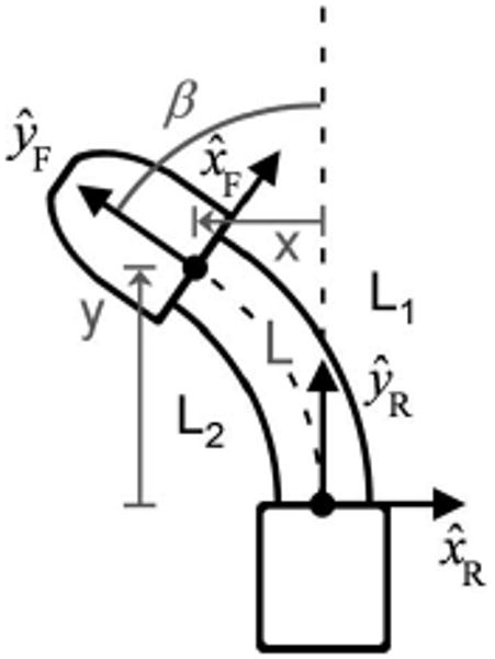
Front crawler body turning to the left, with kinematic axes and variables shown. The Cartesian location (x, y) of the front body with respect to the rear body is controlled by the wire lengths L1 and L2.
| (1) |
where 2r is the fixed distance between the drive wires.
A geometric evaluation of the Cartesian coordinates of the front body in terms of the length and bending angle of the primary backbone yields the following forward kinematics for the front-body position:
| (2) |
Combining (1) and (2) yields the forward kinematics to calculate the front-body Cartesian position (i.e., workspace variables) from the wire lengths (i.e., joint space variables)
| (3) |
This pair of equations can then be solved for the joint space variables in terms of the workspace variables, thus yielding the following closed-form inverse kinematic equations:
| (4) |
D. Locomotion Mechanics
HeartLander generates a cyclic inchworm-like gait by controlling the wire lengths between the two bodies of the robot and the vacuum pressure in the corresponding suction grippers. One cycle of the process is illustrated schematically in Fig. 9. During extension, the front body is advanced by pushing the drive wires, while the rear body is fixed to the epicardium via suction. During retraction, the rear body is advanced to meet the front body by pulling the drive wires after the suction grip has been transferred from the rear to the front body. This locomotion scheme requires that some amount of slack be maintained in the tether, and thus, the tether has been made sufficiently long. Turning is achieved by choosing a step location for the front body that has a nonzero bending angle. A maximum step length of 25 mm is used during locomotion. This value was found to allow maximum step displacement without causing the drive wires to buckle during bench testing on a plastic beating-heart model with an artificial pericardium (The Chamberlain Group, Great Barrington, MA).
Fig. 9.
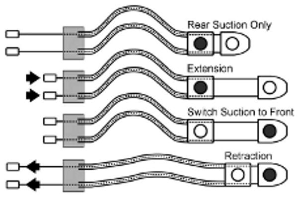
One cycle of the HeartLander crawler locomotion. The shaded circles show the active suction grippers with prehension of the epicardium. The arrows indicate the direction of wire actuation.
If the body with active suction grip of the epicardium does not slip during either the extension or retraction phases, the efficiency for the step is 100%. This would result in the robot advancing by the full step length. In the intrapericardial environment, however, the body with suction grip of the epicardium often slips somewhat, thereby resulting in a step efficiency of less than 100%.
E. Controller Design
In order to meet the different requirements of the navigation and fine-positioning components of target acquisition, the control system has two operational modes. Switching between the control modes balances the tradeoff between speed and accuracy based on the requirements of the task. The navigation mode is used to quickly deliver the robot to the general target vicinity, while the fine-positioning mode is used to precisely acquire the individual targets within the pattern. The selection of the control mode is based on the current location of the robot relative to the control boundary—the circular boundary with a radius equal to the single step length of the robot, and an origin located at the projection of the navigation target into the transverse plane of the robot (see Fig. 10). As mentioned in Section IV-B, all kinematics are considered within the transverse plane of the robot. When the robot is outside of this boundary, navigation proceeds along the path, as described in the next section, without accounting for the filtering delay in the tracking data. This allows the robot to move to the general target vicinity rapidly. The estimation error of the robot location due to the filtering delay is ignored during navigation because the target will not be acquired in this control mode, thus making position accuracy less critical.
Fig. 10.
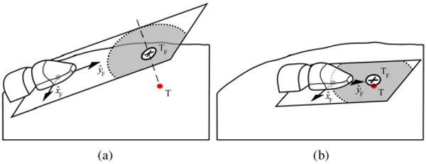
Target (T) being projected into the transverse plane of the robot during (a) navigation and (b) fine positioning. The projected target (TF) is shown by the cross, while the acceptable target-acquisition region is shown by the white circle. The concentric light gray circle shows the control-mode boundary between navigation and fine positioning.
After the robot crosses the control boundary, the control system enters the fine-positioning mode. The front body of the robot is then maneuvered directly to the current target projection using the inverse kinematics until the target is acquired within the distance specified by the surgeon. In this second control mode, the accuracy of the robot location estimation with respect to the target is critical. After each motion of the front body toward the target, the control system pauses to account for the filter delay before updating the current robot location from the tracker data. If the target is not acquired by the current motion, subsequent adjustments of the front body are made until the target is acquired within the specified distance. In this manner, the robot makes a series of fine-positioning motions, rather than full steps involving motion of the rear foot. This scheme allows the acquisition of multiple local targets in minimal time.
The semiautonomous design of the controller keeps the high-level commands under the control of the surgeon while regulating the control-mode selection, path following, and actuator commands. Both control modes proceed as long as the surgeon advances the joystick. The surgeon also currently has control over which target from the pattern is selected as the initial target for navigation, and the order of the target acquisitions in the fine-positioning mode. We believe that keeping the surgeon actively involved in the therapy planning and execution will both ease the adoption of the technology and take advantage of user expertise. Additionally, the surgeon has the option to execute hard-coded, open-loop locomotion commands (e.g., walk straight, turn left) that override the control-mode selection. These open-loop commands are available in case the surgeon desires more direct control over the actions of the robot in a particular situation.
F. Path Tracking
The path-tracking component of the navigation controller defines the manner in which the robot follows the path from the apex to the initial navigation target. Specifically, the path tracker selects an intermediate point along the path as the goal point for the current step, plans a trajectory to the goal point, and issues the corresponding actuator commands. Path tracking is accomplished using pure pursuit [45], which is widely used in mobile robot path tracking and has been shown to outperform numerous other control theory approaches and polynomial fitting approaches under various conditions [46]. Predictive [47], adaptive, and feedforward [48] variations of classical pure pursuit exist, but these more sophisticated methods deal with problems that arise in continuous high-speed applications. Simple pure pursuit is a reasonable selection for this application because HeartLander makes discrete motions at low speeds along paths with low curvature. The pure pursuit algorithm calculates the constant steering angle that delivers a car-like vehicle from its current location to the goal point [45]. This task is geometrically similar to our path-tracking task because the HeartLander crawler moves along arcs of constant curvature at each step. The goal point is selected as the intermediate point along the path that is located at a specified distance from the current robot location (see Fig. 11). This distance is called the lookahead distance, which is the single parameter that can be adjusted to modify the path-following behavior of pure pursuit. If the lookahead distance is small, the robot will tightly adhere to the path but may oscillate about curves depending on the speed of the robot. If the lookahead distance is large, on the other hand, the robot will smoothly follow the path without oscillation but may cutoff sharp corners. The value of the lookahead distance is specific to the tracking strategy and, therefore, cannot be optimized in the general case [46]. We currently set the lookahead distance to be equal to the maximum single step length, i.e., 25 mm, because we do not anticipate high path curvatures.
Fig. 11.
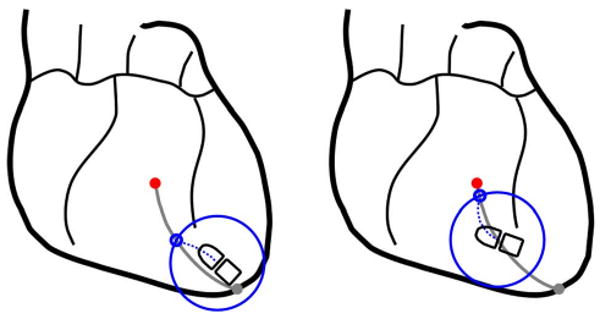
Two iterations of the pure pursuit path-tracking algorithm used by the HeartLander control system.
After the goal point has been determined, the path tracker calculates the actuator commands to generate the desired motion of the front body to the goal point. The path tracker uses the estimation of the front-body location from the filtered robot-tracking sensor to transform the goal point into the reference frame of the robot. The inverse kinematics (4) are then used to calculate the drive wire lengths between the bodies that will move the front body to the goal point. After the current step is complete, the next goal point is found, and navigation continues until the robot enters the fine-positioning control mode near the initial navigation target.
V. Experimental Protocol
This section describes the experimental protocol and specific performance metrics that are used to evaluate the navigation, fine positioning, and stability of HeartLander through a series of porcine studies.
A. Porcine Preparation
Healthy swine (N = 3; body weight 40–50 kg) were used in three porcine studies in accordance with a board-approved protocol. Porcine models were selected because they have a well-developed fibrous pericardium and extensive diaphragmatic attachments that are similar to those in humans [49]. The heart was allowed to beat naturally, without the use of antiarrhythmic drugs. The animal was placed on a ventilator, and breathing was regulated at 0.2 Hz. The surgeon accessed the apex of the heart through an incision beneath the sternum and placed HeartLander on the epicardium through a second small incision in the pericardium (see Fig. 12). This subxiphoid approach provided intrapericardial access for the robot on the beating heart without requiring differential ventilation or lung deflation. Additional clinical details can be found in [22].
Fig. 12.
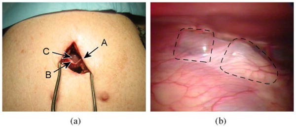
(a) Subxiphoid approach. A 30- to 40-mm skin incision (A), and 10- to 15-mm pericardial incision (B) were made to access to the epicardial surface of the apex (C). (b) HeartLander beneath the pericardium on the anterior surface of the heart. The outlines of the front and rear bodies have been highlighted with a broken line.
B. Navigation Study
The purpose of the navigation study was to quantify the ability of HeartLander to provide access to the circumference of the ventricles in a semiautonomous manner. Seven locations, spanning the circumference of the ventricles, were selected by the surgeon as the navigation targets for the study [see Fig. 4(b)]. The surgeon attempted to acquire the targets in seven separate navigation trials, each beginning near the apex of the heart. Prior to each trial, the surgeon selected the current navigation target, and placed HeartLander proximal to the apex, using the graphic display for assistance. Each navigation trial proceeded until the surgeon released the joystick or the robot acquired the navigation target. The maximum acceptable distance between the robot and the target for acquisition was selected by the surgeon to be 2.0 mm.
Following each navigation trial, the following parameters were calculated: number of steps, path length, path width, total duration, speed, and efficiency. These values were also averaged over all trials for the entire study. The tracking sensor data were low-pass filtered, as described in Section IV-B, to attenuate the physiological components of the motion. The path length was calculated as the sum of the motion toward the navigation target over all steps. Path width was calculated as the average lateral deviation of the robot from the planned path over all steps. The efficiency was calculated as sum of all step lengths normalized by the product of the commanded step length and the number of steps.
C. Fine-Positioning Study
The goal of the fine-positioning study was to evaluate the precision and speed of the semiautonomous acquisition of a clinically relevant local target pattern. Two circular target pattern acquisitions were performed on the anterior and posterior ventricular surfaces in two separate beating-heart porcine trials, each with the chest closed and pericardium intact. Fig. 4(d) shows the approximate target pattern locations on an illustration of a single porcine heart. The anterior pattern consisted of eight targets located around the perimeter of a 20-mm-diameter circle, with one target at the origin of the circle. The posterior pattern consisted of seven targets around the perimeter of a 15-mm-diameter circle, with one target at the origin. The surgeon selected the smaller pattern with fewer targets for the posterior test because the porcine heart was measured to be approximately 20% smaller than the heart used for the anterior testing. The maximum acceptable distance from the robot to the target for acquisition was set to 2.0 mm by the surgeon.
To begin each trial, the surgeon placed the target pattern at the desired ventricular location on the heart-surface model in the graphic display. The surgeon then acquired each individual target within the pattern using the semiautonomous fine-positioning control mode. With the rear body gripping the epicardium, the control system advanced the front body of crawler toward the current target until the surgeon released the joystick or the robot moved within the specified range of the target. After each target was acquired, the surgeon performed a dye injection with the front body locked onto the epicardium to both simulate injection therapy and mark the robot location on the porcine heart. After the injection was complete, the control system advanced the front body to the next target. The rear body remained fixed throughout the fine-positioning task.
In evaluating the accuracy of the HeartLander system in the fine-positioning task, we considered both the absolute and relative components of the task. As a qualitative check of absolute accuracy, we compared the position and orientation of the overall target pattern on the heart-surface model with its position and orientation on the actual porcine heart, which was photographed postoperatively. As a precise quantitative check of the relative accuracy of the system, we measured the error between each intraoperative tracker measurement and its corresponding dye mark on the porcine heart. The length of time for each target acquisition was also calculated.
D. Stability Metrics
For both the navigation study and the first fine-positioning study, we quantified the stability provided by HeartLander following target acquisition with both bodies fixed to the epicardium. Stability was assessed at each of the navigation targets (N = 7) and each of the fine-positioning targets (N = 9). The navigation targets spanned the circumference of the ventricles, while the fine-positioning targets were all located on the anterior surface of the left ventricle. Accordingly, stability was assessed over a wide range of locations on the heart. We measured stability by calculating the maximum 3-D resultant drift over a 30-s period with both bodies gripping the epicardium. This is a conservative estimation of stability because it attributes to slippage all motion that remains after low-pass filtering, whereas in reality, there exists variation in the pose of the heart between heartbeat and respiratory cycles, which this simplified method erroneously classifies as drift. The goal for stability was to maintain the maximum resultant drift below 1.5 mm over a 30-s period.
VI. Porcine Model Results
This section describes the results from the series of porcine studies designed to evaluate the navigation, fine positioning, and stability of HeartLander.
A. Subxiphoid Approach
The surgeon was able to safely deliver HeartLander to the intrapericardial space using a subxiphoid approach in all porcine studies. A 30- to 40-mm percutaneous incision was made directly below the subxiphoid process of the sternum, followed by a smaller 10- to 15-mm incision in the pericardium [see Fig. 12(a)]. This provided direct access to the epicardial surface of the apex, whereby HeartLander was placed beneath the pericardium [see Fig. 12(b)]. All animals survived until end of the procedure, at which point, they were euthanized according to the board-approved protocol. No adverse hemodynamic or electrophysiological events were noted. No significant epicardial damage was found by visual inspection or histological analyses of the excised hearts. Suction marks were visible on the epicardium but have been demonstrated to be temporary [17]. For more clinical details from the HeartLander porcine studies, see [22].
B. Navigation Results
In the navigation study, HeartLander successfully traveled from the apex of the beating porcine heart to the seven targets located around the circumference of the ventricles. During testing, the location of the robot, relative to the heart-surface model, and the current navigation path were displayed to the surgeon in real time (see Fig. 7). This allowed the surgeon to monitor the progress of the robot toward the target. As can be seen in Fig. 13, the seven navigation targets spanned the anterior, lateral, and posterior surfaces of the heart. Note that the paths were shorter on the posterior surface due to the decreased posterior lengths of the porcine ventricles. The navigation metrics for each trial, along with the averages and standard deviations for the entire study, are available in Table I. The paths averaged 38 ± 10 mm in length and 3 ± 3 mm in width. The average locomotion speed was 29 ± 13 mm/min, resulting in an average trial duration of 97 ± 58 s. The locomotion efficiency was 40 ± 15%.
Fig. 13.
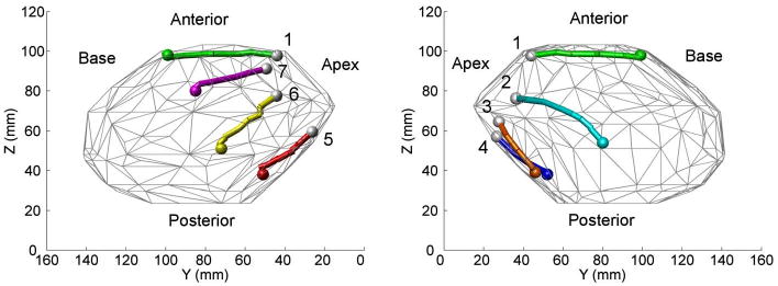
Heart-surface model showing navigation targets and the completed paths reconstructed from microBIRD data collected in vivo using a beating-heart porcine model. The seven paths illustrate coverage of the ventricles around the circumference of the heart.
TABLE I. Performance Data From Navigation Study in Porcine Model.
| Trial No. | Anatomical Location | No. Steps | Path Length (mm) |
Path Width (mm) |
Duration (s) |
Speed (mm/min) |
Efficiency (%) |
|---|---|---|---|---|---|---|---|
| 1 | Anterior Midline | 6 | 52 | 2 | 68 | 46 | 59 |
| 2 | Left Lateral | 14 | 50 | 7 | 207 | 15 | 28 |
| 3 | Left Posterior | 4 | 28 | 7 | 56 | 30 | 55 |
| 4 | Posterior Midline | 5 | 29 | 2 | 55 | 32 | 43 |
| 5 | Right Posterior | 10 | 29 | 0 | 95 | 18 | 20 |
| 6 | Right Lateral | 11 | 36 | 1 | 144 | 15 | 29 |
| 7 | Right Anterior | 6 | 39 | 3 | 54 | 44 | 49 |
| Mean ± Std | 8 ± 4 | 38 ± 10 | 3 ± 3 | 97 ± 58 | 29 ± 13 | 40 ± 15 | |
C. Fine-Positioning Acquisitions and Injections
The surgeon was able to use HeartLander to acquire all targets within the separate circular patterns on the anterior and posterior ventricular surfaces of the beating porcine heart. During testing, the surgeon relied solely on the graphic display and the data from the electromagnetic tracking system to validate that targets were acquired within the specified range of 2 mm. These values (“A → B” errors) are available in the third columns of Tables II and III for the anterior and posterior positioning trials, respectively. The target acquisitions were performed solely with motions of the front body and did not require steps to reposition the rear body. The average acquisition time for each individual target was 10 ± 5 s for the anterior pattern and 23 ± 15 s on the posterior pattern, excluding the time required for dye injection. These data are available in the last columns of Tables II and III.
TABLE II. Target-Acquisition Data From Fine-Positioning Study: Anterior Pattern.
| Target No. | Target Distance (mm) |
A→B Error (mm) |
Duration (s) |
|---|---|---|---|
| 1 | 5.0 | 1.5 | 6 |
| 2 | 10.6 | 1.2 | 7 |
| 3 | 10.6 | 0.9 | 15 |
| 4 | 18.0 | 0.9 | 17 |
| 5 | 15.0 | 1.3 | 7 |
| 6 | 18.0 | 1.1 | 11 |
| 7 | 23.1 | 0.4 | 3 |
| 8 | 23.1 | 0.8 | 15 |
| 9 | 25.0 | 0.9 | 13 |
| Mean ± Std | 16 ± 7 | 1.0 ± 0.3 | 10 ± 5 |
TABLE III. Target-Acquisition Data From Fine-Positioning Study: Posterior Pattern.
| Target No. | Target Distance (mm) |
A→B Error (mm) |
B→C Error (mm) |
C→D Error (mm) |
A→D Error (mm) |
Duration (s) |
|
|---|---|---|---|---|---|---|---|
| 1 | 5.0 | 1.0 | 1.9 | 0.4 | 1.7 | 13 | |
| 2 | 9.8 | 0.4 | 0.8 | 0.6 | 2.3 | 28 | |
| 3 | 9.8 | 1.0 | 1.0 | 0.8 | 0.9 | 23 | |
| 4 | 15.9 | 0.9 | 1.6 | 0.7 | 0.3 | 9 | |
| 5 | 12.5 | 0.3 | 1.5 | 0.1 | 1.6 | 21 | |
| 6 | 15.9 | 0.4 | 1.1 | 0.3 | 1.9 | 20 | |
| 7 | 19.5 | 1.5 | 1.0 | 3.0 | 3.6 | 56 | |
| 8 | 19.5 | 0.3 | 0.3 | 0.7 | 1.1 | 11 | |
| Mean ± Std | 14 ± 5 | 0.7 ± 0.4 | 1.1 ± 0.5 | 0.8 ± 0.9 | 1.7 ± 1.0 | 23 ± 15 | |
Following each target acquisition, the surgeon used the remote-injection system onboard HeartLander to inject 0.1 ml of oil-based dye into the heart. The dye injections were successful for 89% of the targets on the anterior pattern (eight out of nine) and 100% of the targets on the posterior pattern (eight out of eight). With the needle penetration depth set to 3 mm, the average maximum dye penetration depth was 3.0 ± 0.5 mm.
D. Absolute Positioning Accuracy
The images of the intraoperative acquisition patterns generated from the tracker measurements, along with the accompanying heart-surface models, were scaled to match a ruler that was placed alongside the excised porcine hearts in postoperative photographs and then rotated as needed to match the alignment of the dye patterns. These images are shown in Fig. 14(a) and (b) for the anterior positioning trial and in Fig. 15(a) and (b) for the posterior trial. Figs. 14(c) and 15(c) show the tracker measurement images overlaid on the photographs of the excised hearts from the anterior and posterior trials, respectively. These figures demonstrate good qualitative agreement between the geometric shapes of the heart-surface models and the excised porcine hearts and between the locations of the tracker measurements of the target acquisitions and the dye marks on the excised porcine hearts.
Fig. 14.

Anterior target acquisition pattern. (a) Excised porcine heart and dye mark pattern. (b) Scaled and aligned tracker-based heart model and planned target pattern. (c) Tracker-based heart surface and acquisition pattern overlaid on the injection photograph. The absolute location and orientation of the target pattern qualitatively agree between the tracker-based and dye-based images.
Fig. 15.
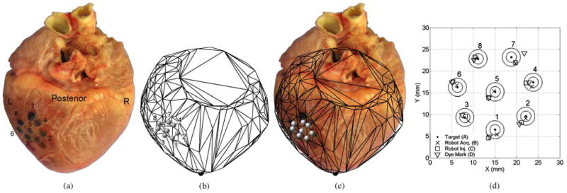
Posterior target acquisition pattern. (a) Excised porcine heart and dye mark pattern. (b) Scaled and aligned tracker-based heart model and planned target pattern. (c) Tracker-based heart surface and acquisition pattern overlaid on the injection photograph. The absolute location and orientation of the target pattern qualitatively agree between the tracker-based and dye-based images.
E. Relative Positioning Accuracy
The relative errors between the locations of the individual tracker measurements and dye marks were calculated in the assessment of the relative accuracy for the posterior positioning trial. The posterior pattern was used for this analysis because the excised heart showed that the anterior pattern had been inadvertently placed over the right and left ventricles, thereby violating one of the protocol criteria (see Section II-B). Four separate measurements of the target patterns were used in the calculation of the relative accuracy:
the planned target locations defined with respect to the electromagnetic tracking system, i.e., the goal pattern;
the tracker measurements of the robot immediately following target acquisition (front body not gripping);
the tracker measurements of the robot during dye injection (front body gripping the heart);
the dye marks visible in postoperative photographs of the excised porcine heart.
The location of the robot at each injection site was estimated as the center of the circular dye mark on the tissue, which was found in bench testing to be a valid assumption.
All tracker-based patterns and the dye mark photograph were scaled according to known distances in both images. The dye mark pattern from the photograph was aligned with the tracker-based patterns by calculating the translation and rotation that minimized the sum of root-squared distances between individual target pairs. The total relative error between each planned target location and dye mark (“A → D”) was the cumulative error between the planned target and the robot tracker at the target acquisition (“A → B”), the robot tracker at the target acquisition and at the dye injection (“B → C”), and the robot tracker at the dye injection and the physical dye mark on the heart tissue (“C → D”). All errors were calculated as the 2-D resultant distances between the individual targets in the aligned images, were reported individually, and averaged over all targets. The 2-D locations of all four sets of targets (A–D) can be seen in Fig. 15(d), while Table III shows the individual and averaged error values. The average total relative error (A → D) was 1.7 ± 1.0 mm.
F. Adherence Stability Results
Stability of epicardial station-keeping was estimated by measuring the maximum 3-D resultant drift of the robot for 30 s following target acquisitions in the navigation and fine-positioning studies. Fig. 16 shows the raw tracker data from the robot while gripping the heart, and the residual filtered motion that is attributed to slippage of HeartLander over the epicardium. For the navigation target acquisitions (N = 7), the average maximum resultant drift was 0.6 ± 0.1 mm. For the fine-positioning target acquisitions (N = 9), the average maximum resultant drift increased to 0.9 ± 0.5 mm. The stability data from all trials can be found in Table IV.
Fig. 16.
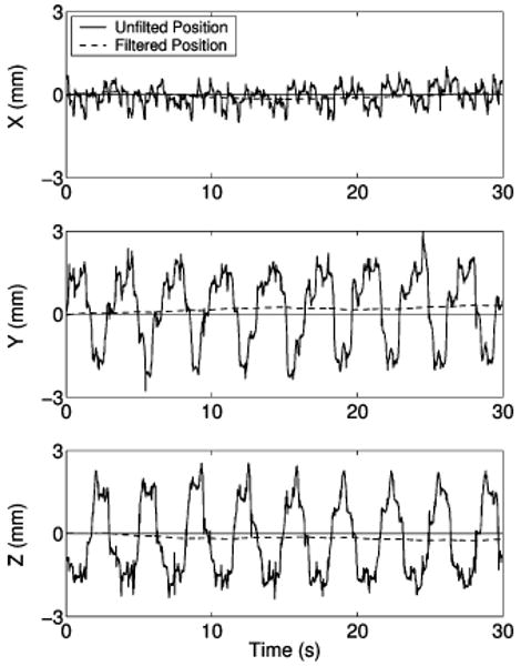
Plots showing the x-, y-, and z-components of the motion measured by the tracking sensor when the robot is stationary and fixed to the heart with both suction grippers. The raw data are shown by the solid line and the filtered drift data by the broken line.
TABLE IV. Adherence Stability Data From Studies in Porcine Models.
| Target No. | Navigation Study | Fine-Positioning Study | ||
|---|---|---|---|---|
| Anatomical Location | Drift (mm) |
Anatomical Location | Drift (mm) |
|
| 1 | Anterior midline | 0.7 | Left Lateral | 0.3 |
| 2 | Left lateral | 0.3 | Left Lateral | 0.3 |
| 3 | Left posterior | 0.7 | Left Lateral | 0.9 |
| 4 | Posterior midline | 0.5 | Left Lateral | 0.4 |
| 5 | Right posterior | 0.5 | Left Lateral | 1.0 |
| 6 | Right lateral | 0.6 | Left Lateral | 1.3 |
| 7 | Right anterior | 0.6 | Left Lateral | 1.7 |
| 8 | Left Lateral | 1.0 | ||
| 9 | Left Lateral | 1.0 | ||
| Mean ± Std | 0.6 ± 0.1 | 0.9 ± 0.5 | ||
VII. Discussion
HeartLander was designed to provide precise and stable access to the epicardial surface of the beating heart through a minimally invasive subxiphoid approach. The miniature mobile robot travels to specified targets in a semiautonomous fashion while maintaining prehension of the beating heart surface. This novel paradigm addresses the physiological motions, access limitations, and access morbidity that adversely affect intercostal robotic endoscopy for cardiac surgery. The tethered design of the robot allows the functionality of powerful offboard motors and pumps to be transmitted to the miniature crawling portion of the robot in a manner that facilitates navigation in the challenging intrapericardial environment. The control system combines user input from a joystick with tracking sensor data from the robot to enable semiautonomous target acquisition on the epicardium. The results reported in this paper from a series of porcine studies illustrate the feasibility of this concept in vivo.
The navigation study demonstrated the ability of HeartLander to provide access around the circumference of the heart in a precise, semiautonomous, and stable fashion. The navigation path lengths were approximately 50 mm on the anterior surface of the heart and 30 mm on the posterior. These lengths indicate that the navigation trials adequately spanned the lengths of the anterior and posterior ventricles. The even distribution of the navigation targets over the anterior, lateral, and posterior ventricular surfaces illustrates the utility of HeartLander to provide general access around the entire circumference of the heart. Although the average locomotion efficiency was only 40% due to slippage of the stationary crawler bodies during extension and retraction, the navigation targets were acquired within an average of 97 s. This duration is reasonable considering that, in general, no more than ten navigation trials will be required for the intrapericardial therapies envisioned for HeartLander. Future research will focus on improving locomotion efficiency by synchronizing the locomotion phase with heartbeat and respiration. The path planning and tracking of the navigation control system will also be enhanced in the future to accommodate the labeling of certain anatomical regions of the diseased heart as obstacles that must be avoided.
HeartLander also demonstrated semiautonomous acquisition of specified target patterns, followed by dye injections, on the anterior and posterior surfaces of beating porcine hearts through a subxiphoid approach with no adverse physiological events. It is noteworthy that surgeons have some difficulty in accessing the posterior surface of the beating heart, even under full sternotomy. The average acquisition time for each target in the pattern, excluding the time for dye injection, was 10 s for the anterior trial and 23 s for the posterior trial. The increased acquisition time for the posterior positioning trial was caused by two factors: the increase in required accuracy specified in the control system by the surgeon and the increased difficulty of maneuvering beneath the heart. In the future, it will be beneficial to explore the tradeoff between the required targeting accuracy and the resulting acquisition speed. The dye injections were successful at 94% of the anterior and posterior targets (16 out of 17). This was evaluated by examining the dye marks on the excised heart surface and making incisions into the dye locations to measure the penetration depth. We hypothesize that the failed injection may have been due to insufficient penetration of the needle into the heart tissue, which will be addressed in future designs of the remote injection system.
The absolute accuracy of the positioning system was found to be qualitatively good on both the anterior and posterior surfaces of the beating heart. The tracker measurements of the robot location were in good agreement with the dye marks on the photograph of the excised porcine heart. Additionally, the contours of heart-surface models used in the graphic display were in good agreement with those of the excised hearts. This validates that the heart-surface model serves as a geometric representation of the heart surface that agrees with the surface of the true porcine heart. It also validates the use of the surface model and electromagnetic tracking system to identify the general anatomical location of the robot on the true heart. We were unable to measure the absolute accuracy of the positioning system due to the lack of anatomical information on the graphic display, which makes it impossible to determine the absolute locations of the tracker-based targets on the physical heart. Accordingly, the integration of preoperative imaging will be an aspect of future research for the HeartLander project.
The total relative accuracy of the HeartLander positioning system was measured to be 1.7 mm on the posterior surface of the beating heart, which is below the goal of 2.0 mm. To the authors' knowledge, these results represent the most accurate positioning that has been achieved on the posterior epicardial surface of the beating heart when accessed by a minimally invasive approach. The initial component of the relative error (A → B), which was used by the control system as the real-time distance from robot to the target, was measured to be 0.7 mm. The next component of the relative error (B → C) was due to the displacement of the robot after gripping the moving epicardium and was measured to be 1.1 mm. The values of these relative errors are available to the control system during testing and can, therefore, be reduced with improvements to the control system. The component of the relative error between the robot tracker measurements at dye injection and the physical dye marks on the excised heart (C → D) may have resulted from the reported static inaccuracy of the electromagnetic tracking system (1.4 mm) or from uneven distribution of the dye into the myocardium. This issue must be explored in future work. The unusually large error associated with target 7 in the posterior testing could have been due to such an uneven distribution of the dye into the myocardium, thereby leading us to misjudge the location of the front body during dye injection.
The stability provided by HeartLander following target acquisition on the anterior, lateral, and posterior regions of the ventricles was shown to be greater than that of commercial mechanical stabilizers used in surgery, which exhibit 1.5–2.4 mm of residual motion [11], [12]. The goal for epicardial stability was to keep the maximum resultant drift of the robot below 1.5 mm for a period of 30 s with both bodies fixed to the epicardium. The average 3-D drifts during the navigation and fine-positioning studies were 0.6 and 0.9 mm, respectively, which were below the target threshold in both cases. Although the stability calculation method presented in this paper did filter out the regular periodic heartbeat motion from the drift measure, it did not account for the positional variability of the heart from beat to beat. Accordingly, the reported measure of drift is likely an overestimate. For the aforementioned intrapericardial therapies, we do not believe that this submillimeter level of drift will adversely affect procedure outcomes. Nevertheless, we will attempt to reduce the magnitude of drift by adding coatings to the upper surface of the HeartLander crawler to reduce the friction forces imparted by the shearing between the epicardium and pericardium. Additionally, we can measure the drift in real time with the tracking sensor and compensate for it using active control.
In order to transform HeartLander into a clinically useful device many improvements must be made to the current system. In the near future, HeartLander will be equipped with onboard diagnostic sensors to provide local measurements prior to treatment and validation following treatment. These measurements can also be used to generate a map of physiological properties over the heart surface. In this manner, HeartLander will become a diagnostic, as well as therapeutic, tool. In a recent preliminary study, we measured the activation times at several locations on the heart surface using a customized bipolar electrode located on the bottom of HeartLander. Additionally, high-quality preoperative imaging, such as computerized tomography or magnetic resonance imaging, must be integrated into the graphic display. When properly registered, this will allow the surgeon to see details, such as the coronary arteries, on the real-time display that also shows the current location of the robot. It should also be emphasized that although we have demonstrated several therapeutic applications from HeartLander—epicardial injections, pacing lead placement, and ablation—these were feasibility studies that did not produce a clinical result in the animal models.
The results reported in this paper illustrate the ability of the HeartLander robotic system to provide precise, stable, semiautonomous access to the epicardial surface of the beating heart through a subxiphoid approach. In the future, HeartLander will be further developed into a clinical device that provides intrapericardial access, diagnosis, therapy, and evaluation—potentially on an outpatient basis. The availability of such a device may motivate cardiac surgeons to further explore the intrapericardial frontier for treatment of various heart diseases.
Acknowledgments
The authors are grateful to Dr. D. Schwartzman, K. Ng, and P. Allen for their contributions to this research.
This work was supported in part by the National Institutes of Health under Grant R01 HL078839, in part by the National Aeronautics and Space Administration under Grant NNG05GL63H, and in part by the National Science Foundation under Grant EEC-9731748.
Biographies

Nicholas A. Patronik received the B.S. degree in biomedical engineering from Boston University, Boston, MA, in 2000 and the Ph.D. degree in robotics from Carnegie Mellon University, Pittsburgh, PA, in 2008.
He is currently a Senior Research Scientist with St. Jude Medical, St. Paul, MN.

Takeyoshi Ota received the M.D. and Ph.D. degrees from Kobe University, Kobe, Japan, in 1999 and 2005, respectively.
Since 2005, he has been with the Division of Cardiac Surgery, University of Pittsburgh, Pittsburgh, PA. His current research interests include minimally invasive robotic cardiac surgery, tissue-engineered cardiac structures, and extracellular matrices.

Marco A. Zenati received the B.S. degree from the Liceo Scientifico “Girolamo Fracastoro,” Verona, Italy, in 1980 and the M.D. degree from the University of Verona, in 1986.
He is currently a Professor of surgery and bioengineering with the University of Pittsburgh School of Medicine, Pittsburgh, PA, and an Adjunct Faculty with the Robotics Institute of Carnegie Mellon University, Pittsburgh. In 2000, he performed the first robotic coronary bypass surgery on the beating heart in the U.S. at the University of Pittsburgh Medical Center Presbyterian Hospital. He has authored or coauthored more than 250 peer-reviewed papers and books on cardiovascular medicine.
Prof. Zenati is the recipient of the Philip Caves Award for “outstanding contributions to the field of heart failure research” from the International Society for Heart and Lung Transplantation and of the Alexis Carrel International Award by transplant pioneer Christiaan Barnard.

Cameron N. Riviere (S'94–M'95) received the B.S. degree in aerospace and ocean engineering from the Virginia Polytechnic Institute and State University, Blacksburg, in 1989 and the Ph.D. degree in mechanical engineering from the Johns Hopkins University, Baltimore, MD, in 1995.
Since 1995, he has been with the Robotics Institute, Carnegie Mellon University, Pittsburgh, PA, where he is currently an Associate Research Professor. His current research interests include medical robotics, control systems, signal processing, learning algorithms, and human–machine interfaces for biomedical applications, including surgery and rehabilitation.
Prof. Riviere is an Associate Editor on the Conference Editorial Board of the IEEE Engineering in Medicine and Biology Society and was one of the Guest Editors of the special issue on medical robotics of the Proceedings of the IEEE in 2006.
Contributor Information
Nicholas A. Patronik, Email: patronik@alumni.cmu.edu, N. A. Patronik was with the Robotics Institute, Carnegie Mellon University, Pittsburgh, PA 15213 USA. He is now with St. Jude Medical, St. Paul, MN 55117 USA.
Takeyoshi Ota, Email: otat@upmc.edu, Division of Cardiac Surgery, University of Pittsburgh, Pittsburgh, PA 15213 USA.
Marco A. Zenati, Email: zenatim@upmc.edu, Division of Cardiac Surgery, University of Pittsburgh, Pittsburgh, PA 15213 USA.
Cameron N. Riviere, Email: camr@ri.cmu.edu, Robotics Institute, Carnegie Mellon University, Pittsburgh, PA 15213 USA.
References
- 1.Kim VB, Chapman WH, Albrecht RJ, Bailey BM, Young JA, Nifong LW, Chitwood WR., Jr Early experience with telemanipulative robot-assisted laparoscopic cholecystectomy using da Vinci. Surg Laparosc Endosc Percutan Tech. 2002 Feb.12:33–40. doi: 10.1097/00129689-200202000-00006. [DOI] [PubMed] [Google Scholar]
- 2.Ficarra V, Cavalleri S, Novara G, Aragona M, Artibani W. Evidence from robot-assisted laparoscopic radical prostatectomy: A systematic review. Eur Urol. 2007 Jan.51:45–56. doi: 10.1016/j.eururo.2006.06.017. [DOI] [PubMed] [Google Scholar]
- 3.Ascione R, Lloyd CT, Underwood MJ, Lotto AA, Pitsis AA, Angelini GD. Inflammatory response after coronary revascularization with or without cardiopulmonary bypass. Ann Thorac Surg. 2000 Apr.69:1198–204. doi: 10.1016/s0003-4975(00)01152-8. [DOI] [PubMed] [Google Scholar]
- 4.Mack MJ. Minimally invasive and robotic surgery. J Amer Med Assoc. 2001 Feb.285:568–572. doi: 10.1001/jama.285.5.568. [DOI] [PubMed] [Google Scholar]
- 5.Dzwonczyk R, del Rio CL, Sai-Sudhakar C, Sirak JH, Michler RE, Sun B, Kelbick N, Howie MB. Vacuum-assisted apical suction devices induce passive electrical changes consistent with myocardial ischemia during off-pump coronary artery bypass graft surgery. Eur J Cardiothorac Surg. 2006 Dec.30:873–876. doi: 10.1016/j.ejcts.2006.09.005. [DOI] [PubMed] [Google Scholar]
- 6.Falk V, Diegler A, Walther T, Autschbach R, Mohr FW. Developments in robotic cardiac surgery. Curr Opin Cardiol. 2000 Nov.15:378–387. doi: 10.1097/00001573-200011000-00002. [DOI] [PubMed] [Google Scholar]
- 7.Kinjo S, Tokumine J, Sugahara K, Kakinohana M, Iha K, Matsuda H, Akasaki M, Yamashiro S. Unexpected hemodynamic deterioration and mitral regurgitation due to a tissue stabilizer during left anterior descending coronary anastomosis in off-pump coronary artery bypass graft surgery. Ann Thorac Cardiovasc Surg. 2005 Oct.11:324–328. [PubMed] [Google Scholar]
- 8.Lemma M, Mangini A, Redaelli A, Acocella F. Do cardiac stabilizers really stabilize? Experimental quantitative analysis of mechanical stabilization. Interact Cardiovasc Thorac Surg. 2005 Jun.4:222–226. doi: 10.1510/icvts.2004.098517. [DOI] [PubMed] [Google Scholar]
- 9.Koransky ML, Tavana ML, Yamaguchi A, Kown MH, Miniati DN, Nowlin W, Robbins RC. Quantification of mechanical stabilization for the performance of off-pump coronary artery surgery. Heart Surg Forum. 2003;6:224–231. [PubMed] [Google Scholar]
- 10.Bachta W, Renaud P, Laroche E, Gangloff J, Forgione A. Cardiolock: An active cardiac stabilizer. First in vivo experiments using a new robotized device. Proc Int Conf Med Image Comput Comput Assist Interv. 2007;10:78–85. [PubMed] [Google Scholar]
- 11.Cattin P, Dave H, Grunenfelder J, Szekely G, Turina M, Zund G. Trajectory of coronary motion and its significance in robotic motion cancellation. Eur J Cardiothorac Surg. 2004 May;25:786–790. doi: 10.1016/j.ejcts.2004.01.019. [DOI] [PubMed] [Google Scholar]
- 12.Bebek O, Cavusoglu MC. Intelligent control algorithms for robotic-assisted beating heart surgery. IEEE Trans Robot. 2007 Jun.23(3):468–480. [Google Scholar]
- 13.Gangloff J, Ginhoux R, de Mathelin M, Soler L, Marescaux J. Model predictive control for compensation of cyclic organ motions in teleoperated laparoscopic surgery. IEEE Trans Control Syst Technol. 2006 Mar.14(2):235–246. [Google Scholar]
- 14.Ginhoux R, Gangloff J, de Mathelin M, Soler L, Sanchez MMA, Marescaux J. Active filtering of physiological motion in robotized surgery using predictive control. IEEE Trans Robot. 2005 Feb.21(1):67–79. [Google Scholar]
- 15.Ortmaier T, Groeger M, Boehm DH, Falk V, Hirzinger G. Motion estimation in beating heart surgery. IEEE Trans Biomed Eng. 2005 Oct.52(10):1729–1740. doi: 10.1109/TBME.2005.855716. [DOI] [PubMed] [Google Scholar]
- 16.Hoksch B, Birken-Bertsch H, Muller JM. Thoracoscopy before Jacobaeus. Ann Thorac Surg. 2002 Oct.74:1288–1290. doi: 10.1016/s0003-4975(02)03676-7. [DOI] [PubMed] [Google Scholar]
- 17.Borst C, Jansen EW, Tulleken CA, Grundeman PF, Beck HJM, van Dongen JW, Hodde KC, Bredee JJ. Coronary artery bypass grafting without cardiopulmonary bypass and without interruption of native coronary flow using a novel anastomosis site restraining device (“Octopus”) J Amer Coll Cardiol. 1996 May;27:1356–1364. doi: 10.1016/0735-1097(96)00039-3. [DOI] [PubMed] [Google Scholar]
- 18.Jansen EW, Lahpor JR, Borst C, Grundeman PF, Bredee JJ. Off-pump coronary bypass grafting: how to use the Octopus Tissue Stabilizer. Ann Thorac Surg. 1998 Aug.66:576–579. doi: 10.1016/s0003-4975(98)00477-9. [DOI] [PubMed] [Google Scholar]
- 19.Patronik NA, Zenati MA, Riviere CN. Preliminary evaluation of a mobile robotic device for navigation and intervention on the beating heart. Comput Aided Surg. 2005 Jul.10:225–232. doi: 10.3109/10929080500230197. [DOI] [PubMed] [Google Scholar]
- 20.Zenati MA, Bonanomi G, Chin AK, Schwartzman D. Left heart pacing lead implantation using subxiphoid videopericardioscopy. J Cardiovasc Electrophysiol. 2003 Sep.14:949–953. doi: 10.1046/j.1540-8167.2003.03255.x. [DOI] [PubMed] [Google Scholar]
- 21.Soejima K, Couper G, Cooper JM, Sapp JL, Epstein LM, Stevenson WG. Subxiphoid surgical approach for epicardial catheter-based mapping and ablation in patients with prior cardiac surgery or difficult pericardial access. Circulation. 2004 Sep. 7110:1197–1201. doi: 10.1161/01.CIR.0000140725.42845.90. [DOI] [PubMed] [Google Scholar]
- 22.Ota T, Patronik NA, Schwartzman D, Riviere CN, Zenati MA. Minimally invasive epicardial injections using a novel semiautonomous robotic device. Circulation. 2008;118:S115–S120. doi: 10.1161/CIRCULATIONAHA.107.756049. [DOI] [PMC free article] [PubMed] [Google Scholar]
- 23.Ota T, Patronik NA, Schwartzman D, Riviere CN, Zenati MA. Subxiphoid epicardial pacing lead implantation using a miniature crawling robotic device. J Surg Res. 2007;137:242–243. [Google Scholar]
- 24.Dario P, Ciarletta P, Menciassi A, Kim B. Modeling and experimental validation of the locomotion of endoscopic robots in the colon. Int J Robot Res. 2004;23:549–556. [Google Scholar]
- 25.Hirose S. Biologically Inspired Robots: Snake-Like Locomotors and Manipulators. New York: Oxford Univ Press; 1993. [Google Scholar]
- 26.Kim B, Lee MG, Lee YP, Kim Y, Lee G. An earthworm-like micro robot using shape memory alloy actuator. Sens Actuators A: Phys. 2006;125:429–437. [Google Scholar]
- 27.Iddan G, Meron G, Glukhovsky A, Swain P. Wireless capsule endoscopy. Nature. 2000 May 25;405:417. doi: 10.1038/35013140. [DOI] [PubMed] [Google Scholar]
- 28.Uehara A, Hoshina K. Capsule endoscope NORIKA system. Minim Invasive Ther Allied Technol. 2003 Sep.12:227–234. doi: 10.1080/13645700310014933. [DOI] [PubMed] [Google Scholar]
- 29.Kusuda Y. A further step beyond wireless capsule endoscopy. Sens Rev. 2005;25:259–260. [Google Scholar]
- 30.Stefanini C, Menciassi A, Dario P. Modeling and experiments on a legged microrobot locomoting in a tubular, compliant and slippery environment. Int J Robot Res. 2006;25:551–560. [Google Scholar]
- 31.Rentschler ME, Dumpert J, Platt SR, Iagnemma K, Oleynikov D, Farritor SM. Modeling, analysis, and experimental study of in vivo wheeled robotic mobility. IEEE Trans Robot. 2006 Apr.22(2):308–321. [Google Scholar]
- 32.Chun JK, Ernst S, Matthews S, Schmidt B, Bansch D, Boczor S, Ujeyl A, Antz M, Ouyang F, Kuck KH. Remote-controlled catheter ablation of accessory pathways: Results from the magnetic laboratory. Eur Heart J. 2007 Jan.28:190–195. doi: 10.1093/eurheartj/ehl447. [DOI] [PubMed] [Google Scholar]
- 33.Reddy VY, Neuzil P, Malchano ZJ, Vijaykumar R, Cury R, Abbara S, Weichet J, McPherson CD, Ruskin JN. View-synchronized robotic image-guided therapy for atrial fibrillation ablation: experimental validation and clinical feasibility. Circulation. 2007 May;115:2705–2714. doi: 10.1161/CIRCULATIONAHA.106.677369. [DOI] [PubMed] [Google Scholar]
- 34.Patronik N, Ota T, Zenati MA, Riviere CN. Accurate positioning for intervention on the beating heart using a crawling robot. Proc 2nd IEEE RAS/EMBS Int Conf Biomed Robot Biomechatron. 2008:250–257. [Google Scholar]
- 35.Santamore WP, Constantinescu MS, Bogen D, Johnston WE. Nonuniform distribution of normal pericardial fluid. Basic Res Cardiol. 1990 Nov./Dec.85:541–549. doi: 10.1007/BF01907889. [DOI] [PubMed] [Google Scholar]
- 36.Shechter G, Resar JR, McVeigh ER. Displacement and velocity of the coronary arteries: Cardiac and respiratory motion. IEEE Trans Med Imag. 2006 Mar.25(3):369–375. doi: 10.1109/TMI.2005.862752. [DOI] [PMC free article] [PubMed] [Google Scholar]
- 37.Kocher AA, Schuster MD, Szabolcs MJ, Takuma S, Burkhoff D, Wang J, Homma S, Edwards NM, Itescu S. Neovascularization of ischemic myocardium by human bone-marrow-derived angioblasts prevents cardiomyocyte apoptosis, reduces remodeling and improves cardiac function. Nat Med. 2001 Apr.7:430–436. doi: 10.1038/86498. [DOI] [PubMed] [Google Scholar]
- 38.Rivero-Ayerza M, Theuns DA, Garcia-Garcia HM, Boersma E, Simoons M, Jordaens LJ. Effects of cardiac resynchronization therapy on overall mortality and mode of death: A meta-analysis of randomized controlled trials. Eur Heart J. 2006 Nov.27:2682–2688. doi: 10.1093/eurheartj/ehl203. [DOI] [PubMed] [Google Scholar]
- 39.Schweikert RA, Saliba WI, Tomassoni G, Marrouche NF, Cole CR, Dresing TJ, Tchou PJ, Bash D, Beheiry S, Lam C, Kanagaratnam L, Natale A. Percutaneous pericardial instrumentation for endo-epicardial mapping of previously failed ablations. Circulation. 2003 Sep.108:1329–1335. doi: 10.1161/01.CIR.0000087407.53326.31. [DOI] [PubMed] [Google Scholar]
- 40.Kirklin JW, Kouchoukos NT. Kirklin/Barratt-Boyes Cardiac Surgery: Morphology, Diagnostic Criteria, Natural History, Techniques, Results, and Indications. 3rd. Philadelphia, PA: Churchill Livingstone; 2003. [Google Scholar]
- 41.Gravagne IA, Rahn CD, Walker ID. Large deflection dynamics and control for planar continuum robots. IEEE/ASME Trans Mechatron. 2003 Jun.8(2):299–307. [Google Scholar]
- 42.Patronik NA, Ota T, Zenati MA, Riviere CN. Improved traction for a mobile robot traveling on the heart. Proc 28th Annu Int Conf IEEE Eng Med Biol Soc. 2006:339–342. doi: 10.1109/IEMBS.2006.259532. [DOI] [PubMed] [Google Scholar]
- 43.Schneider M, Stevens C. Development and testing of a new magnetic-tracking device for image guidance. Prog Biomed Opt Imag. 2007;8:1–11. [Google Scholar]
- 44.Lessick J, Sideman S, Azhari H, Shapiro E, Weiss JL, Beyar R. Evaluation of regional load in acute ischemia by three-dimensional curvatures analysis of the left ventricle. Ann Biomed Eng. 1993 Mar./Apr.21:147–161. doi: 10.1007/BF02367610. [DOI] [PubMed] [Google Scholar]
- 45.Coulter RC. Implementation of the pure pursuit path tracking algorithm. Robot Inst, Carnegie Mellon Univ, Tech Rep CMU-RI-TR-92-01. 1992 [Google Scholar]
- 46.Amidi O. Integrated mobile robot control. Robot Inst, Carnegie Mellon Univ, Tech Rep CMU-RI-TR-90-17. 1990 [Google Scholar]
- 47.Ollero A, Amidi O. Predictive path tracking of mobile robots. Proc 5th Int Conf Adv Robot. 1991;2:1081–1086. [Google Scholar]
- 48.Kelly A. A feedforward control approach to the local navigation problem for autonomous vehicles. Robot Inst, Carnegie Mellon Univ, Tech Rep CMU-RI-TR-94-17. 1994 [Google Scholar]
- 49.Shabetai R. The Pericardium. 2nd. Boston, MA: Kluwer; 2003. [Google Scholar]


