Abstract
Tissue engineered skeletal muscle has tremendous potential for the treatment of muscular injury or muscular dysfunction. However, in vitro methods to generate skeletal muscle with physiologically aligned myofiber structure remains limited. To develop a robust in vitro model that resembles the physiologically aligned structure of muscle fibers, we fabricated micropatterned polymer membranes of poly(dimethylsiloxane) (PDMS) with parallel microgrooves, and then examined the effect of micropatterning on myoblast cellular organization and the cell fusion process. In comparison to the myoblasts on non-patterned PDMS films, myoblasts on micropatterned PDMS films had well-organized F-actin assembly in close proximity to the direction of microgrooves, along with enhanced levels of myotube formation at early time points. The increase of cell cycle regulator p21WAF/Cip1 and the organized interactions of N-cadherin in myoblasts on micropatterned surfaces may contribute to the enhanced formation of myotubes. Similar results of cellular alignment was observed when myoblasts were cultured on microfluidically patterned poly(2-hydroxyethyl methacrylate) (pHEMA) microgrooves, and the micropatterns were found to detach from the Petri dish over time. To apply this technology for generating aligned tissue-like muscle constructs, we developed a methodology to transfer the aligned myotubes to biodegradable collagen gels. Histological analysis revealed the persistence of aligned cellular organization in the collagen gels. Together, these results demonstrate that micropatterned PDMS or pHEMA can promote cell alignment and fusion along the direction of the microgrooves, and this platform can be utilized to transfer aligned myotubes on biodegradable hydrogels. This study highlights the importance of spatial cues in creating aligned skeletal muscle for tissue engineering and muscular regeneration applications.
Keywords: Micropatterning, myoblast, skeletal muscle, tissue engineering, fusion, alignment
Introduction
Tissue engineered skeletal muscle has tremendous potential for the treatment of muscular injury or muscular dysfunction (e.g. muscular dystrophy). The engineered muscles can be used for delivering genes and proteins to surrounding tissues. In addition to therapeutic applications, engineered muscles provide a platform for studying the molecular mechanisms of muscle morphogenesis. The fundamental strategy in creating bioengineered skeletal muscles is to mimic the structure, composition, and function of muscular tissue. Skeletal muscle is composed of aligned bundles of fibers formed by the fusion of myoblasts into multi-nucleated myotubes [1]. When cultured in vitro, however, the anatomical structure is lost such that myoblasts grow in a randomly oriented fashion.
In order to mimic the highly organized structure of skeletal muscle in vitro, various approaches have been taken. For example, Powell et al. created human bioartificial muscles by culturing skeletal muscle cells in a collagen/matrigel matrix before subjecting the construct to repetitive mechanical stimulation, resulting in parallel arrangements of myofibers [2]. Another approach to create oriented myofibers involves culturing skeletal myoblasts on polymer microfibers that form parallel arrays [3]. More recently, aligned muscular networks have been generated by aligned nanofibrous scaffolds and micromolding of myoblasts in hydrogels [4-6].
Here we describe the use of micropatterning technology for engineering parallel aligned myoblasts and myotubes. Microfabrication using soft lithography is a technique that can topographically pattern surface structures or chemically pattern the surface with matrix proteins and growth factors in a highly reproducible manner [7, 8]. We and others have shown that micropatterned surfaces control many aspects of cellular behavior, including spatial organization, migration, proliferation, and survival [5, 9-19]. This approach not only can be used to engineer muscles in vitro on flexible scaffold materials, but it also provides a valuable in vitro model to investigate the response of myoblasts to spatial cues.
In this study, we cultured myoblasts on micropatterned microgrooves of poly(dimethylsiloxane) (PDMS), an optically translucent and elastic material that provides a deformable substrate for cell traction [20], and examined the effect of micropattterned features on myoblast cellular organization and cell fusion. We then developed a method to transfer the aligned myotubes into collagen hydrogel to generate tissue-like constructs with aligned cellular organization. Our results show that micropatterned surfaces regulate the orientation of myoblast cell alignment and enhance the fusion of myoblasts into myotubes, but have no significant effect on the expression of contractile markers at mRNA and protein level. Similar results of cellular alignment were observed when myoblasts were cultured on microfluidically patterned poly(2-hydroxyethyl methacrylate) (pHEMA) substrates. Using micropatterning technology, we also show that aligned cellular organization could be maintained when transferred into collagen gels for the formation of three-dimensional tissue-like constructs.
Materials and methods
Polymer characterization
Polymer mechanical properties were assessed by an Instron (Model 5566, Canton, MA) machine at a strain rate of 20% per minute. Young's Modulus, tensile strength, and elongation to break measurements were quantified and expressed as mean ± standard deviation (n=3).
Microfabrication of PDMS substrates
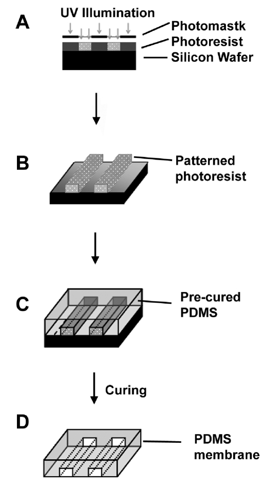
Micropatterned films composed of PDMS polymer was fabricated from a silicon wafer inverse template according to Huang et al. [5] (Figure 1). Briefly, a mask with patterned emulsion strips was first generated. The parallel strips were 10-μm wide, 10-μm apart, and 4-cm in length. To transfer the pattern to the silicon wafer, I-line (Arch Chemicals, Norwalk, CT) photoresist was spun onto the wafers at 820 RPM for one minute, producing a 3-μm thick layer. The wafer was then baked at 90°C for 60 seconds to harden the photoresist, before exposing the photoresist to UV Light with a KS Aligner (Karl Suss, MJB3, Germany). A post-exposure bake was performed for 60 seconds at 120°C, followed by one minute development using a photoresist developer solution OPD 4262. The wafer with unexposed photoresist was placed into the primer oven for 15 minutes at 120°C to allow the remaining photoresist to set. At this point, the wafers were ready to be used for the preparation of PDMS films.
Figure 1.
Fabrication of Micropatterned PDMS Films. (A) A negative photoresist was spincoated on silicon wafer and exposed to UV light through a photomask. (B) Photoresist without UV-polymerization was washed away, leaving a patterned surface. (C) PDMS was cast onto the wafer, spin-coated, and allowed to polymerize. (D) The cured films were then peeled away from the silicon wafer.
Micropatterned and non-patterned PDMS films were prepared as directed by the manufacturer (Sylgard 184, Dow Corning, MI) using a 9:1 ratio by mass of the prepolymer to crosslinker. After degassing under vacuum, 15 g of PDMS was poured onto the wafer and spun to create a uniform layer approximately 350- μm thick. The wafer with PDMS was heated at 80°C for 60 minutes to allow polymerization of PDMS. After the fabrication process, the PDMS membranes were removed from the wafer and cleaned by sonication in water. The dimensions of the final micropatterned features were 10-μm wide, 10-μm apart, 3-μgm deep, and 4 cm in length. To sterilize and promote cell adhesion, the membranes were pretreated with oxygen plasma and coated with 2% gelatin for 30 minutes before cell seeding.
Micropatterning of poly (2-hydroxyethyl methacrylate) (pHEMA)
Micropatterning of detachable microgrooves was carried out by using pHEMA, a hydrophobic synthetic polymer capable of inhibiting cell adhesion and spreading. As inverse templates, PDMS molds containing parallel microgrooves 50-μm wide, 50-μm apart, 50-μm deep, and 4-cm long were adhered to Petri dishes, and 3% pHEMA dissolved in 95% ethanol was introduced to the microgrooves by vacuum at the channel outlet. Ethanol in the microgrooves was allowed to evaporate overnight before removing the PDMS mold to reveal pHEMA microgrooves. The microgrooves hindered cell attachment, thereby forcing cells to selectively attach to areas on the surface between the pHEMA microgrooves. The samples were sterilized by UV before cell culture experiments.
Myoblast culture on micropatterned substrates
Murine C2C12 myoblasts (ATCC, Manassas, VA) were cultured in growth media that consisted of Dulbecco's Modified Eagle's Medium (DMEM), 10% fetal bovine serum and 1% penicillin/streptomycin. Myoblasts were seeded to 100% confluency onto the substrates. To initiate myoblast differentiation, the growth media was replaced with differentiation media that consisted of DMEM, 5% horse serum and 1% penicillin/streptomycin after 24 hours when samples were confluent. Cells cultured on non-patterned substrates were used as controls. In all experiments, time points were denoted by the incubation time in differentiation media. Samples were imaged on a Nikon TE300 microscope with a Hammatsu CCD camera to monitor cell growth.
Generation of aligned muscle-like constructs in collagen gel
After 7 days in differentiation media, the aligned myotubes on pHEMA-patterned substrates were transferred to collagen gel to generate muscle-like constructs. To do so, the cells were overlaid by a thin layer of 1 mg/ml rat tail collagen I (BD Biosciences, Bedford, MA) containing 10% FBS, 1% penicillin/streptomycin, and DMEM. The gel was incubated at 37 °C for 1 hour for solidification before overlaying additional differentiation media. After 3 days of culture, during which myotubes migrated into the collagen gel, the gel was rolled around a biodegradable tubular mandrel composed of poly(lactide co-caprolactone co-glycolide) (PLCG, Sigma) having dimensions 4 cm in length and 0.8 cm in diameter. The gel was rolled around the mandrel up to 5 turns, forming a multi-layered muscle-like construct. The muscle-like constructs were submerged in Optimal Cutting Temperature (OCT) embedding medium (Sakura, Torrance, CA) for routine cryosectioning and hematoxylin and eosin (H&E) staining analysis.
Immunofluorescent staining
Samples were fixed in 4% paraformaldehyde, permeabilized with 0.5% Triton X-100, and pretreated with 1% bovine serum albumin (BSA). Samples were incubated with anti-skeletal fast myosin (Sigma) or anti-N-cadherin primary antibodies, followed by the incubation with fluorescein (FITC)-conjugated secondary antibodies (Jackson ImmunoResearch, West Grove, PA). F-actin assembly was stained using FITC-conjugated phalloidin (Molecular Probes, Eugene, OR). For staining of myosin heavy chain (MHC), samples were incubated with mouse anti-skeletal fast MHC (Sigma, St. Louis, MO), followed by the incubation with FITC-conjugated donkey anti-mouse (Jackson ImmunoResearch, West Grove, PA) secondary antibody. Cell nuclei were stained with ToPro (Molecular Probes) before visualizing with a Nikon TE300 microscope or Leica TCS SL confocal microscope. Confocal images represent two-dimensional projections of three-dimensional stacked images.
To analyze cell alignment and fusion, immunofluorescent images of anti-skeletal MHC staining were taken under at least 5 representative high-power (40X) and low-power (10X) fields. Using SPOT 4.0.5 software (Diagnostic Instruments, Sterling Heights, MI), myotube alignment in reference to the axis of the microgrooves was quantified and plotted in the form of a distribution curve. The minimum myotube alignment value of 0° denoted parallel alignment from the axis of the microgrooves and the maximum of 90° represented perpendicular alignment. For alignment analysis of non-patterned PDMS substrates, an arbitrary axis of alignment was used. In addition to this method of analysis for cell alignment, the two-dimensional Fast Fourier Transform (2D FFT) approach was also used for quantitative assessment of alignment. 2D FFT analysis was performed by an Image J plugin, as described previously [21]. Besides cell alignment, the percentage of nuclei incorporated into myotubes was assessed on both micropatterned and non-patterned substrates. All data was expressed as mean ± standard deviation (n=3). Statistical significance was calculated by a student's t-test for two groups or analysis of variance (ANOVA) with Holm's adjustment for multiple comparisons.
RNA isolation and quantitative polymerase chain reaction (qPCR)
RNA isolation and qPCR was carried out according to Park et al. [22]. Briefly, the cells were lysed in RNA Stat-60 (Tel-Test, Friendswood, TX), and the RNA was extracted by chloroform and phenol, followed by isopropanol precipitation. Two-step Reverse Transcription Polymerase Chain Reaction (RT-PCR) was performed using the ThermoScript RT-PCR system for first strand cDNA synthesis (Invitrogen, Carlsbad, CA). Equal loading of cDNA was used for qPCR (ABI Prism 7000 Sequence Detection System (Applied Biosystems, Foster City, CA). Primers for qPCR were designed by using ABI Prism Primer Express software (Applied Biosystems) and can be found in Table 1. Each gene was normalized by 18S RNA and expressed as a ratio of gene quantities on the micropatterned substrate, relative to the non-patterned substrate (n=3). Statistical significance for gene expression data was quantified by a log-transformed one sample t-test [23].
Table 1.
Primers used in qPCR
| Gene Name | Forward Primer (5' to 3') | Reverse Primer (3' to 5') |
|---|---|---|
| β-actin | TTCCTTCTTGGGTATGGAATCCT | TGTGTTGGCATAGAGGTCTTTACG |
| Mylc2b | GCAGCATCAGGTCAGATTTAAACC | GCGCTTCTTGGTGGTCTTG |
| Tpm1 | GGAGCAAGCAGCTGGAAGAT | CCTCGGAGTATTTGTCCAGTTCA |
| Tnnc1 | CAAAGCTGCGGTAGAACAGTTG | CGCCCAAGACAAAGATATCAAAG |
| Tnnt1 | ACGCCCAGAAATTCCGAAA | GTCCTGGCAGTCTCACTTCCA |
| Ttn | CACAACATACAGGGTAAAAGGTCTCA | GGCCCTGCCAAATTTTCAG |
| 18S | CATTCTTGGCAAATGC TTTCG | GCCGCTAGAGGTGAAATTCTTG |
Immunoblotting
Immunoblotting procedure was carried out according to Park et al. [22]. Briefly, cell lysates (20 μg from each sample) were separated by sodium dodecyl sulfate-polyacrylamide gel electrophoresis (SDS-PAGE) under reducing conditions and transferred to nitrocellulose membranes. Membranes were incubated with primary antibodies against α-actin (Sigma), p21WAF/Cip1 (Santa Cruz Biotechnology), or extracellular signal-regulated kinase 2 (ERK2, Santa Cruz Biotechnology), followed by the incubation with the secondary antibody conjugated with horseradish peroxidase (Santa Cruz Biotechnology). Proteins were then visualized by an ECL Detection system (Amersham Biosciences, Piscataway, NJ) and normalized to the abundance of α-tubulin (Santa Cruz Biotechnology) (n=3).
Results
Polymer characterization
To determine the mechanical property of PDMS polymer, we performed experiments to assess Young's Modulus, tensile strength, and elongation to break. PDMS was characterized by a Young's Modulus of 5.0 ± 0.1 MPa, tensile strength of 15.1 ± 3.6 MPa, and elongation to break of 156.5 ± 23.3%. Compared to brittle or hard materials that have high Young's Modulus (e.g. 10–20 GPa for bone) [24] and low-yield elongation [25], PDMS was an elastic material that could sustain mechanical loads. The mechanical properties are similar to other polymers with tissue engineering applications, such as biodegradable copolymers containing poly(lactide-co-glycolide) (PLGA) and poly(ε-caprolactone) (PCL) [26].
Cellular organization
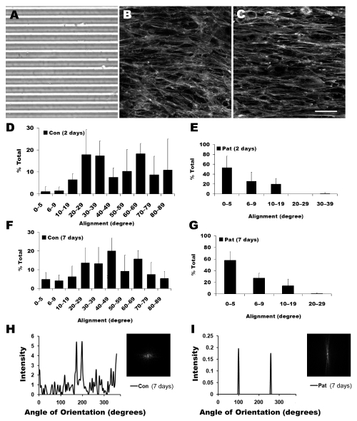
PDMS microgrooves were fabricated with high reproducibility according to bright-field microscopy images (Figure 2A). To examine the cell organization on non-patterned and micropatterned substrates, samples were immunofluorescently stained with phalloidin for F-actin. After 2 days in differentiation media, the F-actin stress fibers appeared disorganized on the non-patterned substrate (Figure 2B). In stark contrast, the stress fibers aligned within close proximity to the orientation of the channels (Figure 2C) on the micropatterned substrate.
Figure 2.
Alignment of differentiating myoblasts on micropatterned substrates. A. Bright field image of PDMS micropatterns. Immunofluorescent staining of F-actin assembly on (B) non-patterned (control) and (C) micropatterned substrates. Quantification of myotube orientation on control and micropatterned substrates after 2 days (D and E, respectively) and 7 days (F and G, respectively). After 7 days in differentiation media, cell alignment was also quantified by 2D FFT analysis and depicted by alignment plots on non-patterned (H) or micropatterned (I) substrates. Insets represent corresponding frequency plots. Scale bar, 50 μm.
To quantify the distribution and level of cell alignment, samples were stained with MHC, a marker for mature differentiated myofibers [27, 28]. The degree of alignment was defined as the angle formed with the axis of the channels such that an angle of 0° corresponded to perfect alignment. For cells cultured on the non-patterned substrate, the cell orientation was randomly distributed from 0–90° after 2 days in differentiation media (Figure 2D). In stark contrast, the cell orientation on micropatterned PDMS was preferentially restricted within 20° relative to the direction of the microgrooves after 2 days (Figure 2E). The cell alignment persisted at day 7, as cells on non-patterned substrates remained randomly oriented (Figure 2F), whereas on the micropatterned substrate the alignment remained restricted to within 20° (Figure 2G). Notably, greater than 50% of the cell alignments were within 5° at both 2 days and 7 days on the micropatterned substrate. In addition, striations were more frequently observed in myotubes on micropatterned substrates than non-patterned substrates. These results confirmed that the micropattern could maintain cell alignment for prolonged culture period (at least 7 days).
The cell alignment distribution on non-patterned or micropatterned substrates was also characterized by 2D FFT analysis, which converts spatial information into mathematically defined optical data. This data was depicted by a frequency alignment histogram and a frequency plot. The frequency plot consisted of grayscale pixels that were distributed in patterns around the origin that reflect the degree of cell alignment. As shown in Figure 2H-I, representative frequency alignment maps showed the principal angle of orientation of the myotubes in 360° of space. The level of cellular alignment was depicted by the height and overall shape of the peaks [29]. The alignment histogram of the myotubes on non-patterned substrates consisted generally of many low frequency peaks, which are characteristic of randomly oriented myotubes. This data was also depicted by the 2D FFT frequency plot (Figure 2H inset), which showed a symmetric distribution of spots about the center. In contrast to that on the non-patterned substrate, the alignment histogram for the micropatterned substrate consisted of two distinctive peaks (Figure 2I) that were 180° apart, which suggests highly organized myotubes. The presence of two peaks instead of one reflects geometric symmetry due to the summation of angles from 0 to 360° rather than a summation from 0 to 180°. The highly oriented myotube alignments were further depicted by the 2D FFT frequency plot (Figure 2I inset), which contained pixels concentrated along a specific axis. Therefore, the 2D FFT analysis verified the high degree of aligned myotubes on non-patterned substrates, in contrast to myotubes on non-patterned substrates.
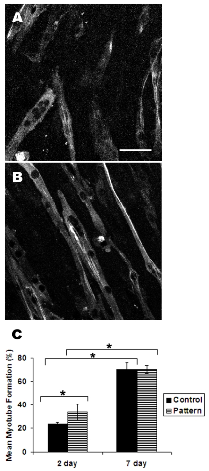
In addition to cell alignment, the level of myoblast fusion into myotubes was also assessed by the incorporation of cell nuclei into MHC-expressing multi-nucleated myotubes. In comparison between non-patterned and patterned PDMS films at 2 days of differentiation, 34 ± 7% of the total cell nuclei were found in myotubes on micropatterned substrates, whereas the corresponding value was significantly lower at 23 ± 1% (P<0.05) (Figure 3A-B). This result indicated that the micropatterned substrate could enhance myotube formation after 2 days of differentiation. However, the mean myotube formation after 7 days was at comparable levels of 70 ± 3% on the micropatterned substrate and 70 ± 6% on the non-patterned substrate (Figure 3C). Although the levels of myotube incorporation increased significantly from 2 days to 7 days for each substrate (P<0.05), the micropatterned substrate could enhance the incorporation of myoblasts into myotubes at the early stages of cell fusion.
Figure 3.
Myotube formation on micropatterned substrates. After 2 days of incubation in differrentiation media, control non-patterned (A) and micropatterned (B) samples were immunofluorescently stained for myosin heavy chain to visualize myotubes. The average percent of nuclei incorporated into myotubes was assessed. * indicate statistically significant comparisons (P<0.05). Scale bar, 50 μm.
Gene and protein expression
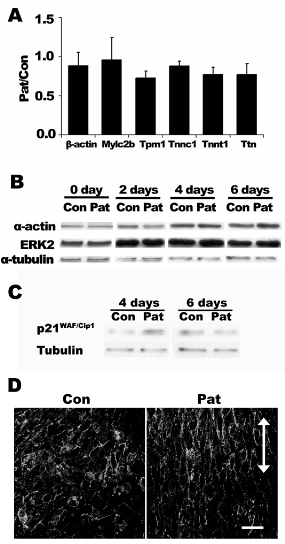
To elucidate how micropatterned substrate affects myoblast fusion at early time points, we analyzed the gene and protein expression of various markers involved in myoblast differentiation after 2 days. At the level of gene expression, qPCR results showed that the relative ratios of muscle markers troponin-C, troponin-T, titin, tropomyosin-1, myosin light chain regulatory b, and β-actin were not significantly different between the cells on micropatterned and non-patterned PDMS substrates (Figure 4A). At protein level, the time course of myoblast differentiation showed a gradual increase of ERK2 and β-actin. On both non-patterned and micropatterned surfaces, cytoskeletal markers α-actin peaked after 4 days. The protein expression of ERK2, which has been shown to regulate skeletal myogenesis [30], peaked after 2 days. However, the expression levels of these proteins did not vary significantly between non-patterned and micropatterned substrates. These findings suggest that micropatterned substrates did not significantly affect cytoskeletal markers at the transcriptional or protein level.
Figure 4.
Expression of contractile, cell-cell adhesion, and cell cycle markers on micropatterned and non-patterned PDMS substrate. (A) Normalized gene expression for β-actin, myosin light chain regulatory b (mylc2b), tropomyosin-1 (tpm1), troponin-C (tnnc1), troponin-T (tnnt1), and titin (Ttn) between micropatterned (Pat) and non-patterned (Con) PDMS substrates after 2 days in differentiation media. Data is expressed as the relative ratio of Pat/Con. (B) Representative immunoblot expression time course for α-actin and ERK2 during myoblast fusion. (C) Representative immunoblot expression of p21WAF/Cip1 during myoblast fusion. (D) Immunofluorescence staining depicting N-cadherin organization on non-patterned and micropatterned substrates after 2 days of differentiation. Scale bar, 50 μm. Arrow indicates the direction of microgrooves.
In contrast to the differential effects of ERK2 and β-actin on micropatterned substrates, the expression of cell cycle inhibitor, p21WAF/Cip1, appeared to be higher on the micropatterned substrate than control substrate after 4 days in differentiation media before reaching similar expression levels after 6 days (Figure 4C). These results suggest that micropatterned substrates could promote myoblast withdrawal from the cell cycle by upregulating p21WAF/Cip1 at early timepoints. In addition, N-cadherin, which is an important regulator of cell shape and myoblast fusion [31-33], was more notably organized along the direction of the micropatterned grooves, compared to the random orientation in the non-patterned substrate (Figure 4D). These results suggest that cell cycle and cell-cell adhesion molecules may play a role in modulating myoblast fusion.
Microfluidic patterning of pHEMA microgrooves
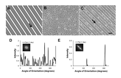
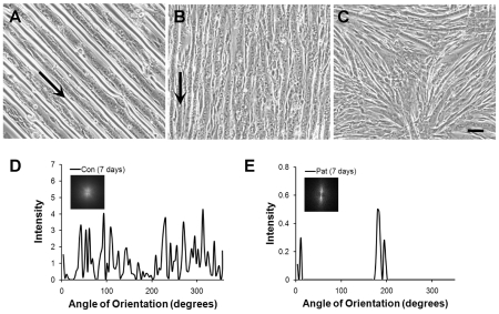
To apply the micropatterning platform for substrates to culture dishes, we used PDMS stamps as inverse templates to microfluidically pattern microgrooves of pHEMA onto Petri dishes. As shown by phase contrast microscopy, the microgrooves of pHEMA were optically transparent and uniformly deposited onto the Petri dish (Figure 5A). When myoblasts were cultured in growth media for one day, the cells on non-patterned Petri dishes were randomly distributed (Figure 5B). In contrast, cells on microfluidically patterned Petri dishes preferentially adhered to the Petri dish, but not on the pHEMA microgrooves (Figure 5C), and the cells oriented themselves in the direction of the microgroove direction. As shown by the 2D FFT alignment plots and frequency plots, the cells remained randomly distributed on the non-patterned substrate (Figure 5D), whereas the cells were highly aligned on cells on micropatterned pHEMA microgrooves (Figure 5E). During the course of one week in differentiation media, the detachment of pHEMA from the Petri dish was apparent after 4 days (Figure 6A). After 7 days, the pHEMA microgrooves were no longer present and were replaced by aligned myotubes (Figure 6B). On the other hand, myotubes formed on non-patterned Petri dishes remained randomly oriented (Figure 6C). Similar to the 2D FFT alignment plots and frequency plots after 1 day, the myotubes after 7 days in differentiation media remained randomly distributed on the non-patterned substrate (Figure 6D), whereas the cells were highly aligned on cells on micropatterned pHEMA microgrooves (Figure 6E). This data suggests a similar cell alignment profile on pHEMA microgrooves as on PDMS substrates. Furthermore, our results demonstrated a novel method to generate aligned myotubes on a tissue culture Petri dish using non-adherent pHEMA microgrooves, which could later be removed.
Figure 5.
Alignment of myoblasts on Petri dishes patterned by pHEMA microgrooves. A. Phase contrast image shows microfluidic patterning of pHEMA microgrooves. Myoblasts on non-patterned (B) substrates show random orientation after 1 day of culture, whereas myoblasts on micropatterned substrates (C) selectively grow on the Petri dish with aligned orientation. Cell alignment was quantified by FFT analysis and depicted by alignment plots on non-patterned (D) or micropatterned (E) substrates. Insets represent corresponding circular frequency plots. Arrows denote location and orientation of pHEMA microgrooves. Scale bar, 100 μm.
Figure 6.
Fusion of myoblasts on Petri dishes patterned by pHEMA microgrooves. A. Phase contrast image shows fusion of myoblasts on micropatterned substrates after 4 days in differentiation media. B. After 7 days in differentation media, the pHEMA microgrooves dissolve away, leaving aligned myotubes. C. In contrast, myotubes formed on non-patterned substrates show random orientation after 7 day of culture. Cell alignment was quantified by FFT analysis and depicted by alignment plots on non-patterned (D) or micropatterned (E) substrates. Insets represent corresponding circular frequency plots. Arrows denote orientation of pHEMA microgrooves. Scale bar, 100 μm.
Generation of aligned muscle-like constructs in collagen gel
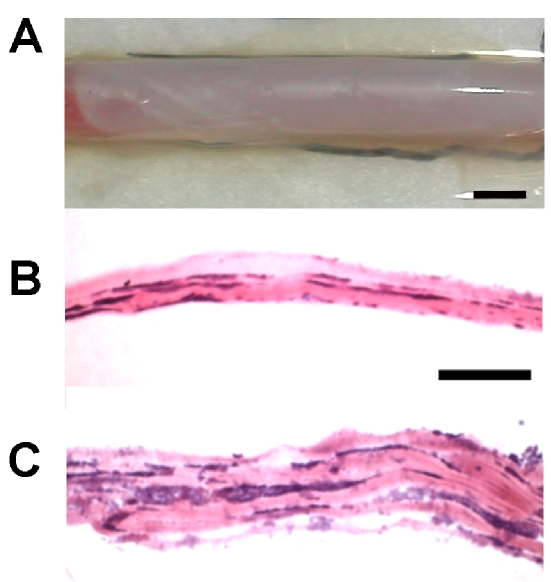
To apply micropatterning tools for tissue engineering applications, we developed a method to transfer the aligned myotubes from rigid Petri dishes to soft biodegradable collagen gels. Utilizing samples of aligned myotubes formed on pHEMA microgrooves for 7 days (at which pHEMA microgrooves have detached), collagen gel was overlaid on the cells for 3 days, during which the cells migrated into the collagen gel. The cell-seeded collagen gel was then rolled around a biodegradable PLCG polymer mandrel to generate a tubular muscle-like construct (Figure 7A) consisting of many layers (Figure 7B-C). Figure 7B illustrates a gel containing 3 layers, whereas Figure 7C depicts a rolled gel containing up to 5 layers. The muscle layers appeared to be integrated in that the multiple layers of the construct could stick together upon being rolled up in the absence of additional support. Collagen was present in the construct, but it is likely that the myotubes in adjacent layers would interact with each other upon complete degradation of collagen. Histological assessment demonstrated that the cells appeared viable and retained their aligned orientation in the 3- layered and 5-layered gels. This data demonstrated a novel approach to transfer aligned muscle sheets to collagen gel to generate three-dimensional aligned muscle-like constructs.
Figure 7.
Three-dimensional muscle construct in collagen gel. A. Cell and collagen gel construct rolled around a polymer mandrel. B-C. Hematoxylin and eosin staining of cross sections showing myotubes embedded into collagen gel. Scale bars: A, 0.5 cm; B-C, 100 μm.
Discussion
In this study, we have shown that micropatterned substrates can regulate myoblast organization, myotube formation, and F-actin assembly. The parallel microgrooves of PDMS effectively aligned the myotubes within 20° from the direction of the microgrooves, in agreement with previous reports [5, 34, 35]. Moreover, our data shows that micropatterned topography can control myoblast morphogenesis into aligned myotubes. On micropatterned PDMS, the myoblasts attached and fused into myotubes that aligned in close proximity to the direction of the channels. After two days in differentiation media, the percentage of nuclei that incorporated into myotubes on micropatterned PDMS was significantly higher when compared to non-patterned surfaces, suggesting that micropatterned substrates could enhance myotube formation at early time points. However, the enhancement of myotube incorporation on micropatterned substrates did not appear to be modulated by contractile markers, since the mRNA and protein levels of contractile markers were not significantly different between the two groups.
On the other hand, the differential organization of N-cadherin may account for differences in the fusion process on micropatterned substrates. The extracellular domain of N-cadherin mediates cell-cell adhesion through homophilic interactions, whereas the cytoplasmic domain interacts with catenins to anchor to actin filaments [36, 37]. In previous studies, the role of N-cadherin in myogenesis was demonstrated by the inhibition of myoblast fusion in the presence of N-cadherin antibodies [38], whereas forced expression of N-cadherin in fibroblast-like cells stimulated myogenic protein expression [39]. It is likely that the organization of N-cadherin may influence cell-cell adhesion and actin assembly among myoblasts and thereby regulate the fusion process. In addition to cell-cell adhesion, the increase of p21WAF/Cip1 could arrest cell cycle and facilitate myoblast differentiation and fusion.
The micropatterned substrates were designed to incorporate features that may be important for in vitro muscle formation. As a flexible elastomer, PDMS can be stretched to simulate the mechanically loaded muscle environment in vivo [40]. Furthermore, unlike glass substrates, PDMS is deformable, but have tensile strength to withstand dynamic loading environments in vivo. The spacing between microgrooves were selected to be 10- to 50- μm wide based on our experience that myoblast alignment decreases with increasing groove width (>100 μm; data not shown), and this finding is supported by observations from other researchers [41]. Since micropatterned surfaces resemble the in vivo cellular arrangement better than non-patterned substrates, they can be useful for studying myogenesis or engineering aligned muscle for muscle repair. Furthermore, as inverse templates, the PDMS can be used to deposit pHEMA microgrooves onto Petri dishes or biological substrates such as polymer films.
Besides direct culture on micropatterned PDMS, we showed that pHEMA microgrooves could also efficiently control myoblast orientation and generate aligned myotubes. Since the pHEMA microgrooves were found to detach over time, this approach has useful applications for engineering aligned myotubes with limited dwelling time of the biomaterial. The utilization of microfabrication techniques for temporary spatial guidance has also been demonstrated by others. For example, Lam et al. formed aligned myotubes on micropatterned PDMS before transferring the aligned myotubes onto fibrin hydrogels, generating aligned skeletal muscle hydrogel constructs [4].
In addition to myoblasts, microfabrication techniques have been applied to other cell types. In our previous work using adhesive matrix micropatterning as well as topographical patterning, we showed that vascular smooth muscle cells undergo morphological and phenotypic changes in vitro [17]. On collagen-patterned glass slides, as well as on topographically patterned PLGA polymer films, smooth muscle cells decreased in spreading area, proliferation, and actin fiber assembly. On microgrooves, cardiac myocytes aligned in the direction of the microgrooves and expressed connexin-43 and N-cadherin around the cell perimeter [42]. Embryonic neurons exhibited a differential response to micropatterning such that neuronal processes extended in parallel to the grooves when cultured on deep and wide channels, while on reduced dimensions, neuronal process were directed either in parallel or perpendicular to the axis of the grooves [43]. These studies provide evidence of an association between surface topography and cellular response among numerous types of cells.
In summary, we have demonstrated that micropatterned PDMS or pHEMA can promote cell alignment and fusion along the direction of the microgrooves, and this platform can be utilized to transfer aligned myotubes on biodegradable hydrogels. The results from this study highlight the importance of spatial cues in creating aligned skeletal muscle for tissue engineering and muscular regeneration applications.
Acknowledgments
The authors thank Pui L. Leong, Nikhil Gupta, Rahul G. Thakar, Kyle Kurpinski, and Julia Chu for technical assistance. This research was supported in part by research grants from the National Institutes of Health (HL078534) and the University of California Berkeley Research Fund to S.L, and the Nora Eccles Treadwell Foundation to R.L. N.H. was supported by a fellowship from the National Science Foundation.
References
- 1.Wigmore PM, Dunglison GF. The generation of fiber diversity during myogenesis. Int J Dev Biol. 1998;42:117–125. [PubMed] [Google Scholar]
- 2.Powell CA, Smiley BL, Mills J, et al. Mechanical stimulation improves tissue-engineered human skeletal muscle. Am J Physiol Cell Physiol. 2002;283:C1557–1565. doi: 10.1152/ajpcell.00595.2001. [DOI] [PubMed] [Google Scholar]
- 3.Neumann T, Hauschka SD, Sanders JE. Tissue engineering of skeletal muscle using polymer fiber arrays. Tissue Eng. 2003;9:995–1003. doi: 10.1089/107632703322495637. [DOI] [PubMed] [Google Scholar]
- 4.Lam MT, Huang YC, Birla RK, et al. Microfeature guided skeletal muscle tissue engineering for highly organized 3-dimensional free-standing constructs. Biomaterials. 2009;30:1150–1155. doi: 10.1016/j.biomaterials.2008.11.014. [DOI] [PubMed] [Google Scholar]
- 5.Huang NF, Patel S, Thakar RG, et al. Myotube assembly on nanofibrous and micropatterned polymers. Nano Lett. 2006;6:537–542. doi: 10.1021/nl060060o. [DOI] [PubMed] [Google Scholar]
- 6.Bian W, Bursac N. Engineered skeletal muscle tissue networks with controllable architecture. Biomaterials. 2009;30:1401–1412. doi: 10.1016/j.biomaterials.2008.11.015. [DOI] [PMC free article] [PubMed] [Google Scholar]
- 7.Dow JA, Clark P, Connolly P, et al. Novel methods for the guidance and monitoring of single cells and simple networks in culture. J Cell Sci Suppl. 1987;8:55–79. doi: 10.1242/jcs.1987.supplement_8.4. [DOI] [PubMed] [Google Scholar]
- 8.Kane RS, Takayama S, Ostuni E, et al. Patterning proteins and cells using soft lithography. Biomaterials. 1999;20:2363–2376. doi: 10.1016/s0142-9612(99)00165-9. [DOI] [PubMed] [Google Scholar]
- 9.Chen CS, Mrksich M, Huang S, et al. Geometric control of cell life and death. Science. 1997;276:1425–1428. doi: 10.1126/science.276.5317.1425. [DOI] [PubMed] [Google Scholar]
- 10.Bhatia SN, Balis UJ, Yarmush ML, et al. Effect of cell-cell interactions in preservation of cellular phenotype: cocultivation of hepatocytes and nonparenchymal cells. Faseb J. 1999;13:1883–1900. doi: 10.1096/fasebj.13.14.1883. [DOI] [PubMed] [Google Scholar]
- 11.Folch A, Toner M. Microengineering of cellular interactions. Annu Rev Biomed Eng. 2000;2:227–256. doi: 10.1146/annurev.bioeng.2.1.227. [DOI] [PubMed] [Google Scholar]
- 12.Wang JH, Grood ES. The strain magnitude and contact guidance determine orientation response of fibroblasts to cyclic substrate strains. Connect Tissue Res. 2000;41:29–36. doi: 10.3109/03008200009005639. [DOI] [PubMed] [Google Scholar]
- 13.Wang JH, Grood ES, Florer J, et al. Alignment and proliferation of MC3T3-E1 osteoblasts in microgrooved silicone substrata subjected to cyclic stretching. J Biomech. 2000;33:729–735. doi: 10.1016/s0021-9290(00)00013-0. [DOI] [PubMed] [Google Scholar]
- 14.Deutsch J, Motlagh D, Russell B, et al. Fabrication of microtextured membranes for cardiac myocyte attachment and orientation. J Biomed Mater Res. 2000;53:267–275. doi: 10.1002/(sici)1097-4636(2000)53:3<267::aid-jbm12>3.0.co;2-j. [DOI] [PubMed] [Google Scholar]
- 15.Motlagh D, Senyo SE, Desai TA, et al. Microtextured substrata alter gene expression, protein localization and the shape of cardiac myocytes. Biomaterials. 2003;24:2463–2476. doi: 10.1016/s0142-9612(02)00644-0. [DOI] [PubMed] [Google Scholar]
- 16.Li S, Bhatia S, Hu YL, et al. Effects of morphological patterning on endothelial cell migration. Biorheology. 2001;38:101–108. [PubMed] [Google Scholar]
- 17.Thakar RG, Ho F, Huang NF, et al. Regulation of vascular smooth muscle cells by micropatterning. Biochem Biophys Res Commun. 2003;307:883–890. doi: 10.1016/s0006-291x(03)01285-3. [DOI] [PubMed] [Google Scholar]
- 18.Huang NF, Thakar RG, Wong M, et al. Tissue engineering of muscle on micropatterned polymer films. Conf Proc IEEE Eng Med Biol Soc. 2004;7:4966–4969. doi: 10.1109/IEMBS.2004.1404373. [DOI] [PubMed] [Google Scholar]
- 19.Shimizu K, Fujita H, Nagamori E. Alignment of skeletal muscle myoblasts and myotubes using linear micropatterned surfaces ground with abrasives. Biotechnol Bioeng. 2009;103:631–638. doi: 10.1002/bit.22268. [DOI] [PubMed] [Google Scholar]
- 20.Wang N, Ostuni E, Whitesides GM, et al. Micropatterning tractional forces in living cells. Cell Motil Cytoskeleton. 2002;52:97–106. doi: 10.1002/cm.10037. [DOI] [PubMed] [Google Scholar]
- 21.Ayres CE, Jha BS, Meredith H, et al. Measuring fiber alignment in electrospun scaffolds: a user's guide to the 2D fast Fourier transform approach. J Biomater Sci Polym Ed. 2008;19:603–621. doi: 10.1163/156856208784089643. [DOI] [PubMed] [Google Scholar]
- 22.Park JS, Chu JS, Cheng C, et al. Differential effects of equiaxial and uniaxial strain on mesenchymal stem cells. Biotechnol Bioeng. 2004;88:359–368. doi: 10.1002/bit.20250. [DOI] [PubMed] [Google Scholar]
- 23.Kurpinski K, Chu J, Hashi C, et al. Anisotropic mechanosensing by mesenchymal stem cells. Proc Natl Acad Sci U S A. 2006;103:16095–16100. doi: 10.1073/pnas.0604182103. [DOI] [PMC free article] [PubMed] [Google Scholar]
- 24.Middleton JC, Tipton AJ. Synthetic biodegradable polymers as orthopedic devices. Biomaterials. 2000;21:2335–2346. doi: 10.1016/s0142-9612(00)00101-0. [DOI] [PubMed] [Google Scholar]
- 25.Agrawal CM, Ray RB. Biodegradable polymeric scaffolds for musculoskeletal tissue engineering. J Biomed Mater Res. 2001;55:141–150. doi: 10.1002/1097-4636(200105)55:2<141::aid-jbm1000>3.0.co;2-j. [DOI] [PubMed] [Google Scholar]
- 26.Choi SH, Park TG. Synthesis and characterization of elastic PLGA/PCL/PLGA tri-block copolymers. J Biomater Sci Polym Ed. 2002;13:1163–1173. doi: 10.1163/156856202320813864. [DOI] [PubMed] [Google Scholar]
- 27.Murry CE, Wiseman RW, Schwartz SM, et al. Skeletal myoblast transplantation for repair of myocardial necrosis. J Clin Invest. 1996;98:2512–2523. doi: 10.1172/JCI119070. [DOI] [PMC free article] [PubMed] [Google Scholar]
- 28.Havenith MG, Visser R, Schrijvers-van Schendel JM, et al. Muscle fiber typing in routinely processed skeletal muscle with monoclonal antibodies. Histochemistry. 1990;93:497–499. doi: 10.1007/BF00266407. [DOI] [PubMed] [Google Scholar]
- 29.Ayres C, Bowlin GL, Henderson SC, et al. Modulation of anisotropy in electrospun tissue-engineering scaffolds: Analysis of fiber alignment by the fast Fourier transform. Biomaterials. 2006;27:5524–5534. doi: 10.1016/j.biomaterials.2006.06.014. [DOI] [PMC free article] [PubMed] [Google Scholar]
- 30.Li J, Johnson SE. ERK2 is required for efficient terminal differentiation of skeletal myoblasts. Biochem Biophys Res Commun. 2006;345:1425–1433. doi: 10.1016/j.bbrc.2006.05.051. [DOI] [PubMed] [Google Scholar]
- 31.Gavard J, Marthiens V, Monnet C, et al. N-cadherin activation substitutes for the cell contact control in cell cycle arrest and myogenic differentiation: involvement of p120 and beta-catenin. J Biol Chem. 2004;279:36795–36802. doi: 10.1074/jbc.M401705200. [DOI] [PubMed] [Google Scholar]
- 32.Yap AS, Brieher WM, Gumbiner BM. Molecular and functional analysis of cadherin-based adherens junctions. Annu Rev Cell Dev Biol. 1997;13:119–146. doi: 10.1146/annurev.cellbio.13.1.119. [DOI] [PubMed] [Google Scholar]
- 33.Mege RM, Goudou D, Diaz C, et al. N-cadherin and N-CAM in myoblast fusion: compared localisation and effect of blockade by peptides and antibodies. J Cell Sci. 1992;103(Pt 4):897–906. doi: 10.1242/jcs.103.4.897. [DOI] [PubMed] [Google Scholar]
- 34.Lam MT, Sim S, Zhu X, et al. The effect of continuous wavy micropatterns on silicone substrates on the alignment of skeletal muscle myoblasts and myotubes. Biomaterials. 2006;27:4340–4347. doi: 10.1016/j.biomaterials.2006.04.012. [DOI] [PubMed] [Google Scholar]
- 35.Clark P, Coles D, Peckham M. Preferential adhesion to and survival on patterned laminin organizes myogenesis in vitro. Exp Cell Res. 1997;230:275–283. doi: 10.1006/excr.1996.3429. [DOI] [PubMed] [Google Scholar]
- 36.Yap AS, Brieher WM, Pruschy M, et al. Lateral clustering of the adhesive ectodomain: a fundamental determinant of cadherin function. Curr Biol. 1997;7:308–315. doi: 10.1016/s0960-9822(06)00154-0. [DOI] [PubMed] [Google Scholar]
- 37.Takeichi M. Cadherin cell adhesion receptors as a morphogenetic regulator. Science. 1991;251:1451–1455. doi: 10.1126/science.2006419. [DOI] [PubMed] [Google Scholar]
- 38.Knudsen KA, Myers L, McElwee SA. A role for the Ca2(+)-dependent adhesion molecule, N-cadherin, in myoblast interaction during myogenesis. Exp Cell Res. 1990;188:175–184. doi: 10.1016/0014-4827(90)90157-6. [DOI] [PubMed] [Google Scholar]
- 39.Redfield A, Nieman MT, Knudsen KA. Cadherins promote skeletal muscle differentiation in three-dimensional cultures. J Cell Biol. 1997;138:1323–1331. doi: 10.1083/jcb.138.6.1323. [DOI] [PMC free article] [PubMed] [Google Scholar]
- 40.Balaban NQ, Schwarz US, Riveline D, et al. Force and focal adhesion assembly: a close relationship studied using elastic micropatterned substrates. Nat Cell Biol. 2001;3:466–472. doi: 10.1038/35074532. [DOI] [PubMed] [Google Scholar]
- 41.Evans DJ, Britland S, Wigmore PM. Differential response of fetal and neonatal myoblasts to topographical guidance cues in vitro. Dev Genes Evol. 1999;209:438–442. doi: 10.1007/s004270050275. [DOI] [PubMed] [Google Scholar]
- 42.Motlagh D, Hartman TJ, Desai TA, et al. Microfabricated grooves recapitulate neonatal myocyte connexin43 and N-cadherin expression and localization. J Biomed Mater Res. 2003;67A:148–157. doi: 10.1002/jbm.a.10083. [DOI] [PubMed] [Google Scholar]
- 43.Nagata I, Kawana A, Nakatsuji N. Perpendicular contact guidance of CNS neuroblasts on artificial microstructures. Development. 1993;117:401–408. doi: 10.1242/dev.117.1.401. [DOI] [PubMed] [Google Scholar]


