

Abstract
The mechanical complexities of rotating an object through the gravity field present a formidable challenge to the human central nervous system (CNS). The current study documents the finger force patterns selected by the CNS when performing one-, two-, and four-finger grasping while holding an object statically at various orientations with respect to vertical. Numerous mechanically “unnecessary” behaviors were observed. These included: nonzero tangential forces for horizontal handle orientations, large internal forces (i.e., those in excess of equilibrium requirements) for all orientations, and safety margins between 50 and 90%. Additionally, none of the investigated measures were constant across orientations or could be represented as a simple trigonometric function of orientation. Nonetheless, all measures varied in systematic (and sometimes symmetric) ways with orientation. The results suggest that the CNS selects force patterns that are based on mechanical principles but also that are not simply related to object orientation. This study is complemented by a second paper that provides an in-depth analysis of the mechanics of nonvertical grasping and accounts for many of the observed results with numerical optimization (see Part II - current issue). Together, the papers demonstrate that the CNS is likely to utilize optimization processes when controlling prehensile actions.
1 Introduction
Control of a free object grasped with several fingers is a statically indeterminate task. For the planar case 2n components of force (from n digits; n ≥ 2) are exerted on the object, and the object’s three equilibrium equations are insufficient to solve for the unknown forces. The central nervous system (CNS) solves grasping tasks nonetheless. Indeed humans can manipulate diverse objects such as utensils and power tools with amazing ease.
In recent years extensive research regarding the forces exerted at the finger-object interface has been conducted (e.g., Danion et al. 2003; Zatsiorsky et al. 2002a,b). However, the majority of the studies have focused only on two-digit “pinch” grasps (e.g., Westling and Johansson 1984; Johansson et al. 1999), forces normal to the surface of contact (e.g., Zatsiorsky et al. 2002a), and static tasks (e.g., Li et al. 1998; Li 2002). For those studies that employed prismatic grasps – the type of grasp used when holding a glass filled with liquid – the grasped objects were maintained in a vertical position (e.g., Li 2002; Zatsiorsky et al. 2002a). Nonvertical orientations of objects, similar to what is observed when a glass filled with water is tilted during drinking, have been addressed only for two-digit grasps (Johansson et al. 1999).
When an object is held statically in a vertical orientation, the basic planar mechanics are simple: normal forces (Fn) are directed horizontally and tangential forces (Ft) are directed vertically and resist the force of gravity. To satisfy equilibrium: (a) the Fn of the thumb should be equal and opposite to the total Fn of the opposing fingers, (b) the sum of the Ft should equal the gravity load, (c) the sum of the moments exerted by all digit forces should be equal and opposite to the moments produced by other external forces (e.g., the weight of the object), and (d) the Fn produced by each digit should be large enough to prevent slip.
When the object is rotated from the vertical orientation, the task mechanics (with respect to Fn and Ft) become more complicated: the Fn of the thumb no longer equals the sum of the fingers’ Fn because both Fn and Ft contribute to object weight (W) support. The Fn of the thumb in supinated postures and of the fingers in pronated postures in fact “adds” to W (see Part II for a more detailed description of the mechanical peculiarities associated with nonvertical grasping). The central nervous system (CNS) must somehow adjust individual finger forces to these new requirements.
The purpose of part I of this study is to describe the finger forces that are typically selected by the CNS during nonvertical grasping. The task is interesting because: (a) it has not been previously studied despite being a common component of everyday object manipulation and (b) it affords the possibility to address CNS-based optimization with a mechanical analysis (part II). The latter factor has implications beyond the current (and specific) task. We hypothesize that the CNS stabilizes some mechanical variable(s) derived from the force data. Since multifinger grasping has not been studied for nonvertical orientations, this was the most educated hypothesis we could offer. Part II of this study (Pataky et al. 2004) explores the possibility that the CNS incorporates optimization in its finger force solutions and suggests two measures, “generalized safety margin” and “operative friction coefficient”, that, when combined with the optimization approach, allow for predicting finger forces with reasonable accuracy. The results have the general implication that the CNS is likely to utilize optimization processes when coordinating redundant effectors.
2 Methods
2.1 Subjects
Four female graduate students (age: 28.2 ± 4.9 years height: 163.8 ± 5.5 cm, mass: 57.8 ± 5.4 kg, hand length: 16.6 ± 0.6 cm) and four male graduate students (age: 27.2 ± 2.2 years, height: 175.5 ± 5.1 cm, mass: 71.5 ± 7.4 kg, hand length: 18.1 ± 0.8cm) from the Pennsylvania State University volunteered to participate in this study. All subjects were right-handed (only right hands were tested) and none reported upper extremity or neural pathology. Prior to participation all subjects gave informed consent according to the policies of the Office for Research Protections of the Pennsylvania State University.
2.2 Apparatus
An aluminum handle with a central revolute joint allowed for rotation of a grasped surface in the normal-tangential (n-t) plane (Fig. 1). The sleeve bearing of a rotational potentiometer (no. 357-2-0-102; Spectrol Electronics, ON, Canada) constituted the handle’s revolute joint and was used to measure the orientation (θ) of the handle. According to the manufacturer’s specifications, the potentiometer provided 3.68 Nmm of torsional friction. This friction was considered negligible for the purposes of the current experiment. The revolute joint was thus considered to prescribe a close-to-zero net moment about the joint axis of rotation. A level at the top of the handle (not shown) ensured vertical orientation of the backing structure and thus no rotation in the Y-Z plane. The orientation of the handle in the X-Z plane was not prescribed (Sect. 2.3).
Fig. 1.
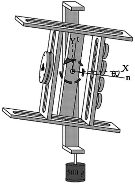
Experimental apparatus. The normal (n) and tangential (t) local axes are respectively coincident with the horizontal (X) and vertical (Y ) global axes when the handle orientation angle (θ) is zero. Axis Z completes the global system according to the right-hand rule. The sense of θ is defined by the right-hand rule in the slightly supinated posture shown, θ < 0. The depicted transducer configuration corresponds to task IMRL (Table 1)
Five multicomponent force/torque transducers were mounted on the handle and used to register finger forces (ATI Industrial Automation, Garner, NC, U.S.A.: 1 × Mini-40 transducer for the thumb and 4 × Nano-17 transducers for the fingers). The thumb transducer was positioned such that its normal axis intersected the axis of rotation at a position t = 0 along the tangential axis of the handle. The finger transducers were positioned symmetrically about t = 0 according to Table 1 (Sect. 2.3). The grasp width, or, equivalently, the distance along n between the transducer faces, was 8 cm. The transducer signals were amplified and multiplexed using a custom-constructed conditioning box (ATI Industrial Automation) before being routed to a 12-bit analog-digital converter (PCI-6031, National Instruments, Austin, TX, U.S.A.). The signals were sampled at a frequency of 50 Hz using software based on the LabView package (National Instruments, Austin, TX, U.S.A.). Based on the manufacturer’s specifications, errors of approximately 0.04 N were expected for the measured forces.
Table 1.
Experimental conditions
| Experimental condition |
Levels | Transducer locations (cm) |
|---|---|---|
| LOAD | 250, 500, 750 g | |
| ORIENTATION | −90° through +90° (15° increments) |
|
| TASK | I | I = 0 |
| IMn | I = 1, M = −1 | |
| IMw | I = 3, M = −3 | |
| IMRL | I = 3, M = 1, | |
| R = −1, L = −3 |
LOAD refers to the amount of weight added to the handle, and ORIENTATION is the angle θ in the n-t plane. TASK, I , M, R, and L refer to the index, middle, ring, and little fingers, respectively. “IMn” and “IMw” are two-finger tasks with “narrow” and “wide” finger spreading, respectively. The transducer locations represent the position on the t axis of the center of each transducer with respect to the T transducer center
The mass of the handle with transducers and without an attached load was 580 g. Loads of 250, 500, or 750 g were suspended from the bottom of the handle’s backing structure in a Z = 0 position (i.e., with the same Z coordinate as the center of each transducer) such that no moment was generated in the Y-Z plane. The loads were suspended via a rigid aluminum rod such that load oscillation was eliminated. To provide increased contact friction between the fingers and transducers, 100-grit sandpaper (Carborundum Abrasives, North America) was attached to the surface of each transducer. The coefficient of static friction (μ) between the fingers and the sandpaper was approximately 1.4 (previously measured; F. Gao, unpublished Master’s thesis, The Pennsylvania State University).
2.3 Procedure
After giving informed consent, all subjects were asked to wash their hands to reduce intersubject friction variability. The subjects then sat with an erect posture in a nonrotating chair that did not have armrests; their upper limbs were not supported. Subjects were required to grasp the handle with the thumb (T) and with either one (index – I), two (I and middle – M), or four (I, M, ring – R, and little – L) fingers (Table 1). They then began a series of 312 trials, each of which lasted 5 s. The 312 trials included 24 blocks of 13 handle ORIENTATIONS. One of three LOADS and one of four TASKS (finger combinations, see Table 1) were randomly assigned to each block. The 13 ORIENTATIONS were randomly presented in each block. Two repetitions of each of the 12 unique blocks were performed in a randomized order. Table 1 summarizes the experimental conditions, including the finger transducer locations for each task.
Data were continuously collected for each block of 13 ORIENTATIONS. To achieve the prescribed angle θ, subjects were required to match the current θ to a target θ that was displayed in real time on a computer monitor via the potentiometer output voltage. The beginning and end of each 5-s trial was determined automatically – when the subject oriented the handle to within a 2° window of the target θ, the trial began. If the difference between the actual θ and the target θ exceeded 2° at any point during the next 5 s, the trial was restarted. Subjects completed this task with ease for all ORIENTATIONS, LOADS, and TASKS; the trials were rarely restarted after the initial attainment of the target θ. This automatic trial determination allowed subjects to rest between trials for as long as they desired. Most subjects needed to rest at least once within a block of trials for the largest LOAD, but rest was almost never required for the two lighter LOADS. Each block of 13 ORIENTATIONS lasted an average of approximately 3 min. At the conclusion of the block, the data were logged and the combination of LOAD and TASK was changed.
While the handle orientation (θ) was prescribed in the n-t plane, and the level on the handle’s backing structure ensured no rotation in the Y-Z plane, neither the handle orientation in the X-Z plane nor the X-Y-Z location of the handle was prescribed. That is, subjects could manipulate the handle however they wished provided that they matched the target θ and that the handle did not rotate in the Y-Z plane. The decision for not prescribing all angles and positions was made on the basis of pilot studies. When the upper limb was supported on a table during pilot studies, subjects expressed substantial wrist discomfort while attempting to adopt the extreme ±90° postures without rotation in the X-Z plane. Since the wrist was apparently stressed in a manner not considered central to the task, the upper arm support was removed. Pilot subjects then performed the task while attempting to maintain a constant X-Y-Z handle position, but this proved to be exhaustive to upper-limb muscles that did not contribute directly to finger forces (e.g., deltoid, biceps, etc.). To avoid this similarly non-task-related stress, it was decided to allow any X-Z orientation and X-Y-Z position. The only constraints invoked were: (1) null Y-Z rotation and (2) subjects were permitted to neither rest their arm on their leg nor prop their arm on their torso.
2.4 Data processing and statistics
Data processing was performed using Matlab (The Math-Works Inc., Natick, MA, U.S.A.) and statistics were calculated using both Matlab and Minitab (Minitab Inc., State College, PA, U.S.A.). All statistical analyses were performed at a significance level α = 0.05.
The experimental data were analyzed at two levels: at the level of the thumb (T) and “virtual finger” (VF) and at the level of individual fingers. The concept of the VF was been introduced previously (Arbib et al. 1985; Iberall 1986) – the VF is an imagined finger that produces a wrench equal to the sum of the wrenches produced by all the fingers. The point of application of FVF depends on the distribution of finger forces. At the level of the thumb and VF, two analyses were conducted: (1) force patterns and (2) internal force. At the individual finger level, three further analyses were conducted: (3) force sharing, (4) safety margin, and (5) tissue deformation. ANOVA was applied to all analyses with SUBJECT, TASK, LOAD, and ORIENTATION as factors.
2.4.1 Level one: thumb and virtual finger
2.4.1.1. Force patterns
The force patterns in n-t and X-Y coordinate systems were documented and ANOVA was applied. ANOVA was rerun with DIRECTION as a factor where there were apparent differences between pronation and supination postures (see Sect. 3.1.1, for example). DIRECTION was not included initially because direction cannot be defined for θ = 0.
2.4.1.2. Internal force [(Fn)INT]
The internal force was defined for θ ≠ 0 as the total antagonistic (ANT) normal force; the ANT was (Fn)T for supination postures and (Fn)VF for pronation postures. Perhaps a more intuitive description of (Fn)INT is that it represents the agonist (AG) normal force in excess of that required to maintain equilibrium (i.e., in excess of Wsin θ). For θ = 0, (Fn)INT was defined as the grasping force or, equivalently, (Fn)VF or (Fn)T. This special definition for θ = 0 was employed to serve as a comparative “baseline” internal force.
2.5 Level two: individual fingers
2.4.2.1. Force sharing
The Fn sharing of an individual digit i was defined as (Fn)i/(Fn)VF, while the Ft sharing was defined as (Ft)i/Wcosθ. Ft sharing was undefined for θ = ±90°. It is conceptually distinct from Fn sharing because the thumb’s contribution is included and because it is defined in terms of external force. Ft sharing was defined in terms of Wcos θ, rather than (Ft)VF, because (Ft)VF can be zero at some handle orientations. Although the normal and tangential force sharing as defined herein are different mechanically, they both incorporate a denominator with a constant mechanical attribute. Sharing for the I task was not reported because Fn sharing was trivially 1.0 and Ft sharing could be inferred from the analysis at the “T and VF” level.
2.4.2.2. Safety margin
The safety margin (SM) has been defined in the literature (e.g., Burstedt et al. 1999) for individual digits as:
| (1) |
where i is an arbitrary digit. Equation 1 implies that the maximum value of the SM is 1 when a finger exerts no tangential force and that the minimum value of the SM is 0 if the normal force is just sufficient to prevent slip. The SM can be interpreted as the proportion of the exerted normal force that is not functioning for slip prevention. For simplicity it was assumed that μi was 1.4 for all digits, despite documentation of finger-dependent frictional characteristics (Kinoshita et al. 1997).
2.4.2.3. Tissue deformation (δt)
Tissue deformation in the tangential direction (δt) was calculated on the basis of previously measured (Pataky et al. 2004) lumped stiffness values (kt) for each finger that depended on the applied normal force:
| (2) |
Refer to Table 2 for the kt(Fn) function parameters and for clarification of (2). Normal tissue deformation was not calculated. The δt was measured because of its potential effect on Ft sharing (described in the accompanying paper). In the absence of slip, δt can be interpreted as displacement of the finger bone with respect to the grasped object.
Table 2.
Finger pad stiffness (kt) regressions on normal force (Fn) for tangential tissue displacement (δt) calculations (Pataky et al. 2004)
| Finger | m | b |
|---|---|---|
| I | 0.160 | 0.213 |
| M | 0.101 | 0.235 |
| R | 0.107 | 0.166 |
| L | 0.119 | 0.193 |
The slopes (m) have units: mm−1 and the Y -intercepts (b) have units: N mm−1. For example, for Fn = 1 N, the kt for the I finger was 0.373 N mm−1
3 Results
3.1 Level one: thumb and virtual finger
3.1.1 Force patterns
The T and VF forces changed in a systematic manner with the handle orientation angle θ. Figure 2 illustrates the average T and VF forces (pooled across SUBJECTS, LOADS, and TASKS) in all four coordinates: normal (n), tangential (t), global horizontal (X), and global vertical (Y). The data reveal behaviors that are either not mechanically necessitated or not immediately intuitive. For example, (Fn)T was nonzero for the −90° (supination) posture, and, similarly, (Fn)VF was nonzero for the +90° pronation posture; both “nonzero” results were confirmed for all LOAD levels by single-sided t-tests (p < 0.001). This was also seen in the Y coordinate plots: T and VF both exerted negative Y forces near full supination and full pronation, respectively (i.e., when the normal force acted downward). A second mechanically nonneces-sitated behavior was seen in pronation/supination differences in the X direction; ANOVA confirmed that both (FX)T and (FX)VF were indeed higher for pronation postures (p < 0.001).
Fig. 2.
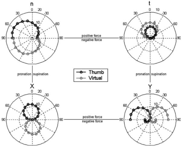
Thumb and virtual finger forces as a function of handle orientation angle in four coordinates: normal (n), tangential (t), horizontal (X), and vertical (Y ). All data points represent averages across SUBJECTS, TASKS, and LOADS. The left-hand and right-hand sides of each polar plot represent pronation and supination, respectively. The top half and bottom half of each plot represent positively directed and negatively directed force, respectively (positive senses are defined in Fig. 1). The T and VF forces corresponding to a given handle orientation are found along a single dotted diametric line. The outer concentric circle corresponds to 20 N for all coordinates except t (upper right); t has a radius of 10 N
3.1.2 Internal force
Figure 3 illustrates the (Fn)INT normalized by object weight (W) as a function of sin θ for all four tasks. The data were plotted against the sine of the orientation angle because sin θ represents the proportion of W that must be supported by the normal forces. Thus a line with constant slope on the (Fn)INT vs. sin θ plot would indicate that the (Fn)INT varies linearly with the required normal force. A straight horizontal line would indicate constant antagonist normal force.
Fig. 3.
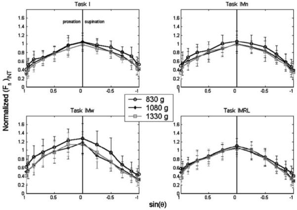
Internal normal force [(Fn)INT] as a function of the sine of the handle orientation angle θ. The internal force is normalized by object weight. Note that θ > 0 is shown on the left half of the plots; this convention was used for all figures and was selected for ease of interpretive transition between the polar and Cartesian plots
Figure 3 reveals that (Fn)INT varied parabolically with sin θ in an inverse-U-type fashion for all tasks. The (Fn)INT normalized with respect to W was substantial even when the handle was oriented horizontally: 0.43 ± 0.22 and 0.38 ± 0.18 for “full” pronation and supination, respectively. Despite the qualitatively similar results across tasks and LOADS seen in Fig. 3, ANOVA found significant effects of all the experimental factors: SUBJECT, TASK, LOAD, and ORIENTATION (Table 3) on the normalized (Fn)INT. Figure 3 reveals asymmetries in the (Fn)INT curve between pronation and supination postures; the (Fn)INT was generally lower when the hand was supinated. In summary, the (Fn)INT was not constant across θ, nor was it a simple trigonometric function of θ, and it was generally greater for pronated postures.
Table 3.
Probability values from the ANOVA tests
| Figure reference | Variable | Subject | Task | Load | Orientation |
|---|---|---|---|---|---|
| 3 (Internal force) | (Fn)INT/W | <0.001 | <0.001 | <0.001 | <0.001 |
| 4 (Fn sharing) | I | <0.001 | <0.001 | <0.001 | <0.001 |
| M | <0.001 | <0.001 | <0.001 | <0.001 | |
| R | <0.001 | × | 0.009 | <0.001 | |
| L | <0.001 | × | 0.018 | <0.001 | |
| 5 (Ft sharing) | I | <0.001 | <0.001 | 0.002 | <0.001 |
| M | <0.001 | <0.001 | 0.032 | <0.001 | |
| R | <0.001 | × | <0.001 | <0.001 | |
| L | <0.001 | × | 0.119 | <0.001 | |
| 6 (Safety margin) | (SM)T | <0.001 | <0.001 | <0.001 | <0.001 |
| (SM)I | <0.001 | <0.001 | 0.024 | <0.001 | |
| (SM)M | <0.001 | <0.001 | 0.295 | <0.001 | |
| (SM)R | <0.001 | × | <0.001 | <0.001 | |
| (SM)L | <0.001 | × | 0.024 | <0.001 | |
| 7 (Tissue deformation) | I | <0.001 | <0.001 | <0.001 | <0.001 |
| M | <0.001 | <0.001 | <0.001 | <0.001 | |
| R | <0.001 | × | <0.001 | <0.001 | |
| L | <0.001 | × | 0.811 | <0.001 |
The four factors for the ANOVAs were SUBJECT, TASK, LOAD, and ORIENTATION. The variables are listed in the second column; these variables correspond to those plotted in the figures listed in the first column. The factor–variable pairs that failed to reach significance at α = 0.05 are highlighted in bold
3.2 Level two: individual fingers
3.2.1 Force sharing
Recall that normal force sharing and tangential force sharing were defined differently (Sect. 2.4.2.1). Force sharing was not constant; it varied nonlinearly with θ (Figs. 4 and 5). The patterns of force sharing were unique for each TASK but appeared to be preserved for the different LOADS. To test this statistically, ANOVA was run separately for each finger’s sharing. Although the sharing percentages are not independent, the magnitude of each finger’s contribution may be considered in itself a function of θ. For example, ANOVA for each finger’s sharing percentage addresses questions like: “does the finger contribute a constant proportion of (Fn)total at different orientations?”
Fig. 4.
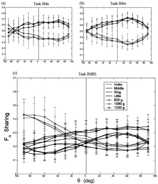
a–c. Normal force sharing among the fingers for the two-finger (a, b) and four-finger (c) tasks. Different fingers are represented by different shades and different LOADS are represented by different symbols. Error bars represent standard deviations. Note the different scales for the two-finger and four-finger tasks
Fig. 5.
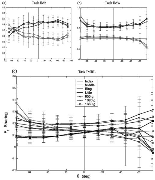
a–c. Tangential force sharing among the fingers for the two-finger (a, b) and four-finger (c) tasks. Symbols are as for Fig. 4. Note the different scales for the two-finger and four-finger tasks. Data are presented only to ±75° because Ft sharing is undefined for θ = ±90°. Also because of the definition of Ft sharing, the sum of the IMRL sharing is not necessarily equal to one, as is required for Fn sharing
Despite the apparent constancy across LOADS, ANOVA found significant effects of all four experimental factors on all force-sharing variables with the exception of the effect of LOAD on (Ft)L(p = 0.119) (Table 3). For the two-finger tasks, the middle finger produced a greater proportion of both (Fn)VF and (Ft)VF. This tendency was exaggerated for the IMw task, especially in the tangential force sharing. For the IMn task, the Ft sharing was practically constant in the range [−60, 40°], while the Fn sharing was not constant in this range. With increasing |θ| the I and M fingers’ normal sharing converged, but their tangential sharing contrastingly remained constant in the IMn task and diverged in the IMw task. For the IMRL task, F-tests for homogeneity of variance found significantly higher variability in Ft sharing for supination postures than for pronation postures for the “outer” I and L fingers, (p < 0.001), but not for the “inner” M or R fingers (p = 0.464 and 0.072, respectively).
3.2.2 Safety margin
Figure 6 illustrates the SM as a function of θ for the four different tasks. The SM varied with θ in a sinelike manner for all fingers. Despite the apparent similarities between tasks, ANOVA found significant effects of all experimental factors with the exception of LOAD on (SM)M (Table 3). For all digits, the variability in the SM was much smaller when the digit was a weight agonist (i.e., its Fn acted to support W) than when the digit was a weight antagonist. This was confirmed by F-tests for homogeneity of variance for all digits (T, I, R: p < 0.001; M: p = 0.031) except for L, which actually showed the opposite trend – its SM variability was smaller when it was a weight antagonist (p < 0.001). Figure 6 shows that when a digit was a weight agonist, the highest SM tended to occur at 75°, but when the digit was a weight antagonist, the highest SM tended to occur at 90°. For all digits, the minimum mean SM consistently occurred at between 15 and 45° when the digit was a weight antagonist.
Fig. 6.
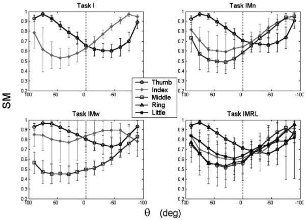
Safety margin (SM) as a function of handle orientation angle. The data represent averages across SUBJECTS and LOADS. A μ of 1.4 was assumed for all fingers
3.2.3 Fingertip tissue deformation
Tissue deformation in the tangential direction (δt) is presented in Fig. 7. There appeared to be little effect of LOAD on the amount of tissue deformation despite the dependence of the tissue stiffness on normal force. Despite these apparent trends, ANOVA found significant effects of all factors except for LOAD on (δt)L (Table 3). The δt results parallel the force results to some extent, but there are notable differences. For example, the (δt)i was fairly constant across θ for task IMw, while only (Ft)i sharing [not (Fn)i sharing] had any constancy with θ in task IMw.
Fig. 7.
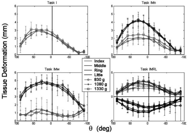
Tangential finger pad deformation (δt ) as a function of handle orientation. Different fingers are represented by different colors and different LOADS are represented by different symbols. Error bars represent standard deviations. For the IMRL task, the scale is different, and the supinator (R and L) fingers are illustrated on the opposite side of the δt = 0 line to avoid clutter
3.3 General arm kinematics
Despite the freedom in X-Z orientation and X-Y-Z position, subjects preferentially adopted handle locations and orientations that varied systematically with θ. This θ dependence was documented (although not quantified) with digital photographs for one subject and observed qualitatively for all subjects. It was found that subjects held the handle in a Y position of approximately neck height for 90° pronation and at approximately navel height for 90° supination postures. The Y position varied continuously between the two heights for the intermediate postures. A self-experiment may be conducted: one can feel the tension in the wrist extensors if one attempts to hold 90° supination at neck height and 90° pronation at navel height. The observed X and Z positions were approximately constant for all postures – at locations of the shoulder joint and forearm’s length, respectively. The X-Z orientation also varied systematically with θ: the n-t plane of the handle was perpendicular to the X-axis for 90° supination and perpendicular to the Z-axis for 90° pronation; it varied continuously for the intermediate postures. These systematic changes undoubtedly have a biomechanical basis and would be worth studying under more appropriately controlled experimental conditions.
4 Discussion
This study raises more questions than it answers. Some of the findings of the study match those described in earlier papers; other findings are novel and cannot be readily put into the context of existing hypotheses in the area of motor control in general and control of prehension in particular. Here we discuss relations of our findings to those published in earlier studies. The companion paper (Pataky et al. 2004) performs optimization-based analyses of the findings.
4.1 Mechanically unnecessary forces
The prehension literature details many task-dependent instances of mechanically unnecessary force production (e.g., Latash et al. 1998a,b; Cole et al. 1999; Zatsiorsky et al. 2000). Some of these effects were described as “enslaving” (Kilbreath and Gandieva 1994; Zatsiorsky et al. 2000; Schieber 2001) and were attributed to a feed-forward controller to physiologically connected effectors (Latash et al. 1998a,b). Considering the current data, enslaving can account for neither the large internal force nor the change in normal force sharing across orientations (Fig. 4). Nonvertical grasping requires a unique formulation of “unnecessary” forces because of the changing normal–tangential force requirements with object orientation; this is discussed further in the companion paper (Pataky et al. 2004).
4.2 Reproducibility of force-sharing patterns
For vertical grasping, Li (2002) reported normal force sharing among the IMRL digits to be: 31.4, 29.8, 23.9, and 14.9%, respectively, and tangential force sharing to be: 16.3, 31.8, 23.1, and 28.8%, respectively. The overall sharing patterns in our study are comparable. No published force sharing data are available for nonvertical postures.
Normal force-sharing reproducibility across loads is not a new finding. Many examples of this exist in the literature (e.g., Kinoshita et al. 1995; Latash et al. 1998a,b; Li et al. 1998; Radwin et al. 1992). Tangential force-sharing stability when load is changed is also not new (Pataky et al. 2004). The novelty of the present data is that this forcesharing constancy is maintained across loads at arbitrary object orientations.
4.3 Pronation/supination asymmetries
Despite the fact that the points of application of finger forces did not change from pronation to supination, we observed evident changes in the force characteristics. These included different force sharing and different SM profiles, among others. Pronation/supination asymmetries have been observed before. For example, human subjects produce different maximum voluntary hand grip torque between pronation and supination efforts (Adams and Peterson 1988; Timm et al. 1993). The asymmetries could be attributed, at least in part, to the dependence of the geometry of the finger flexor tendons on wrist posture (Keir and Wells 1999), which consequently affect externally observable finger forces (Werremeyer and Cole 1997). Muscle geometry changes, however, cannot explain the large changes in SM with orientation.
4.4 Task-specific variations in the safety margin
For the vertical orientation, the SM values were slightly higher than those previously reported earlier: Burstedt et al. (1999) reported values between 0.3 and 0.5 for the T, I, and M digits. The current data are on the order of 0.6–0.7 for vertical grasping (Fig. 6). The higher SM in the current study might be explained by the nature of the handle used in the present study; it was heavy with expensive force transducers attached but was freely held in space with no safety catch in the event of dropping. This is reminiscent of the “better safe than sorry” strategy documented for special populations (e.g., in elderly: Cole et al. 1999; Shim et al. 2004, and in cerebellar patients: Babin et al. 1999; Fellows et al. 2001).
The SM has been shown to change with frictional conditions (Burstedt et al. 1999). These changes, however, were small compared to the magnitude of the changes observed during the current study (which ranged from approximately 0.4 to greater than 0.9). The task mechanics described in Sect. 1 partially account for the large fluctuations but do not explain why the SM should change when normal forces do not act to support object weight.
4.5 Summary
The human central nervous system selects different finger force patterns when holding an object at various postures with respect to the gravity field. While it seems obvious that the forces should change, the manner in which these changes should occur between vertical and horizontal orientations is not obvious a priori. The current study documents these force patterns and demonstrates that no obvious mechanical parameter derivable from finger forces (including internal force, force sharing, and safety margin) is stabilized across orientations. Nonetheless, these measures change in a systematic manner with orientation, suggesting that the forces selected by the CNS are based on mechanical principles.
This is significant in the context of the literature because there is no measure presently available that can account for the mechanically necessitated interaction between normal and tangential finger forces. We suspect that a measure based on mathematically optimal solutions to the statically indeterminate problem of nonvertical grasping might explain the data. The analyses conducted in the companion paper (Pataky et al. 2004) reveal that optimization can account for many of the observed behaviors. This suggests that the CNS is likely to employ optimization procedures when controlling finger forces. The broader implication is that the CNS finds mechanically optimal solutions to problems involving mechanical redundancy.
Acknowledgements
Supported in part by NIH grants AR-48563, AG-018751 and NS-35032.
References
- Adams SK, Peterson PJ. Maximum voluntary hand grip torque for circular electrical connectors. Hum Factors. 1988;30(5):733–745. doi: 10.1177/001872088803000609. [DOI] [PubMed] [Google Scholar]
- Arbib MA, Iberall T, Lyons D. Coordinated control programs for movements of the hand. Exp Brain Res Suppl. 1985;10:111–129. [Google Scholar]
- Babin-Ratte S, Sirigu A, Gilles M, Wing A. Impaired anticipatory finger grip-force adjustments in a case of cerebellar degeneration. Exp Brain Res. 1999;128(1–2):81–85. doi: 10.1007/s002210050821. [DOI] [PubMed] [Google Scholar]
- Burstedt MK, Flanagan JR, Johansson RS. Control of grasp stability in humans under different frictional conditions during multidigit manipulation. J Neurophysiol. 1999;82(5):2393–2405. doi: 10.1152/jn.1999.82.5.2393. [DOI] [PubMed] [Google Scholar]
- Cole KJ, Rotella DL, Harper JG. Mechanisms for age-related changes of fingertip forces during precision gripping and lifting in adults. J Neurosci. 1999;19:3238–3247. doi: 10.1523/JNEUROSCI.19-08-03238.1999. [DOI] [PMC free article] [PubMed] [Google Scholar]
- Danion F, Schoner G, Latash ML, Li S, Scholz JP, Zatsiorsky VM. A mode hypothesis for finger interaction during multi-finger force-production tasks. Biol Cybern. 2003;88(2):91–98. doi: 10.1007/s00422-002-0336-z. [DOI] [PubMed] [Google Scholar]
- Fellows SJ, Ernst J, Schwarz M, Topper R, Noth J. Precision grip deficits in cerebellar disorders in man. Clin Neurophysiol. 2001;112(10):1793–1802. doi: 10.1016/s1388-2457(01)00623-x. [DOI] [PubMed] [Google Scholar]
- Iberall T. The representation of objects for grasping; Proceedings of the 8th Cognitive Society conference; 1986.pp. 547–561. [Google Scholar]
- Johansson RS, Backlin JL, Burstedt MK. Control of grasp stability during pronation and supination movements. Exp Brain Res. 1999;128(1):20–30. doi: 10.1007/s002210050813. [DOI] [PubMed] [Google Scholar]
- Keir PJ, Wells RP. Changes in geometry of the finger flexor tendons in the carpal tunnel with wrist posture and tendon load: an MRI study on normal wrists. Clin Biomech (Bristol, Avon) 1999;14(9):635–645. doi: 10.1016/s0268-0033(99)00012-1. [DOI] [PubMed] [Google Scholar]
- Kilbreath SL, Gandieva SC. Limited independent flexion of the thumb and fingers in human subjects. J Physiol. 1994;479:487–497. doi: 10.1113/jphysiol.1994.sp020312. [DOI] [PMC free article] [PubMed] [Google Scholar]
- Kinoshita H, Kawai S, Ikuta K. Contributions and co-ordination of individual fingers in multiple finger prehension. Ergonomics. 1995;38(6):1212–1230. doi: 10.1080/00140139508925183. [DOI] [PubMed] [Google Scholar]
- Kinoshita H, Backstrom L, Flanagan JR, Johansson RS. Tangential torque effects on the control of grip forces when holding objects with a precision grip. J Neurophysiol. 1997;78(3):1619–1630. doi: 10.1152/jn.1997.78.3.1619. [DOI] [PubMed] [Google Scholar]
- Latash ML, Gelfand IM, Li ZM, Zatsiorsky VM. Changes in the force-sharing pattern induced by modifications of visual feedback during force production by a set of fingers. Exp Brain Res. 1998a;123(3):255–262. doi: 10.1007/s002210050567. [DOI] [PubMed] [Google Scholar]
- Latash ML, Li ZM, Zatsiorsky VM. A principle of error compensation studied within a task of force production by a redundant set of fingers. Exp Brain Res. 1998b;122(2):131–138. doi: 10.1007/s002210050500. [DOI] [PubMed] [Google Scholar]
- Li ZM. Inter-digit co-ordination and object-digit interaction when holding an object with five digits. Ergonomics. 2002;45(6):425–440. doi: 10.1080/00140130210129673. [DOI] [PubMed] [Google Scholar]
- Li ZM, Latash ML, Zatsiorsky VM. Force sharing among fingers as a model of the redundancy problem. Exp Brain Res. 1998;119(3):276–286. doi: 10.1007/s002210050343. [DOI] [PubMed] [Google Scholar]
- Pataky TC, Latash ML, Zatsiorsky VM. Tangential load sharing among fingers during prehension. Ergonomics. 47(8):876–889. doi: 10.1080/00140130410001670381. [DOI] [PubMed] [Google Scholar]
- Pataky TC, Latash ML, Zatsiorsky VM. Prehension synergies during non-vertical grasping. II. Modeling and optimization. Biol Cybern. 2004 doi: 10.1007/s00422-004-0506-2. (in press). DOI 10.1007/s00422-004-0506-2. [DOI] [PMC free article] [PubMed] [Google Scholar]
- Pataky TC, Latash ML, Zatsiorsky VM. Viscoelastic response of the finger pad to incremental tangential displacements. J Biomech. 2004 doi: 10.1016/j.jbiomech.2004.07.004. in press. [DOI] [PubMed] [Google Scholar]
- Radwin RG, Oh S, Jensen TR, Webster JG. External finger forces in submaximal five-finger static pinch prehension. Ergonomics. 1992;35(3):275–288. doi: 10.1080/00140139208967813. [DOI] [PubMed] [Google Scholar]
- Schieber MH. Constraints on somatotopic organization in the primary motor cortex. J Neurophysiol. 2001;86:2125–2143. doi: 10.1152/jn.2001.86.5.2125. [DOI] [PubMed] [Google Scholar]
- Shim JK, Lay B, Zatsiorsky VM, Latash ML. Age-related changes in finger coordination in static prehension tasks. J Appl Physiol. 2004;97(1):213–24. doi: 10.1152/japplphysiol.00045.2004. Epub 5 March 2004. [DOI] [PMC free article] [PubMed] [Google Scholar]
- Timm WN, O’Driscoll SW, Johnson ME, An KN. Functional comparison of pronation and supination strengths. J Hand Ther. 1993;6(3):190–193. doi: 10.1016/s0894-1130(12)80131-1. [DOI] [PubMed] [Google Scholar]
- Werremeyer MM, Cole KJ. Wrist action affects precision grip force. J Neurophysiol. 1997;78(1):271–280. doi: 10.1152/jn.1997.78.1.271. [DOI] [PubMed] [Google Scholar]
- Westling G, Johansson RS. Factors influencing the force control during precision grip. Exp Brain Res. 1984;53(2):277–284. doi: 10.1007/BF00238156. [DOI] [PubMed] [Google Scholar]
- Zatsiorsky VM, Li ZM, Latash ML. Enslaving effects in multi-finger force production. Exp Brain Res. 2000;131(2):187–195. doi: 10.1007/s002219900261. [DOI] [PubMed] [Google Scholar]
- Zatsiorsky VM, Gregory RW, Latash ML. Force and torque production in static multifinger prehension: biomechanics and control: I. Biomechanics Biol Cybern. 2002a;87(1):50–57. doi: 10.1007/s00422-002-0321-6. [DOI] [PMC free article] [PubMed] [Google Scholar]
- Zatsiorsky VM, Gregory RW, Latash ML. Force and torque production in static multifinger prehension: biomechanics and control: II. Control. Biol Cybern. 2002b;87(1):40–49. doi: 10.1007/s00422-002-0320-7. [DOI] [PMC free article] [PubMed] [Google Scholar]