

Abstract
The goal of this study was to investigate the conjoint changes of digit forces/moments in 3 dimensions during static prehension under external torques acting on the object in one plane. The experimental paradigm was similar to holding a book vertically in the air where the center of mass of the book is located farther from the hand than the points of digit contacts. Three force and 3 moment components from each digit were recorded during static prehension of a customized handle. Subjects produced forces and moments in all 3 directions, although the external torques were exerted on the handheld object about only the Z-axis. The 3-dimensional response to a 2-dimensional task was explained by the cause– effect chain effects prompted by the noncollinearity of the normal forces of the thumb and the 4 fingers (represented by the “virtual finger”). Because the forces are not collinear (not along the same line), they generate moments of force about X- and Y-axes that are negated by the finger forces along the Y- and X-directions. The magnitudes of forces produced by lateral fingers (index and little) with longer moment arms were larger compared with the central fingers (middle and ring). At the virtual finger (an imaginary digit whose mechanical action is equivalent to the summed action of the 4 fingers) level, the relative contribution of different fractions of the resistive moment produced by subjects did not depend on the torque magnitude. We conclude that the CNS 1) solves a planar prehension task by producing forces and moments in all 3 directions, 2) uses mechanical advantage of fingers, and 3) shares the total torque among finger forces and moments in a particular way disregarding the torque magnitude.
INTRODUCTION
Many grasping tasks in everyday life require precise control of the handheld objects in 3 dimensions. However, the majority of previous studies on prehension were limited to planar tasks where the external torque on the object was either zero (Burstedt et al. 1997; Cole and Abbs 1988; Flanagan et al. 1999; Gordon et al. 1993; Johansson and Westling 1988) or exerted in the plane of the grasp (Rearick and Santello 2002; Santello and Soechting 2000; Shim et al. 2003; Zatsiorsky et al. 2003b), an imagined plane through which the points of force application of all the involved digits pass closely. In the latter tasks, either pronational or supinational effort against external torques was produced.
Analysis of findings in such “planar” studies has commonly been performed assuming a hierarchical scheme of the production of digit forces/moments. At the higher level of the hierarchy, forces/moments of the thumb and the virtual finger (VF) are defined. The VF is an imaginary finger that produces a wrench (the force and moment) equal to the sum of wrenches produced by all the fingers (Arbib et al. 1985; Cutkosky 1989; Cutkosky and Howe 1990; Gentilucci et al. 2003; Iberall 1987, 1997; MacKenzie and Iberall 1994; Omata 1991; Santello and Soechting 1997, 2000; Shim et al. 2003; Yoshikawa 1999; Zatsiorsky et al. 2004). At the lower level, the action of the VF is distributed among the individual fingers (IF).
It has been shown that forces and moments generated by the digits during multifinger prehension tasks change conjointly in a task-specific manner (i.e., they form a synergy(ies); for a review on prehension synergies see Zatsiorsky and Latash 2004). The coordinated changes of the finger forces and moments within a synergy are manifested by chain effects when a local change of an elemental variable (force, moment, or point of force application by a digit) leads to changes in other elemental variables (the term chain effect does not imply a temporal sequence but rather cause– effect adjustments that may take place conjointly (Shim et al. 2003; Zatsiorsky and Latash 2004; Zatsiorsky et al. 2004).
A number of studies have investigated 3-dimensional grasping by robotic hands (Omata 1991; Ponce and Faverjon 1995; Yamada et al. 2001; Yoshikawa 1996; Zhu et al. 2004). However, there have been only a limited number of studies addressing the human prehension in 3 dimensions. Tripod grasping involving the thumb and 2 other fingers to hold an object from above has been used to investigate the magnitudes and directions of the VF and IF forces with limited 3-dimensional analyses (Baud-Bovy and Soechting 2001; Burstedt et al. 1999; Gentilucci et al. 2003). In experiments of Kinoshita and colleagues (1997), the subjects pinched a flat object with the tips of the index finger and the thumb. The subjects resisted tangential force and torque with the aim of preventing the object from slipping. When the tangential force and tangential torque increased, the normal forces (the grasp force) also increased.
In the present study, we address a task in which an external torque acts in a plane perpendicular to the plane of the grasp (Fig. 1). Therefore the directions of external torque vectors applied to the handle in the present study were parallel to the Z-axis (they were parallel to the X-axis in our previous studies; Shim et al. 2003, 2004a,b; Zatsiorsky et al. 2002a, 2003b). In tasks studied in the present study, the external torques are mainly compensated by the subject’s efforts of radial or ulnar deviations. Such prehension tasks are fairly common in everyday life; they are similar to holding a book vertically in the air where the center of mass of the book is located farther from the hand than the points of digit contacts. The main goal of this study was to analyze the conjoint changes of digit forces/moments in 3 dimensions during static prehension under the action of external torques. We were mainly interested in the following questions:
How is the moment resisting external torque generated? Theoretically, there are several ways of producing the moment (they will be explained later in the text). What is the relative role of the various contributors into the total moment generated against the external torque acting on the object? Does their relative contribution depend on the torque magnitude and direction?
The task used in this study is essentially 2-dimensional in the sense that the external torque is exerted in the plane of the load action (thus the torque and load vectors are orthogonal), and the equilibrium could be achieved by generating resistive torque and force in that plane. Mechanically, there is no need for the digits to produce (and balance) forces and moments in other directions. For instance, it is not necessary to generate thumb or VF forces in the anterioposterior direction. Does the CNS solve the task as a planar task, or does it resort to solving it in 3 dimensions such that the forces along and moments around all the 3 directions are changed?
At the level of individual finger forces/moments, we hypothesize that the lateral fingers (the index and little) are the main contributors to the torque production. If this hypothesis is confirmed, it will indicate that during the prehension the fingers are activated according to their mechanical advantage (Buchanan et al. 1989; Devlin and Wastell 1986; Frey and Carlson 1994; Shim et al. 2004a; Smutz et al. 1998; Zatsiorsky et al. 2002a).
Based on the aforementioned hypotheses on a hierarchical control of prehension, we expect that a change of the external torque magnitude and direction will induce more systematic changes in variables at the VF level than at the IF level.
FIG. 1.

Experimental setup. Thumb and finger sensors (shown as white cylinders) were attached to vertical aluminum bars, and a movable load (shown as a black cylinder) was attached to the long horizontal aluminum beam. A transmitter (the small black cube) of a magnetic tracking device was attached to a Plexiglas base affixed to the top of the handle. , , , , and are the force vectors of the thumb, index, middle, ring, and little fingers and , , , , and are the force application point vectors of the thumb, index, middle, ring, and little fingers, respectively. MX, MY, and MZ are the global moments with respect to the global X-, Y-, and Z-axes; mx, my, and mz are the local moments with respect to the local x-, y-, and z-axes on each sensor, respectively; th, i, m, r, and l stand for the thumb, index, middle, ring, and little fingers.
METHODS
Subjects
Six right-handed males served as subjects (age: 26.2 ± 2.9 yr, weight: 71.7 ± 3.2 kg, height: 178.8 ± 4.1 cm, hand length: 19.1 ± 2.3 cm, hand width: 8.9 ± 1.1 cm). The hand length was measured between the middle fingertip and the distal crease of the wrist with the right hand extended. The subjects had no history of neuropathy or trauma to the upper limbs. All subjects gave informed consent according to the procedures approved by the Office for Research Protections of The Pennsylvania State University.
Equipment
Five 6-component (3 force and 3 moment components) transducers (4 Nano-17s for fingers and one Nano-25 for thumb; ATI Industrial Automation, Garner, NC) were attached to an aluminum handle to which an aluminum beam (3.8 × 52.1 × 0.6 cm) was affixed (Fig. 1). A 6-component (3 position and 3 angle components) magnetic tracking device (Polhemus FASTRAK, Rockwell Collins, Colchester, VT) was affixed to the top of the handle using a Plexiglas base (0.2 × 17.0 × 13.5 cm). The distance between the transmitter and the receiver was kept within 5 cm. The linearity of recordings about the X-, Y-, and Z-axes was tested using 11 angles with 1° intervals to ensure that the magnetic device was working properly with metallic objects around. The regression analysis on the actual versus recorded angles yielded the coefficients of determination (r2) of 0.98, 0.97, and 0.99 about the X-, Y-, and Z-axes, respectively.
The center of mass of the unloaded handle was determined by suspending the handle at different points. A load (0.32 kg) was attached to the beam with an eyehook that could be moved horizontally along a long slot of the beam. Sliding the weight along the beam produced different torques on the handle system about the Z-axis. The local x-, y-, and z-axes of each of the sensors were parallel to the global X-, Y-, and Z-axes, respectively.
The distance between the finger sensors in the Y-direction was 30 mm, and the thumb sensor was placed at a midpoint between the middle and ring fingers along the Y-axis. The grip width, which is the shortest distance between the contact surfaces of thumb and finger sensors in Z-direction, was 86 mm. Sandpaper (100-grit) was placed on the contact surface of each transducer to increase the friction between the digits and transducers. The finger pad–sandpaper static friction coefficient was about 1.4 –1.5 (previously measured; Zatsiorsky et al. 2002a). The sensors were aligned in the Y–Z plane.
Thirty analog signals from the sensors (5 sensors × 6 components) were routed to the 12-bit analog– digital converter (PCI-6031, National Instrument, Austin, TX). The signals from the magnetic device were sent to a serial port at the same time. All the signals were processed by a microcomputer (Dell Dimension 8330, Austin, TX).
A customized LabVIEW program was used for data acquisition, and MATLAB programs were written for data processing.
Experimental procedure
Subjects washed their hands with soap and warm water to normalize the skin condition. The subjects were given a familiarization session to the experimental devices and procedures to ensure that they were able to accomplish the experimental tasks.
The subjects sat on a chair and positioned their right upper arm on a wrist–forearm brace that was fixed to the table (Fig. 2). The forearm was held stationary with Velcro straps, and the wrist in the brace was locked in flexion– extension and ulnar deviations. The upper arm was abducted about 45° in the frontal plane and flexed 45° in the sagittal plane. The forearm was aligned parallel to a sagittal axis of the subject. When the subjects held the handle, the angle of the horizontal beam attached to the bottom of the handle was approximately at 135° with a frontal plane of the subject. The horizontal location of the center of mass of the handle without the load was measured. The top of the handle above the center of mass was connected to a rack (7.5 × 84.0 × 123.5 cm) using a cotton thread. The handle was suspended from the rack about 5 cm below a natural holding position of the hand. During the trials, the subjects grasped the handle and lifted it to a natural holding position. The subjects released the handle after each trial, and the handle was hanging from the rack between trials.
FIG. 2.
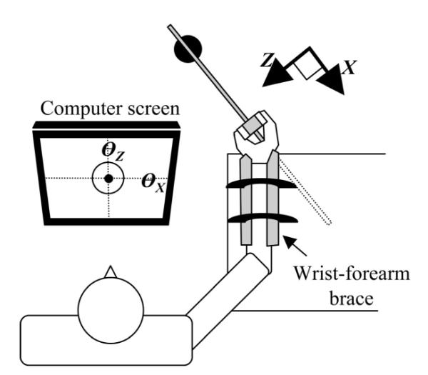
Subject position during experiment. Subject’s wrist and forearm were strapped with a brace. Subjects maintained the handle statically in the upright position by monitoring the handle orientation angles around the X- and Z-axes shown on the computer screen.
A load of 0.32 kg was suspended from the beam at 7 different positions that generated 7 different external torques about the Z-axis (−0.70, −0.47, −0.23, 0.00, 0.23, 0.47, and 0.70 Nm). The total weight of the handle, beam, transducers, and suspended load was 10.24 N. Hyperextended joint configurations were not allowed for any phalangeal joints of the hand during testing. The task and the instructions were designed in an attempt to achieve a stable trial-to-trial performance: The forearm, wrist, and hand positions were fixed, and the instructions given to the subjects were to grasp the handle in the same way by placing the fingertip centers at the centers of the sensors and to apply a minimal effort. Subjects were supposed to avoid rotating the handle system by watching a cursor on the computer screen showing the angular position of the handle about the X- and Z-axes. The horizontal and vertical axes on the screen corresponded to angular positions of the handle about the X- and Z-axes, respectively. A circle of 3.0 cm radius was shown at the center of the screen. The center of the circle represented 0° of the angular positions of the handle, and the radius of the circle represented 1°. The customized data collection software automatically stopped during experiments when the magnitude of angular displacement became greater than 1° () from a preselected handle position where the Y-axis was parallel to the direction of gravity.
In each trial, signals from all 30 channels were zeroed before subjects held the handle. When the subjects reported that they were holding the handle comfortably, data recording started. The subjects moved the cursor of the handle angular positions into the circle shown on the computer screen in 3 s. Twenty-five trials were performed for each external torque condition for the total of 175 trials for each subject. The subjects successfully performed the task. The number of trials where subjects failed to move the cursor in the circle or failed to keep the orientation of the handle within the 1° range was 3.6 ± 1.8 (mean ± SD across subjects) trials out of the total 175 trials.
The data were collected at the sampling frequency of 60 Hz for 6 s. A minimum 20-s rest interval was given to the subjects between trials, and a rest interval of 10 min was given between torque conditions to avoid fatigue effects. The order of torque conditions were pseudorandomized (balanced).
Data analysis
The recorded data were averaged over the second half of the 6-s period in each trial. The position of the points of digit force applications with respect to the center of the surface of the sensor was calculated as CoPx = −my/Fz and CoPy = −mx/Fz, where m is a moment recorded by a sensor and F is a digit force. Moments acting on the handle were calculated with respect to the thumb force application point on the X–Y plane whose Z-coordinate was located at the center of mass of the handle (Fig. 1).
Model
The individual digits make a soft-finger contact with the sensor (Arimoto et al. 2000; Mason and Salisbury 1985; Shim et al. 2003). In the soft-finger contacts, sticking a digit to the sensor is not allowed and the digits can only push but not pull on the sensors. Free moments at the contact around the local z-axes can be produced. The points of force application can displace in the local x–y plane because the digits can roll on the surface.
For the system to be at rest during prehension, the vector sum of all forces and the vector sum of all moments acting on the system, including external load and torque, should be equal to zero in all 3 directions ( and , where superscript T signifies vector transpose). Thus the following 6 equations (constraints) should be satisfied.
- The sum of the individual finger forces along the X-axis should be equal and opposite to the thumb force along the X-axis
(1) - The sum of the digit forces along the Y-axis should be equal and opposite to the weight (L) of the handheld object
(2) - The sum of the individual finger forces along the Z-axis should be equal and opposite to the thumb force along the Z-axis
(3) - The total moment produced by digit forces about the X-axis should be equal to zero
(4) - The total moment produced by digit forces about the Y-axis should be equal to zero
(5) - The total moment produced by digit forces and digit local free moments about the Z-axis should be equal and opposite to the external torque (Tq) applied to the system about the Z-axis
(6)
where j represents fingers [i.e., j = {i, m, r, l}]; k stands for all digits including the thumb [i.e., k = {th, i, m, r, l}]; subscripts X, Y, and Z stand for the direction of a force, a moment arm, or a moment; F stands for a force; d stands for a moment arm; and M and m represent a moment of force and a free moment, respectively; stands for a thumb local free moment produced on the surface of the sensor about z-axis (Fig. 3A; moment of twisting; Blau 1996; Zatsiorsky 2002); represents the VF local free moments (Fig. 3A; ); and represents a moment of the VF couple. When the individual tangential finger forces are directed in opposite directions they create a force couple and thus a rotational effect on the object. and are the moments produced by the and about the Z-axis (Fig. 3, C and D, respectively). Note that each of the finger force components can produce moments of force about 2 axes: about the axes Y and Z, about the axes Z and X, and about the axes X and Y.
FIG. 3.
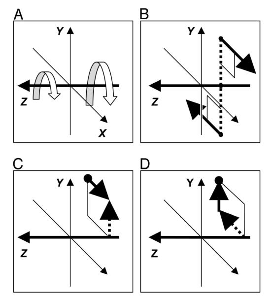
Sources of the total moment by digits about the Z-axis. A: thumb and virtual finger (VF) local free moments ( and ). B: moment of a VF couple acting in the X–Y plane [a free VF moment; ]. C: moment of. D: moment of . Line arrows are the forces and the dotted arrows are the moment arms.
VF forces and moments
The VF is an abstract representation of all 4 individual fingers. The VF acts as a functional unit to produce the same mechanical effects as all finger forces and moments combined (Arbib et al. 1985; Cutkosky 1989; Cutkosky and Howe 1990; Gentilucci et al. 2003; Iberall 1987, 1997; MacKenzie and Iberall 1994; Santello and Soechting 1997, 2000; Shim et al. 2003; Yoshikawa 1999; Zatsiorsky et al. 2004). The VF force is the vector sum of all 4 finger forces.
As any force, the VF force generates a moment of force about any axis that does not intersect its line of action. The VF produces also a free moment on the object. The VF free moment is attributed to (a) a VF force couple generated by the 4 fingers in the X–Y plane (e.g., the index and little fingers can generate opposite forces along the X-axis and Y-axis), which tend to rotate the handle, and (b) the VF local free moment , which is the sum of finger local free moments. Thus the total moment exerted by the VF on the objects is the sum of the moment of the VF force and the VF free moment; the latter is composed of (a) and (b)(Eq. 7)
| (7) |
where is the VF free moment, is a moment of the VF force couple, and is the VF local free moment (the horizontal lines above the symbols represent vectors). Because fingers do not stick to the sensors, they roll on the contact surface and do not produce local free moments about the X- and Y-axes. is thus generated only around the Z-axis by twisting friction of individual finger tips on contact surfaces ; the same is valid for the thumb local free moment, . The moment of the VF force couple is also exerted only about the Z-axis. This moment is exerted by the finger forces along the X- and Y-axes []: because the fingers do not stick, they cannot by themselves (i.e., without the thumb as a pivot) produce moments around the X- and Y-axes.
Sources of MZ
The total moment about the Z-axis (MZ) has 4 sources at the VF level explained in Fig. 3.
Statistics
Repeated-measures and mixed-effects ANOVA were used with the following factors: fingers (FINGER; 4 levels: index, middle, ring, and little fingers), force direction (FRC-DIR; 2 levels: normal and tangential forces), torque (TRQ; 7 levels: 7 external torque conditions of −0.70, −0.47, −0.23, 0.00, 0.23, 0.47, and 0.70 Nm). The factors were chosen based on particular comparisons. Coefficients of determination (r2) were computed with regression analyses between variables.
RESULTS
All subjects were able to maintain a stable handle position with a root-mean-square (RMS) error of under 0.14° with respect to all 3 axes, X, Y, and Z. Thus we have concluded that the subjects were able to perform the task successfully.
Moments resisting external torques
This section describes the contribution of free moments and moments of VF forces into the torque production about the Z-axis.
FREE MOMENTS: LOCAL FREE MOMENTS AND VF COUPLES
The local free moments of the thumb and VF about the Z-axis, respectively, and (the sum of individual local moments about the Z-axis; Fig. 3A), linearly scaled with the external torques (Fig. 4, A and B). The thumb local free moment about the Z-axis was larger than the VF local free moment in magnitude under the same external torque conditions (cf. the different scales in Fig. 4, A and B).
FIG. 4.

Moments exerted on the handle under different external torques. A: local moment of thumb (). B: VF local moment (). C: moment of a VF couple []. D: moments of VF FX []. Averaged data across trials and subjects are presented with SE bars (the error bars are too small to be seen for most data points). Note the different scales in the panels.
The moment of a VF couple about the Z-axis [; Fig. 3B] contributed the largest portion of the resistive moment (Fig. 4C). This moment was attributed to exerting individual tangential finger forces in opposite directions. The moment of the VF couple supported about 65% of the external torque, whereas the local free moments at the digit tips supported about 25%. The difference between the regression equations in the figures and the above percentages resulted from the exclusion of 0 Nm condition for the percentage calculation.
MOMENTS OF VF FORCES
The moment of the VF FX {; Fig. 3C] linearly scaled with the external torque and supported about 10% of the external torque (Fig. 4D). This moment is attributed to the difference between the X-components of the thumb and VF forces.
The vertical thumb and VF forces also generated a moment about the Z-axis. However, because of the small distance between the points of thumb and VF force application along the X-axis, the moment of VF FY [; Fig. 3D] was very small and supported only 0.4% of the external torque.
Note that the intercepts in all the regression equations in Fig. 4 are either zero or small. Thus the percentage contribution of the individual sources (i.e., the local free moments, the VF couple, the horizontal and vertical components of the VF force) into the total resistive moment does not depend on the torque magnitude.
Forces at VF level
The thumb and VF force components exerted along the X-, Y-, and Z-axes (, , , , , and ) changed symmetrically as a function of external torque, forming “X-shape” relations (Fig. 5). Note the very systematic and similar changes of the VF forces in all 3 directions. The sum of the forces in each panel in Fig. 5 was constant, as expected from the equilibrium Eqs. 1–3. The sum equaled zero in the X- and Z-directions, and it equaled the supported load in the Y-direction. The differences between the forces are proportional to the moments of force that these forces create (provided that the forces are not collinear). Note that these forces generate moments about all 3 axes and all the individual moments are compensated by other moments to keep the handle at equilibrium (see Fig. 6 as an example).
FIG. 5.

Relations among forces under different external torques in the VF level. A: thumb and VF forces along the X-axis ( and ). B: thumb and VF forces along the Y-axis ( and ). C: thumb and VF forces along the Z-axis ( and ). Averaged data across trials and subjects are presented with SE bars (the error bars are too small to be seen for most data points for forces along the Y- and Z-axes). Regression equations are provided for the thumb forces. Regression equations for the VF forces can be deduced from Eqs. 1–3 for force equilibrium. Note that the sum of the thumb and VF forces is constant across all the torques, whereas the difference in the forces is proportional to the moment of force that these forces generate.
FIG. 6.

Moments of force about the X-axis and their cancellation. A: moment of FZ couple about the X-axis []. B: moment of FY couple about the X-axis []. C: relation between [] and []. Note that [] cancels []. Averaged data across trials and subjects are presented with SE bars (some of the error bars are too small to be seen).
A repeated-measures ANOVA with the factor TRQ (7 level) was performed on each force variable at the VF level. The effect of TRQ was significant for all thumb and VF force components [F(6,30) >38, P < 0.001]. The pairs of external torque conditions with the same magnitude and different directions (i.e., 0.70 and −0.70, 0.47 and −0.47, and 0.23 and −0.23 Nm) were compared. All , , , and showed significant (P < 0.001) differences between the external torque conditions of the same magnitudes with the only exception of and under 0.23 and −0.23 Nm. However, at the torques of the same magnitude and were similar, disregarding of the torque direction.
Moments about X- and Y-axes
When the X- and Y-components of the thumb force and the same components of the VF force are of different magnitude, moments of force are exerted on the object. The moments are also exerted when the Z-components of the thumb and VF force are not collinear. The forces presented in Fig. 5 generate the moments of force not only about the Z-axis—which is overtly required by the task—but also about the X- and Y-axes. As an example, the moments created by different sources about the anterioposterior X-axis are presented in Fig. 6, A and B. These moments must be balanced to keep the object in equilibrium, as required by the task; thus there is a strong relation between the 3 moments (Fig. 6C).
Forces at IF level
The magnitude of IF force components along the X-axis (FX, Fig. 7A) increased systematically as a function of external torque; these components were zero under zero torque in all fingers. The magnitudes of the forces produced by lateral fingers (index and little) were greater than the magnitudes of the forces produced by the central fingers (middle and ring). Under the nonzero external torques, the forces produced by the radial fingers (index and middle) and the ulnar fingers (ring and little) were in opposite directions, with the exception of the middle finger force under negative external torques. The IF force components along the Z-axis (FZ, Fig. 7B) systematically increased with the increase in the external torque magnitude and formed “V-shape ” relations.
FIG. 7.

Relations among forces under different external torques in the individual finger (IF) level. A: IF forces along the X-axis. B: IF forces along the Y-axis. C: IF forces along the Z-axis. Averaged data across trials and subjects are presented with SE bars (the error bars are too small to be seen for most data points).
A series of 2-way mixed-effects ANOVAs and necessary pairwise comparisons were performed on the individual finger force components along the X-, Y-, and Z-axes with factors FINGER (4 levels: I, M, R, and L) and TRQ (7 levels: 7 external torque conditions). The effects of the factors and their interactions were all significant at P < 0.001 [(FX: FINGER: F(3,15) = 68, P < 0.001; TRQ: F(6,30) = 37, P < 0.001; FINGER × TRQ: F(18,90) = 1,061, P < 0.001; FY: FINGER: F(3,15) = 42, P < 0.001; TRQ: F(6,30) = 43, P < 0.001; FINGER × TRQ: F(18,90) = 43, P < 0.001; FZ: FINGER: F(3,15) = 2,027, P < 0.001; TRQ: F(6,30) = 176, P < 0.001; FINGER × TRQ: F(18,90) = 55, P < 0.001].
At large torques, the normal and tangential forces of the lateral fingers were larger than the normal and tangential forces of the central fingers, with the exception of the little finger normal forces (Fig. 7). This was confirmed by a 3-way mixed-effects ANOVA on the individual finger normal forces (FZ) and the tangential forces () with factors FINGER (4 levels: I, M, R, and L), FRC-DIR (2 levels: normal and tangential), and TRQ (7 levels: 7 external torque conditions). The effects of the factors and their interactions were all significant at P < 0.001 [FINGER: F(3,15) = 27, P < 0.001; FRC-DIR: F(1,5) = 75, P < 0.001; TRQ: F(6,30) = 163, P < 0.001; FINGER × FRC-DIR: F(3,15) = 96, P < 0.001; FINGER × TRQ: F(18,90) = 19, P < 0.001; FRC-DIR × TRQ: F(6,30) = 8, P < 0.001; FINGER × FRC-DIR × TRQ: F(18,90) = 26, P < 0.001].
The relations between the normal forces and the magnitude of the tangential forces resemble a distorted and rotated letter “V” (Fig. 8).
FIG. 8.

Individual finger normal (FZ) and tangential (∣ FXY∣) forces. A: lateral fingers: index (I) and little (L). B: central fingers: middle (M) and ring (R). Data points are connected in the order of external torques: 0.70, 0.47, 0.23, 0, −0.23, −0.47, and −0.70 Nm. Averaged data across trials and subjects are presented with SE bars (some of the error bars are too small to be seen). Absolute values of tangential forces are shown in the graph.
Relations between normal and tangential forces at IF and VF levels
The ratio of individual finger and VF normal force to the tangential force (FZ/∣ FXY ∣) under each external torque condition was calculated to examine whether the tangential and normal forces changed similarly with the external torque. The ratio is indicative of the resultant force direction. The force ratios at the IF level changed without a clear rule (Fig. 9A). However, the force ratio of the VF finger force changed in a systematic way (Fig. 9B); the ratio increased with the magnitude of external torque.
FIG. 9.

Ratio of the normal force (FZ) to tangential forces (∣ FXY ∣) for (A) the individual fingers and (B) the virtual finger. Averaged data across trials and subjects are presented with SE bars (some of the error bars are too small to be seen).
Two-way mixed-effects ANOVAs on the data from individual finger force ratios with the factor TRQ (7 levels: 7 external torque conditions) showed a significant effect of TRQ [F(6,30) >6, P < 0.001], and a similar ANOVA on VF force ratios with the same factor showed a highly significant effect of TRQ [F(6,30) >109, P < 0.001]. All individual fingers showed significant differences in the force ratio between the tasks with the external torques of the same magnitude and opposite direction (P < 0.05). The only exception was the middle finger force for the 0.23 and −0.23 Nm conditions. In contrast, VF finger force ratios were distributed symmetrically with respect to the torque direction; they did not show any differences for the opposite external torques of the same magnitude.
The differences between the patterns in Fig. 9, A and B, result from different dependencies of the normal and tangential forces of IF and VF on the external torque. These dependencies are illustrated in Fig. 9, C and D. Note that the patterns for the normal forces are similar for the VF and IFs. However, there are dramatic differences in the changes of IF tangential forces and VF tangential force with external torque (Fig. 9D). At large magnitudes of the external torque, tangential forces of all fingers show large magnitudes. However, because these forces exert forces in dissimilar directions, the VF tangential force actually becomes smaller in magnitude with an increase in the external torque.
DISCUSSION
The discussion addresses the following topics: 1) resistive moment sources against external torques, 2) “chain effects ” as mechanisms of generating resistive moments about the X- and Y-axes (these moments are not immediately required by the task mechanics), and 3) systematic changes of forces and force ratios at IF and VF levels.
Resistive moments
In planar tasks, a moment on the handheld object in the plane of the grasp is generated both by the normal and tangential finger forces (Shim et al. 2003, 2004a,b; Zatsiorsky et al. 2002a,b, 2003a,b). The contribution of the tangential forces into the total moment production depends on the width of the grasp and can exceed 50% of the total moment (Zatsiorsky et al. 2003b).
In contrast, in the grasping task studied in the present experiment, the moment of normal digit forces does not contribute to the resistive moment against an external torque because the direction of the moment is orthogonal to the direction of the external torque. Instead, the resistive moment arises from the 4 sources: the horizontal and vertical tangential VF forces (Fig. 3, C and D) and 2 components of the VF free moments: 1) the local moments (, arising at the individual digit tips; Fig. 3A) and 2) the moment of a VF force couple [, caused by exerting individual finger forces in opposite directions; Fig. 3B].
The percentage contribution of moment of tangential couple on average was 65% of the total resistive moment. The couple was generated by 2 sets of fingers located above and below the thumb pivot point (the index finger and the ring and little fingers, respectively) (Fig. 7). The middle finger always generated a small positive force in the X-direction and thus always contributed to the production of the positive (counterclockwise) moment about the Z-axis regardless of the external torque conditions.
The share of the local free moments (twist moments) in the present study was on average 25% of the total resistive moment. In human prehension, the revolute joints at the interphalangeal joints and universal joints at the metacarpophalageal joints do not allow for an active local moment production at the finger tips. Therefore it seems that the local free moments are attributed to the passive resistance of the deformable digit tip tissues.
For a circular contact area of radius R, the moment M of twisting friction force can be found by integrating the pressure p across the contact area A as in Eq. 8 (Blau 1996; Zatsiorsky 2002)
| (8) |
where μt is the twisting friction coefficient and r is the distance from the center of surface.
Theoretical studies of soft-finger contact have reported that the frictional limit attributed to the tangential force and the frictional limit resulting from the twisting moment are not dependent on each other, but they are linearly additive as in Eq. 9 (Howe et al. 1988; Omata 1991). Therefore the larger tangential force a finger generates the smaller twisting moment the finger resists
| (9) |
where F t is the tangential force, F n is the normal force, and μt is the static friction coefficient. The experimental results in human prehension by Kinoshita et al. (1997) showed a similar trend, although the authors reported that the tangential force and the twisting moment did not influence the normal force in a purely additive fashion. They have shown that an increase in the normal force for a given twisting moment increase is smaller for larger tangential forces. In this study, the local free moment of thumb was 50% greater than the sum of the local free moments of fingers (VF local free moment). It is plausible that the large tangential forces generated by the individual fingers to resist the external torques played a role in reducing their local free moments.
The strong linear relations with minimal intercepts between the external torque and the moments generated or resisted by the 4 sources (Fig. 4) indicate that the percentage sharing of the sources into the total resistive moment does not depend on the torque magnitude and is constant throughout the tasks.
Chain effects
An evident conclusion from the 3 panels of Fig. 5 is that people react to changes in the external torque about one axis (Z-axis) by exerting moments in all 3 dimensions. The goal of this section is to discuss possible mechanisms behind the coordinated and analogous changes of VF and thumb forces along all 3 coordinate axes. We see this explanation in the chain effects. The chain effects were previously suggested to explain the complex adjustments of the finger forces to task requirements in planar tasks (Zatsiorsky and Latash 2004; Zatsiorsky et al. 2003b). In the study of Zatsiorsky et al. (2003b), for example, the chain effects were used to explain how one relation between a pair of variables, such as a relation between and , imposes a relation between another pair of variables, such as between and . It seems that similar effects are also observed in 3 dimensions. The finger force scaling under external torques as shown in Fig. 5 can be explained with the following chain of events.
To sustain large external torques about the Z-axis, the CNS has to produce large tangential forces by the “lateral” fingers (Fig. 7A).
Large tangential forces require large normal forces to prevent the handle from slipping out off the hand (Fig. 7B).
The line of action of the VF normal force is not collinear with the line of action of the thumb normal force (this major experimental finding could not be predicted from the grasp mechanics). The VF and the thumb normal forces are equal and opposite (Fig. 5C). Thus they form a force couple that generates rotational effects about the X- and Y-axes.
To preserve the rotational equilibrium of the handle, the moments of the couple must be counterbalanced. It is achieved by moments generated by the X- and Y-force components (an example is given in Fig. 6). In particular, Fig. 7C illustrates a strong negative relation between the moments of force exerted by the Z- and Y-force components about the X-axis. Thus the systematic relations in Fig. 5, B and C are mechanically necessary.
In the described chain of events, all of the links of the chain but one are mechanically necessitated. The only event that is not defined by the task mechanics, but represents a choice made by the central controller, is the location of the point of application of the normal VF force with respect to the point of application of the thumb force. This location determines the magnitude and direction of the moments produced by the couple and, as a consequence, the magnitude and direction of the counterbalancing moments as well as the forces acting along the X- and Y-axes.
Solving a planar task in 3 dimensions requires exerting “additional ” forces that are not immediately required by the task mechanics. For instance, if the performers exerted the thumb and VF normal forces collinearly, such that the forces canceled each other and did not produce the moments of force about X- and Y-axes, the moments about these axes would be zero and the “additional forces” that compensate for these moments would not be required. However, the CNS prefers exerting the noncollinear thumb and VF normal forces that may look uneconomical. In a previous study (Zatsiorsky et al. 2002a), methods of mathematical optimization were applied to study the planar grasping tasks and some uneconomical patterns of finger activation—in particular the activation of antagonist fingers, that is, the fingers that generate a moment of force opposite to the required moment direction (Shim et al. 2004a,b; Zatsiorsky et al. 2002a)—have been explained by the finger interdependence (for a recent review on the finger interdependence see Schieber and Santello 2004), in particular by the enslaving effects (Li et al. 1998; Zatsiorsky et al. 2000). The antagonist fingers produce the force as a consequence of the strong activation commands to the fingers that generate a moment in the direction required by 2-dimensional grasping tasks. It remains to be investigated whether similar mechanisms may account for the observed production of the finger force in all 3 dimensions during the 2-dimensional tasks.
Finger forces at IF and VF levels
MECHANICAL ADVANTAGE OF FINGERS AT IF LEVEL
The index and little fingers had longer moment arms with respect to the thumb pivot point and also generated larger tangential forces than the central fingers (Fig. 7). Mechanical advantage of effectors, both muscles and fingers, has been suggested to explain different levels of effector activation observed in various motor tasks (Buchanan et al. 1989, 1993; Kuo 1994; Prilutsky 2000; Shim et al. 2004a; Zatsiorsky et al. 2002a). The hypothesis is simple: the effectors are activated in proportion to their mechanical advantage for the task. With regard to the finger forces, some experimental evidence corroborates the hypothesis. Zatsiorsky and colleagues (2002a) reported a nonlinear dependencies of IF normal forces on the mechanical advantage of the individual fingers during the torque production on the handheld objects maintained in the air. However, a study of finger coordination during torque production on a mechanically fixed object with different locations of the axis of rotation (Shim et al. 2004a) partially confirmed the hypothesis. As expected, the contribution to the total moment by the resultant force and the moment of normal forces increased with the moment arm increase. However, contrary to the expectations, the apparent stiffness (finger force divided by its moment arm) varied substantially with changes in the handle location and across the fingers.
The data from the present study corroborate the mechanical advantage hypothesis for the finger tangential forces in the sense that the fingers with larger mechanical advantage generate or resist larger forces. It is not known, however, whether this observation is the result of active neural control or passive properties of the hand as a mechanical structure. The larger activation of fingers with larger mechanical advantage can be considered an optimal solution to minimize the total effort (Buchanan et al. 1989; Shim et al. 2004a; Zatsiorsky et al. 2002a). However, mechanics at fingertips can also explain the larger forces of the “lateral” fingers. During grasping by immobile effectors aligned in parallel, as in this experiment, a small angular deviation of the handle induces a tangential deformation of the fingertips. If a fingertip resists the deformation, the tangential force (F) of the finger will depend on the angular deviation (θ) and the moment arm (r) from the axis of rotation; F = k′θr = kr, where k is the coefficient of apparent stiffness. Because the “lateral” fingers had larger r in this study, larger tangential forces could be expected even without an active involvement of the CNS. Presently, the relation between the passive mechanical properties of the hand and the active finger control is not well understood.
HIERARCHICAL CONTROL AND PREHENSION SYNERGIES
The ratio between the normal and tangential forces represents the tangent of a projection angle of the force vector on the tangential plane. When the ratio stays constant, the force direction with respect to the plane (a projection angle) does not change. Changes of the ratios at the VF level were more systematic and much larger than at the IF level. At the VF level, a symmetric parabolic pattern with respect to the external torque was observed corresponding to a change in the direction of the VF force from about 45 to over 80° (Fig. 9B), whereas the patterns for individual fingers were different and varied (Fig. 9A). The ring finger showed relatively minor changes in the force direction, which stayed about 45° for all external torques; the index and little fingers showed modest changes (by about 20°) in the direction of their forces with a change in the direction of the external torque but not with its magnitude. Only the middle finger showed significant changes in its force direction for negative values of the external torque. The bottom 2 panels of Fig. 9 shed some light on the nature of these differences. There are qualitative similarities in the behavior of FZ with external torque for individual fingers and for the VF. However, the magnitude of the tangential force shows strikingly different patterns with increasing external torque, an increase for individual fingers, and a decrease for the VF. Apparently, increasing ∣ FXY ∣ of IFs is associated with changes in the directions of the tangential finger forces in the X–Y plane such that ∣ FXY ∣ of the VF decreases.
These observations provide support for the idea on hierarchical control by the CNS of the normal and tangential digit forces: A systematic pattern at the VF level is achieved as a result of the summation of IF forces whose patterns of change are more variable compared with the pattern of the resultant force. In other words, a stable performance at the VF level is achieved using a synergy among elemental variables at the IF level (Zatsiorsky and Latash 2004). This synergy may partly be defined by mechanical constraints that lead to obligatory covariation of the tangential forces produced by individual fingers, similar to the example described in Chain effects.
Currently, we cannot discuss specific neurophysiological mechanisms that would map on the suggested hierarchical scheme of control. Indirect support for such a scheme comes from data on limited individuation of finger forces and on the organization of the neural input to finger muscles (Fuglevand et al. 1999; Li et al. 1998; Ohtsuki 1981; Schieber and Santello 2004; Zatsiorsky et al. 2000). These studies make a strong point that individual finger forces are not manipulated independently by the CNS.
The existence of IF synergies that stabilize the motor output at the VF level justifies the notion of VF (Arbib et al. 1985; Iberall 1987). It also provides indirect support for an idea that control of natural motor actions is based on hierarchies of synergies that at each level stabilize variables at the next hierarchically higher level (Latash et al. 2003).
In the current study, we have addressed changes in digit forces and moments with changes in the external torque. The issue of trial-to-trial variability when the external torque was kept constant has not been considered, although this issue is of a major importance for motor control as we addressed in an earlier studies with 2-dimensional analysis of prehension (Shim et al. 2003, 2004b). We plan to perform a trial-to-trial analysis on changes in digit forces/moments in 3 dimensions and present these data as a sequel to the analysis and discussion of the current study.
Acknowledgments
GRANTS This study was supported in part by National Institutes of Health Grants AG-018751, AR-048563, M01 RR-10732, and NS-35032.
REFERENCES
- Arbib MA, Iberall T, Lyons D. Coordinated control programs for movements of the hand. In: Goodwin AW, Darian-Smith I, editors. Hand Function and the Neocortex (Experimental Brain Research Supplement) vol. 10. Springer-Verlag; Berlin: 1985. [Google Scholar]
- Arimoto S, Nguyen PTA, Han HY, Doulgeri Z. Dynamics and control of a set of dual fingers with soft tips. Robotica. 2000;18:71–80. [Google Scholar]
- Baud-Bovy G, Soechting JF. Two virtual fingers in the control of the tripod grasp. J Neurophysiol. 2001;86:604–615. doi: 10.1152/jn.2001.86.2.604. [DOI] [PubMed] [Google Scholar]
- Blau PJ. Friction Science and Technology. Marcel Dekker; New York: 1996. [Google Scholar]
- Buchanan TS, Moniz MJ, Dewald JP, Zev Rymer W. Estimation of muscle forces about the wrist joint during isometric tasks using an EMG coefficient method. J Biomech. 1993;26:547–560. doi: 10.1016/0021-9290(93)90016-8. [DOI] [PubMed] [Google Scholar]
- Buchanan TS, Rovai GP, Rymer WZ. Strategies for muscle activation during isometric torque generation at the human elbow. J Neurophysiol. 1989;62:1201–1212. doi: 10.1152/jn.1989.62.6.1201. [DOI] [PubMed] [Google Scholar]
- Burstedt MK, Birznieks I, Edin BB, Johansson RS. Control of forces applied by individual fingers engaged in restraint of an active object. J Neurophysiol. 1997;78:117–128. doi: 10.1152/jn.1997.78.1.117. [DOI] [PubMed] [Google Scholar]
- Burstedt MK, Flanagan JR, Johansson RS. Control of grasp stability in humans under different frictional conditions during multidigit manipulation. J Neurophysiol. 1999;82:2393–2405. doi: 10.1152/jn.1999.82.5.2393. [DOI] [PubMed] [Google Scholar]
- Cole KJ, Abbs JH. Grip force adjustments evoked by load force perturbations of a grasped object. J Neurophysiol. 1988;60:1513–1522. doi: 10.1152/jn.1988.60.4.1513. [DOI] [PubMed] [Google Scholar]
- Cutkosky MR. On grasp choice, grasp models and the design of hands for manufacturing tasks. IEEE Trans Robotics Automation. 1989;5:269–279. [Google Scholar]
- Cutkosky MR, Howe RD. Dextrous Robot Hands. Springer-Verlag; New York: 1990. [Google Scholar]
- Devlin H, Wastell DG. The mechanical advantage of biting with the posterior teeth. J Oral Rehabil. 1986;13:607–610. doi: 10.1111/j.1365-2842.1986.tb00684.x. [DOI] [PubMed] [Google Scholar]
- Flanagan JR, Burstedt MK, Johansson RS. Control of fingertip forces in multidigit manipulation. J Neurophysiol. 1999;81:1706–1717. doi: 10.1152/jn.1999.81.4.1706. [DOI] [PubMed] [Google Scholar]
- Frey DD, Carlson LE. A body powered prehensor with variable mechanical advantage. Prosthet Orthot Int. 1994;18:118–123. doi: 10.3109/03093649409164394. [DOI] [PubMed] [Google Scholar]
- Fuglevand AJ, Macefield VG, Bigland-Ritchie B. Force-frequency and fatigue properties of motor units in muscles that control digits of the human hand. J Neurophysiol. 1999;81:1718–1729. doi: 10.1152/jn.1999.81.4.1718. [DOI] [PubMed] [Google Scholar]
- Gentilucci M, Caselli L, Secchi C. Finger control in the tripod grasp. Exp Brain Res. 2003;149:351–360. doi: 10.1007/s00221-002-1359-3. [DOI] [PubMed] [Google Scholar]
- Gordon AM, Westling G, Cole KJ, Johansson RS. Memory representations underlying motor commands used during manipulation of common and novel objects. J Neurophysiol. 1993;69:1789–1796. doi: 10.1152/jn.1993.69.6.1789. [DOI] [PubMed] [Google Scholar]
- Howe RD, Kao I, Cutkosky MR. The sliding of robot fingers under combined torsion and shear loading. Proc IEEE Int Conf on Robotics and Automation; Philadelphia, PA. 1988.pp. 24–29. [Google Scholar]
- Iberall T. The nature of human prehension: three dexterous hands in one. Proc IEEE Int Conf on Robotics and Automation; Raleigh, NC. 1987. [Google Scholar]
- Iberall T. Human prehension and dexterous robot hands. Int J Robotics Res. 1997;16:285–299. [Google Scholar]
- Johansson RS, Westling G. Coordinated isometric muscle commands adequately and erroneously programmed for the weight during lifting task with precision grip. Exp Brain Res. 1988;71:59–71. doi: 10.1007/BF00247522. [DOI] [PubMed] [Google Scholar]
- Kinoshita H, Backstrom L, Flanagan JR, Johansson RS. Tangential torque effects on the control of grip forces when holding objects with a precision grip. J Neurophysiol. 1997;78:1619–1630. doi: 10.1152/jn.1997.78.3.1619. [DOI] [PubMed] [Google Scholar]
- Kuo AD. A mechanical analysis of force distribution between redundant multiple degree-of-freedom actuators in human: implications for the central nervous system. Hum Mov Sci. 1994;12:635–663. [Google Scholar]
- Latash ML, Danion F, Scholz JF, Schoner G. Coordination of multielement motor systems based on motor abundance. In: Latash ML, Levin MF, editors. Progress in Motor Control: Effects of Age, Disorder, and Rehabilitation. vol. 3. Human Kinetics; Urbana, IL: 2003. pp. 97–124. [Google Scholar]
- Li ZM, Latash ML, Zatsiorsky VM. Force sharing among fingers as a model of the redundancy problem. Exp Brain Res. 1998;119:276–286. doi: 10.1007/s002210050343. [DOI] [PubMed] [Google Scholar]
- MacKenzie CL, Iberall T. The Grasping Hand. Elsevier Science; Amsterdam: 1994. [Google Scholar]
- Mason MT, Salisbury KJ. Robot Hands and the Mechanics of Manipulation (Artificial Intelligence) MIT Press; Cambridge, MA: 1985. [Google Scholar]
- Ohtsuki T. Inhibition of individual fingers during grip strength exertion. Ergonomics. 1981;24:21–36. doi: 10.1080/00140138108924827. [DOI] [PubMed] [Google Scholar]
- Omata T. An algorithm for computing fingertip positions of a spatial equilibrium grasp with a multifingered hand. Proc IEEE/RSJ Int Workshop on Intelligent Robots and Systems IROS ’91; Osaka, Japan. 1991.pp. 711–716. [Google Scholar]
- Ponce J, Faverjon B. On computing three-finger force-closure grasps of polygonal objects. IEEE Trans Robotics Automation. 1995;11:868–881. [Google Scholar]
- Prilutsky BI. Coordination of two- and one-joint muscles: functional consequences and implications for motor control. Motor Control. 2000;4:1–44. doi: 10.1123/mcj.4.1.1. [DOI] [PubMed] [Google Scholar]
- Rearick MP, Santello M. Force synergies for multifingered grasping: effect of predictability in object center of mass and handedness. Exp Brain Res. 2002;144:38–49. doi: 10.1007/s00221-002-1024-x. [DOI] [PubMed] [Google Scholar]
- Santello M, Soechting JF. Matching object size by controlling finger span and hand shape. Somatosens Mot Res. 1997;14:203–212. doi: 10.1080/08990229771060. [DOI] [PubMed] [Google Scholar]
- Santello M, Soechting JF. Force synergies for multifingered grasping. Exp Brain Res. 2000;133:457–467. doi: 10.1007/s002210000420. [DOI] [PubMed] [Google Scholar]
- Schieber MH, Santello M. Hand function: peripheral and central constraints on performance. J Appl Physiol. 2004;96:2293–2300. doi: 10.1152/japplphysiol.01063.2003. [DOI] [PubMed] [Google Scholar]
- Shim JK, Latash ML, Zatsiorsky VM. Prehension synergies: trial-to-trial variability and hierarchical organization of stable performance. Exp Brain Res. 2003;152:173–184. doi: 10.1007/s00221-003-1527-0. [DOI] [PMC free article] [PubMed] [Google Scholar]
- Shim JK, Latash ML, Zatsiorsky VM. Finger coordination during moment production on a mechanically fixed object. Exp Brain Res. 2004a;157:457–467. doi: 10.1007/s00221-004-1859-4. [DOI] [PMC free article] [PubMed] [Google Scholar]
- Shim JK, Lay BS, Zatsiorsky VM, Latash ML. Age-related changes in finger coordination in static prehension tasks. J Appl Physiol. 2004b;97:213–224. doi: 10.1152/japplphysiol.00045.2004. [DOI] [PMC free article] [PubMed] [Google Scholar]
- Smutz WP, Kongsayreepong A, Hughes RE, Niebur G, Cooney WP, An KN. Mechanical advantage of the thumb muscles. J Biomech. 1998;31:565–570. doi: 10.1016/s0021-9290(98)00043-8. [DOI] [PubMed] [Google Scholar]
- Yamada T, Koishikura T, Mizuno Y, Mimura N, Funahashi Y. Stability analysis of 3D grasps by a multifingered hand. Proc IEEE Int Conf on Robotics and Automation; Seoul, Korea. 2001. [Google Scholar]
- Yoshikawa T. Passive and active closures by constraining mechanisms. Proc Int Conf on Robotics and Automation; Minneapolis, MN. 1996.pp. 1477–1484. [Google Scholar]
- Yoshikawa T. Virtual truss model for characterization of internal forces for multiple finger grasps. IEEE Trans Robotics Automation. 1999;15:941–947. [Google Scholar]
- Zatsiorsky VM. Kinetics of Human Motion. Human Kinetics; Champaign, IL: 2002. [Google Scholar]
- Zatsiorsky VM, Gao F, Latash ML. Finger force vectors in multi-finger prehension. J Biomech. 2003a;36:1745–1749. doi: 10.1016/s0021-9290(03)00062-9. [DOI] [PMC free article] [PubMed] [Google Scholar]
- Zatsiorsky VM, Gao F, Latash ML. Prehension synergies: effects of object geometry and prescribed torques. Exp Brain Res. 2003b;148:77–87. doi: 10.1007/s00221-002-1278-3. [DOI] [PMC free article] [PubMed] [Google Scholar]
- Zatsiorsky VM, Gregory RW, Latash ML. Force and torque production in static multifinger prehension: biomechanics and control. I. Biomechanics. Biol Cybern. 2002a;87:50–57. doi: 10.1007/s00422-002-0321-6. [DOI] [PMC free article] [PubMed] [Google Scholar]
- Zatsiorsky VM, Gregory RW, Latash ML. Force and torque production in static multifinger prehension: biomechanics and control. II. Control. Biol Cybern. 2002b;87:40–49. doi: 10.1007/s00422-002-0320-7. [DOI] [PMC free article] [PubMed] [Google Scholar]
- Zatsiorsky VM, Latash ML. Prehension synergies. Exerc Sport Sci Rev. 2004;32:75–80. doi: 10.1097/00003677-200404000-00007. [DOI] [PMC free article] [PubMed] [Google Scholar]
- Zatsiorsky VM, Latash ML, Gao F, Shim JK. The principle of superpositionin human prehension. Robotica. 2004;22:231–234. doi: 10.1017/S0263574703005344. [DOI] [PMC free article] [PubMed] [Google Scholar]
- Zatsiorsky VM, Li ZM, Latash ML. Enslaving effects in multi-finger force production. Exp Brain Res. 2000;131:187–195. doi: 10.1007/s002219900261. [DOI] [PubMed] [Google Scholar]
- Zhu X, Ding H, Wang MY. A Numerical Test for the Closure Properties of 3-D Grasps. IEEE Trans Robotics Automation. 2004;20:543–549. [Google Scholar]