Abstract
Poly(d,l-lactide-co-glycolide) (PLGA) microbeads with a hollow interior and porous wall are prepared using a simple fluidic device fabricated with PVC tubes, glass capillaries, and a needle. Using the fluidic device with three flow channels, uniform water-in-oil-in-water (W-O-W) emulsions with a single inner water droplet can be achieved with controllable dimensions by varying the flow rate of each phase. The resultant W-O-W emulsions evolve into PLGA microbeads with a hollow interior and porous wall after the organic solvent in the middle oil phase evaporates. Two approaches are employed for developing a porous structure in the wall: emulsion templating and fast solvent evaporation. For emulsion templating, a homogenized, water-in-oil (W/O) emulsion is introduced as the middle phase instead of the pure oil phase. Low-molecular-weight fluorescein isothiocyanate (FITC) and high-molecular-weight fluorescein isothiocyanate-dextran conjugate (FITC-DEX) is added to the inner water phase to elucidate both the pore size and their interconnectivity in the wall of the microbeads. From optical fluorescence microscopy and scanning electron microscopy images, it is confirmed that the emulsion-templated microbeads (W-W/O-W) have larger and better interconnected pores than the W-O-W microbeads. These microstructured microbeads can potentially be employed for cell encapsulation and tissue engineering, as well as protection of active agents.
1. Introduction
Double emulsions such as water-in-oil-in-water (W-O-W) and oil-in-water-in-oil (O-W-O) are complex colloidal systems, where the dispersed droplets contain smaller droplets. Because of their potential applications in the encapsulation of active substances, including cosmetics,[1] drugs,[2-4] living cells,[5] and foods,[6,7] considerable attention has been given to controllable and reliable fabrication of such emulsions. Precise control over the stability, structure, and dimensions of the emulsions is often essential because these features directly affect loading efficiency, release kinetic, and activity of the encapsulated substances.
Recently, many research groups have demonstrated the production of stable double emulsions using a fluidic device based on channels in poly(dimethyl siloxane) (PDMS) and/or capillaries. Two-step droplet breakup at T-junction[8,9] and hydrodynamic flow focusing[10-13] are generally employed. In the two-step emulsification process, the inner water phase is first emulsified in the middle fluid, and the fluid with the primary emulsions is then emulsified in the outer continuous phase. In flow focusing, the inner fluids are hydrodynamically focused by the outer fluids through a small orifice, forming emulsions by the mechanism of capillary instability. The double emulsions prepared using these fluidic devices often exhibit good uniformity in terms of diameter, wall thickness, shape, and the number of encapsulated droplets. Aside from the uniform dimensions, one of the most attractive features of these techniques is their extremely high encapsulation efficiency. In the W-O-W system, the encapsulation efficiency of hydrophilic substances in the inner water phase can be close to 100% as long as the encapsulated substances are hydrophilic, since the inner water phase is perfectly surrounded by the middle oil phase, and thus well-separated from the outer continuous phase.[14]
After polymerization and/or solidification of the middle phase, the inner droplet eventually forms the interior domain containing the active substances, while the middle phase form the wall capable of controlling permeability of the solidified microbead and also protecting the substances from the outer environment. The structure and properties of the wall are considered to be more critical characteristics than those of the interior. For practical applications in cell encapsulation and tissue engineering, the porous structure of the wall is responsible for not only the exchange of nutrients and metabolite wastes of cells, but also the protection of cells from immune system. However, despite many previous studies on the fabrication of stable double emulsions, few studies have been reported with regard to the structure and permeability of the wall. To the best of our knowledge, only colloidosomes, in which the wall consisted of densely packed colloidal spheres, have been demonstrated to exhibit a semi-permeable wall.[15] However, there is a limit to control of the pore size because the colloidal spheres used to construct the wall are on the submicrometer scale.
Recently, simple fluidic devices constructed from glass capillary tubes, needles, and/or PVC tubes have been developed.[11,15-18] In our previous work, we also demonstrated the production of uniform microspheres from hydrophobic polymers and monomers, as well as hydrophilic natural polymers using a fluidic device based on a glass capillary, a needle, and a PVC tube.[18] Here we introduced one more fluid channel into our previous fluidic system to generate three flow channels, thus achieving a W-O-W system. We could precisely tune the dimensions of the W-O-W emulsions by changing the flow rate of each phase. We believe that the pore size in the wall should be properly enlarged to maximize the application potentials of the double emulsions because larger pores can facilitate free diffusion of macromolecules through the wall. Ultimately, to address the need for microbeads with a hollow interior and well-controlled porous wall, we employed the emulsion templating method in addition to fast solvent evaporation in the W-O-W system by introducing a homogenized, water-in-oil (W/O) emulsion as the middle phase and evaporating the organic solvent at 35 °C under stirring. The resultant uniform microbeads with a controlled hollow interior and porous wall can be used as protective carriers for encapsulating a variety of cosmetics, drugs, dyes, as well as living cells.
2. Results and Discussion
Figure 1 shows schematic diagrams of the fluidic device containing three flow channels for producing uniform double emulsions. The fluidic device was fabricated with two PVC tubes of different diameters, two glass capillaries of different diameters, and a 30G needle. The needle was inserted into the glass capillary through the PVC tube to form coaxial flow geometry, and then the glass capillary was perpendicularly inserted into the PVC tube to form cross-flow geometry. In a typical demonstration, an aqueous PVA solution (2 wt%) serves as the inner/outer water phases and PLGA solution (5 wt%) in dichloromethane (DCM) as the middle oil phase, as shown in Figure 1A. After the evaporation of DCM, the inner water phase and the middle oil phase ultimately evolve into the hollow interior and the wall, respectively. The inner water phase flowing through the needle is emulsified by a coaxial flow of the middle oil phase at the tip of the needle, forming a W-O emulsion. The middle oil flow containing water droplets is subsequently pinched off by cross-flow of the outer water phase (continuous phase) at the end of the glass capillary, forming a W-O-W emulsion. In our experiments, both the W-O emulsion and W-O-W emulsion were generated in a dripping mode because of the relatively low viscosity and flow rates, which was intentionally induced because droplets generated in the dripping mode often show more uniform dimensions than those generated by the jetting mode.[19,20]
Figure 1.
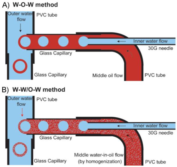
Schematic diagrams of the fluidic device for producing the A) W-O-W emulsions and B) W-W/O-W emulsions, respectively. In both cases, an aqueous PVA solution (2 wt%) was used as the inner water phase and outer continuous phase. A solution of PLGA (5 wt%) in DCM served as the middle oil phase in the W-O-W emulsion, whereas a homogenized W/O (2 wt% PVA/5 wt% PLGA, weight ratio 4:6) emulsion was used as the middle oil phase in the W-W/O-W method.
To fabricate a uniform W-O-W emulsion, the generation frequency for the primary W-O emulsion should exactly match that of the W-O-W emulsion. In other words, the inner droplets should be spaced at a uniform distance from each other in the middle oil flow, and the oil flow containing water droplets should be emulsified at the same frequency. In some cases, if these two frequencies were not matched, small satellite droplets would form, often leading to a non-uniform emulsion. When the frequency of the W-O emulsion exceeded the frequency of the W-O-Wemulsion, a W-O-W emulsion with uniform, multiple water droplets inside the oil phase would be obtained. Therefore, a precise control over the flow rates is more critical for generating the double emulsion with single droplet than the single emulsion system. The resultant W-O-W emulsion subsequently flew through the glass capillary into a collection phase (0.5 wt% PVA aqueous solution) heated to 35 °C, and were then allowed to solidify by evaporating the organic solvent. Finally, we obtained PLGA microbeads with a hollow interior and porous wall.
To control the pore structure of the wall, we employed two approaches: emulsion templating and fast evaporation of the organic solvent. In the first approach, emulsion templating was used for generating relatively large pores, where emulsion droplets evolved into the pores. Several studies have demonstrated fabrication of porous beads and films by applying this method.[21-24] As shown in Figure 1B, a W/O emulsion prepared by a homogenizer served as the middle phase instead of the pure oil phase for producing an emulsion-templated W-O-W emulsion, namely W-W/O-W emulsion. In the second approach, we used the fast evaporation of solvent to generate a porous structure due to fast precipitation of polymer dissolved in oil phase.[25] In contrast, slow evaporation of solvent leads to particles with dense structure. As a result, two different types of pores are expected: one from the templating effect of W/O emulsion and the other from fast evaporation of the organic solvent.
Figure 2 shows a typical fluorescence microscopy image of the uniform W-O-W emulsion with a diameter of 302.9 μm for the inner water phase and a thickness of 203.1 μm for the middle oil phase. The arrow indicates the layer of the middle oil phase, and the inset shows an O-W single emulsion for comparison. Water droplets (dark red) are distinctly observed within the oil droplets (red) dispersed in a continuous water phase (black). In addition, the hexagonal close packing of the W-O-W emulsion can be considered as direct evidence of good uniformity in size and shape.
Figure 2.
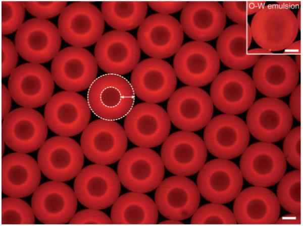
Fluorescence microscopy image of uniform W-O-W emulsions fabricated using the fluidic device. The emulsions with an aqueous interior (dark red) surrounded by the PLGA solution (red) in DCM were dispersed in the continuous water phase (black). In this case, rhodamine 6G (a hydrophobic dye) was added to the oil phase as a fluorescence probe. The flow rates for the inner water phase, middle oil phase, and outer water phase were 0.03, 0.3, and 2 mL min-1, respectively. The arrow indicates the middle oil phase and the white dotted lines indicate the boundaries between the phases. The inset depicts O-W emulsion for comparison to W-O-W emulsion. The scale bars are 200 μm.
Double emulsions are inherently less stable than single emulsion due to multiple phases and their interactions. In addition, according to the Laplace equation, the pressure inside the inner water phase is known to be higher than that of the outer water phase.[26] Therefore, to stabilize these double emulsions, water-soluble and oil-soluble surfactants are often added to the water and oil phase, respectively. In our experiments, a polymeric surfactant, poly(vinyl alcohol) (PVA), was used for the inner/outer and collection phases to stabilize the emulsion without using any oil-soluble surfactant, and at least 2 wt% PVA solution was needed to prevent coalescence of the W-O-Wemulsion. In the absence of or at low concentrations of PVA, the water droplets formed in the first glass capillary could become unstable very quickly and be converted into an O-W emulsion. In some cases, the inner water droplet dispersed in the oil phase could contact the outer water phase, thus transforming the double emulsion into a single one. It is worth pointing out that the concentration of PVA we used in our experiments exceeded the critical micelle concentration (CMC) value (around 0.36 mg L-1) of PVA.[27] This suggests that the PVA solution serve not only as the surfactant adsorbed at the interface between the water phase and the oil phase, but also as the osmotic agent to balance the pressure gradient.[26]
The diameter of the inner water phase (d) and the thickness (t) of the middle oil phase can be tuned by varying the flow rate of each phase. The effect of the flow rate of each phase on the average diameter and coefficient of variation (CV) was explored by holding the flow rate of the outer water phase at 2 mL min-1. Figure 3 shows the variation in d and t as a function of the flow rate of each phase. When the flow rate was 0.03 mL min-1 for the inner water phase and 0.3 mL min-1 for the middle oil phase, respectively, the W-O-W emulsions had a diameter of 302.9 μm (CV 1.2%) for the inner water droplet and 709.1 μm (CV 1.7%) for the overall size. In all cases, an increase in the flow rate of the inner water phase led to an increase in the diameter for the inner water droplet, accompanying by a reduction in thickness for the middle oil phase. When the flow rate of the middle oil phase was increased from 0.3 to 0.5 mL min-1, we observed a decreased diameter for the inner water droplet due to the increasing shear stress applied to the droplets, and an increased thickness for the middle oil phase. In addition, the overall outer diameter increased from 709.1 to 920.7 μm when the flow rate of the inner phases (sum of the inner water phase and the middle oil phase) increased from 0.33 to 0.57 mL min-1. This trend is consistent with the findings of our previous study when a single emulsion was involved.[18] Further increase in the flow rate for the inner phase led to the formation of W-O-W emulsions with multiple inner water droplets. For example, when the flow rate of the inner water phase was increased to 0.12 mL min-1 while keeping 0.5 mL min-1 for the middle oil phase and 2 mL min-1 for the outer water phase, an emulsion containing two water droplets was obtained. In this case, the frequency of the W-O emulsion was twice the frequency of the W-O-W emulsion. In addition to the frequency of the emulsion, the geometry of the fluidic device could also affect the frequency of the emulsion. It is expected that the frequency of the emulsion can be increased by the gravitational force intrinsic to the perpendicular geometry of the fluidic device.
Figure 3.
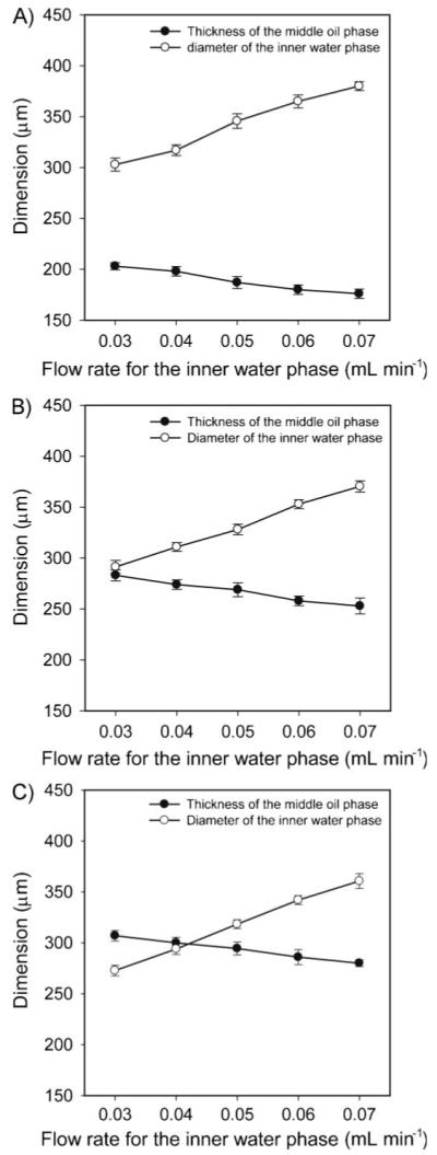
Effects of the flow rate of each phase on the average diameter (d) of the inner water droplet and thickness (t) of the middle oil phase in the W-O-W system. The flow rates for the middle oil phase were A) 0.3, B) 0.4, and C) 0.5 mL min-1. The flow rate for the outer water phase was kept at 2 mL min-1.
Figure 4 shows fluorescence microscopy images of the W-O-W emulsions generated at different flow rates for the inner water phase and the middle oil phase, which correspond to the data shown in Figure 3. These images clearly show that the dimensions of the emulsions could be conveniently tuned by varying the flow rate of each phase.
Figure 4.
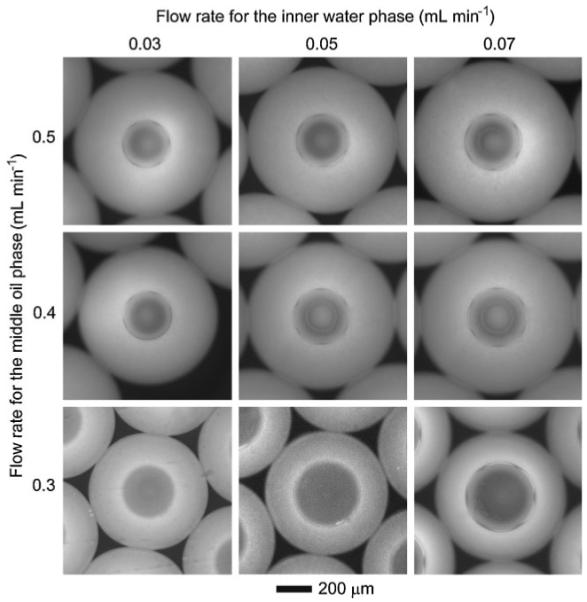
Fluorescence microscopy images (grayscale) of the W-O-W emulsions obtained at different flow rates for the inner water phase and the middle oil phase. The flow rate of the outer water phase was kept at 2 mL min-1.
Figure 5 shows SEM images of the solidified PLGA microbeads prepared using two different approaches. In the case of a W-W/O-W system, the flow rate had to be slightly adjusted to match the generation frequency of the emulsion, due to the changes in viscosity, interfacial tension, and density of the oil phase when a W/O emulsion was introduced. When the flow rates for the inner water phase, middle oil, and outer water phase were 0.035, 0.3, and 2.5 mL min-1, respectively, we could obtain a stable W-W/O-W emulsion with a single water droplet inside. As shown in Figure 5A and B, the final product showed a spherical shape with a porous structure penetrating through the outer surface, the wall, and inner surface. The average diameter of the hollow interior and thickness of the wall were 289.2 and 78.4 μm, respectively. Compared to the pristine W-O-W emulsion with d = 302.9 μm and t = 203.1 μm, there was no noticeable change in diameter for the interior, whereas the thickness of the wall was reduced significantly due to shrinkage during the evaporation of the organic solvent. The inset in Figure 5A shows the surface morphology, where pores around 1.5 μm in diameter can be seen. The development of such small pores is due to the fast evaporation of the solvent. The fast evaporation of organic solvent was achieved by using a large amount (900 mL) of heated PVA solution (35 °C) as the collection phase, because the boiling point and the solubility of DCM in water are 40 °C and 1.3 wt% (at 20 °C), respectively. Figure 5C and D shows the morphology of the microbead prepared using the W-W/O-W method, which also shows a spherical shape and porous structure penetrating through the outer and inner surfaces, as well as the wall. The diameter of the hollow interior and the thickness of the wall were 407.6 and 148.7 μm, respectively. The wall thickness of the W-W/O-W microbead was larger than that of the W-O-W microbead, which could be ascribed to the higher porosity of the wall for the W-W/O-W microbead. Note that the W-W/O-W microbead exhibited different pore morphology compared to the W-O-W microbead. As shown in the inset of Figure 5C, large pores with a diameter of about 4 μm and small pores with a diameter of less than 1 μm were observed. The small pores were caused by fast solvent evaporation and the large ones by the employment of a homogenized W/O emulsion. It was found that the small pores observed for the W-W/O-W microbeads had a smaller dimension than the pores inside the wall of W-O-W microbeads, which could be explained by the mutual saturation between the water and the solvent in W/O emulsion during homogenization.
Figure 5.
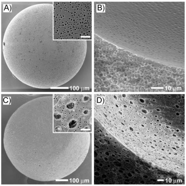
SEM images of PLGA microbeads with hollow interiors and porous walls prepared by the A,B) W-O-W method and C,D) W-W/O-W method, respectively. The outer surfaces of the microbeads are shown in (A) and (C), while the cross sections and the inner surfaces are shown in (B) and (D). The flow rates of the inner water, middle oil, and outer water phase were 0.03, 0.3, 2 mL min-1, respectively, for the W-O-W method, and 0.035, 0.3, and 2.5 mL min-1, respectively, for the W-W/O-W method. The insets in (A) and (C) are high magnifications of the outer surfaces of the microbeads, where the scale bars are 5 μm.
Figure 6 shows fluorescence microscopy images of close-packed arrays of W-O-W and W-W/O-W emulsions, where high Mw FITC-dextran (FITC-DEX) was added into the inner water phase in both cases. The insets show schematic diagrams of the microbeads prepared using each method. In Figure 6A, the inner water droplet was clearly shown with a green circular area due to FITC-DEX, whereas the oil phase did not appear. However, we could find the boundaries (as depicted by the white dotted lines) between different phases by fluorescence microscopy. On the other hand, for the W-W/O-W emulsion, the domains of the inner water phase and the middle oil phase were hardly distinguishable. This can be attributed to the rapid diffusion of FITC-DEX present in the inner water phase to the small water droplets dispersed in the oil phase. This result implies that the small water droplets in the middle oil phase were partially connected to each other during the formation of emulsion, as shown in the inset of Figure 6B.
Figure 6.
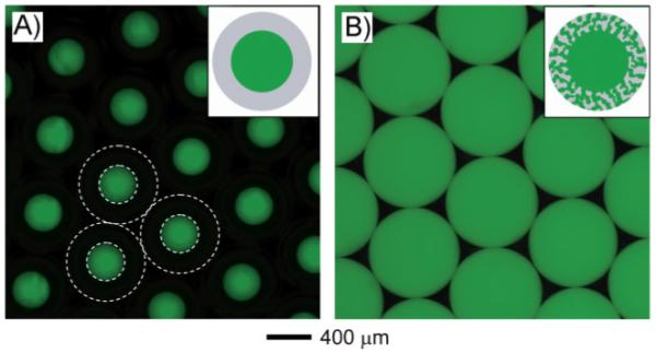
Fluorescence microscopy images of close-packed A) W-O-W emulsions and B) W-W/O-W emulsions before evaporation of the organic solvent. FITC-dextran (Mw ≈ 20 000) was included into the inner water phase as a probe dye. The white dotted lines indicate the boundaries between the phases.
The size and interconnectivity of pores are important factors for characterizing the microbeads because they determine the permeability of the microbeads.[15] To evaluate the sizes of pores and their interconnectivity, we added FITC as a low Mw (Mw ≈ 389) probe and FITC-DEX as a high Mw (Mw ≈ 20 000) probe to the inner water phase before generating the emulsion, and then used optical fluorescence microscopy to follow the diffusion of the dyes through the wall of the microbeads. Figure 7 shows fluorescence microscope images of both the W-O-W emulsion and W-W/O-W emulsion taken at different time points. As shown in Figure 7A, it was observed that the FITC within the W-O-W microbead was quickly released over time, while the FITC-DEX remained in the interior of the microbead due to its high molecular weight. The result suggests that the pores in the wall of the W-O-W microbead are interconnected, but their size is so small that only relatively small molecules can diffuse through the wall. In contrast, for the W-W/O-W microbead, the fluorescence intensity of the microbeads faded away quickly in both cases of FITC and FITC-DEX (Fig. 7B). This fast fluorescence diminution indicates that both FITC and FITC-DEX could be easily and quickly released from the porous microbeads through the enlarged pores in the wall, even though there was weak fluorescence in the last images due to physical adsorption. Therefore, it can be concluded that we obtained porous microbeads with well-interconnected and enlarged pores in the wall by employing a W/O emulsion as the template. The enlarged pores could enable free diffusion of relatively large molecules (with Mw up to at least 20 000).
Figure 7.
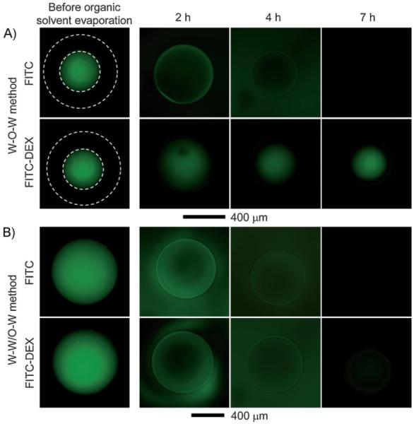
Fluorescence microscopy images of PLGA microbeads fabricated using the A) W-O-W and B) W-W/O-W method, respectively, as a function of time. After the resultant emulsions were collected with a glass Petri dish, images were taken at 2, 4, and 7 h while the solvent was removed by evaporation. FITC (Mw ≈ 389) and FITC-dextran (Mw ≈ 20 000) were used as probes by adding them into the inner water phase to evaluate the size and interconnectivity of the pores. The white dotted lines indicate the outer surface of the microbeads.
3. Conclusions
Using a simple fluidic device, we have demonstrated the production of uniform W-O-W emulsions, and ultimately uniform microbeads with a hollow interior and porous wall by employing emulsion templating in combination with fast solvent evaporation. By adjusting the flow rate of each phase, we have achieved a good control over the interior void size, the wall thickness, and the overall diameter. We believe that the dimensions of the microbeads can be further tuned by changing the capillary dimensions and device configuration. For example, if glass capillaries and needles of smaller diameters are used to fabricate the fluidic device, we should be able to obtain double emulsions with smaller sizes. The employment of emulsion templating and fast solvent evaporation could facilitate the formation of a highly porous structure in the wall. We believe that these systems can be easily extended to a variety of materials, including other hydrophobic polymers, monomers, and even hydrophilic natural polymers when O-W-O system is employed. Since this approach allows for a good control over the dimensions of the pores as well as the microbead size and wall thickness, the products can be used to encapsulate a wide range of active materials, including drugs, hormones, cosmetics, and other substances in the hollow interiors. Moreover, we believe that this technique has great potential especially for the encapsulation of living cells for controlled release and tissue engineering. In such applications, the hollow interior can provide a space for the living cells, and the well-interconnected and enlarged pore structures can serve not only as routes for the exchange of nutrients and metabolic wastes of the cells, but also as a protective barrier for the cells from the immune system. In the next step, our work will be focused on the encapsulation of living cells with the W-W/O-Wemulsion by taking advantage of the properly engineered pore structures in the wall.
4. Experimental
Materials
Poly(d,l-lactide-co-glycolide) (PLGA, 75:25, Mw ≈ 66 000-107 000, Sigma) was used as the material for the microbeads. Poly(vinyl alcohol) (PVA, Mw ≈ 13 000-23 000, 98% hydrolyzed, Aldrich) was used as the surfactant for the inner water phase, outer water phase, and collection phase. Fluorescein isothiocyanate (FITC, Mw ≈ 389, Sigma) and fluorescein isothiocyanate-dextran (FITC-DEX, Mw ≈ 20 000, Sigma) were used as hydrophilic dyes for the inner water phase, and rhodamine 6G (Mw ≈ 479, Aldrich) was used as a hydrophobic dye for the oil phase. Dichloromethane (DCM, ≥99.5%, Sigma) served as an organic solvent for PLGA. The glass microcapillary tubes were purchased from VWR international. The water used in all reactions was obtained by filtering through a set of Millipore cartridges (Epure, Dubuque, IA).
Preparation and Characterization of Microbeads Using the Fluidic Device
The microfluidic device consisted of two poly(vinyl chloride) (PVC) tubes (1/32 in. inner diameter (i.d.) × 3/32 in. outer diameter (o.d.) and 1/16 in. i.d. × 1/8 in. o.d.), two glass capillaries (0.5 mm i.d. × 0.9 mm o.d. and 0.9 mm i.d. × 1.4 o.d. mm), and a 30G needle. The fluidic device was fabricated by inserting the needle and the glass capillary (0.5 mm i.d. × 0.9 mm o.d.) into the PVC tube with smaller diameter, and then inserting the glass capillary (0.9 mm i.d. × 1.4 mm o.d.) perpendicularly into the other PVC tube, followed by sealing with epoxy adhesive (Fig. 1). The three phases—inner water phase, middle oil phase, and outer water phase—were introduced at independently adjustable flow rates by syringe pumps (KDS200, KD Scientific). Typically, an aqueous 2 wt% PVA solution was used as the inner water and outer water phase and a 5 wt% PLGA solution in DCM (with or without rhodamine 6G) was used as the middle oil phase. As for the collection phase, an aqueous 0.5 wt% PVA solution was used. To prevent clogging and precipitation during the experiment, it was noted that the introduction order of the three flows into the fluidic device should be in the following order: the outer water first, then the middle oil, and finally the inner water phase. The W-O emulsion formed at the tip of the needle flowed within the glass capillary, and W-O-W emulsions were generated at the end of the glass capillary due to the flow of the outer water phase. A typical set of the flow rates for the inner water, middle oil, and outer water phases were 0.03, 0.3, and 2 mL min-1, respectively. Finally, the resultant W-O-W emulsions were introduced into a 1 L tall beaker containing 900 mL of the collection phase heated at 35 °C, and gently stirred to facilitate solvent evaporation. In the case of the W-W/O-W system, the W/O emulsion was prepared by emulsifying an aqueous 2 wt% PVA solution and 5 wt% PLGA solution in DCM (4:6 wt. ratio) with a homogenizer (Dispenser T 10 basic, IKA works, Inc.) at 20 000 rpm for 2 min. The W/O emulsion instead of the pure oil phase was introduced as the middle phase to the same fluidic device.
To demonstrate the pore interconnectivity, two fluorescence probes, 0.3 wt% low-Mw FITC and high-Mw FITC-DEX, were added into the inner water phases for both the W-O-W and the W-W/O-W systems. The resultant emulsions were collected in a glass Petri dish and placed in a convection oven heated at 35 °C with stirring. At 2, 4, and 7 h, fluorescence microscopy images of the samples were taken and then the outer water phase was replaced by pure water of the same volume. All the fluorescence microscopy images were taken with the same shutter time.
Fluorescence microscopy (Axioskop 2, Carl Zeiss) and scanning electron microscopy (Nova NanoSEM 2300, FEI) were used to determine the dimensions of each phase in the emulsions and the morphologies of the microbeads, respectively. Average diameter and coefficient of variation (CV) of the emulsion were calculated from the fluorescence microscopy images by measuring the diameters of over 100 particles randomly selected from each sample. The value of CV is defined by CV = σ/〈M〉 × 100, where σ is the standard deviation and 〈M〉 is the average diameter. The morphologies of the inner surface and the wall of the microbeads were observed by SEM after sectioning with a sharp knife.
Acknowledgements
This work was supported in part by an NIH Director’s Pioneer Award (5DP1 OD000798) and startup funds from Washington University in St. Louis. S.W.C. was also partially supported by a Korea Research Foundation Grant funded by the Korean Government (KRF-2007-357-D00080).
References
- [1].Lee M-H, Oh S-G, Moon S-K, Bae S-Y. J. Colloid Interface Sci. 2001;240:83. doi: 10.1006/jcis.2001.7699. [DOI] [PubMed] [Google Scholar]
- [2].Ferreira LAM, Seiller M, Grossiord JL, Marty JP, Wepierre J. Int. J. Pharm. 1994;109:251. [Google Scholar]
- [3].Nakano M. Adv. Drug Delivery Rev. 2000;45:1. doi: 10.1016/s0169-409x(00)00096-x. [DOI] [PubMed] [Google Scholar]
- [4].Vasiljevic D, Parojcic J, Primorac M, Vuleta G. Int. J. Pharm. 2006;309:171. doi: 10.1016/j.ijpharm.2005.11.034. [DOI] [PubMed] [Google Scholar]
- [5].Köster S, Angilè FE, Duan H, Agresti JJ, Wintner A, Schmitz C, Rowat AC, Merten CA, Pisignano D, Griffiths AD, Weitz DA. Lab Chip. 2008;8:1110. doi: 10.1039/b802941e. [DOI] [PubMed] [Google Scholar]
- [6].Lobato-Calleros C, Rodriguez E, Sandoval-Castilla O, Vernon-Carter EJ, Alvarez-Ramirez J. Food Res. Int. 2006;39:678. [Google Scholar]
- [7].Weiss J, Scherze I, Muschiolik G. Food Hydrocolloids. 2005;19:605. [Google Scholar]
- [8].Seo M, Paquet C, Nie Z, Xu S, Kumacheva E. Soft Matter. 2007;3:986. doi: 10.1039/b700687j. [DOI] [PubMed] [Google Scholar]
- [9].Okushima S, Nisisako T, Torii T, Higuchi T. Langmuir. 2004;20:9905. doi: 10.1021/la0480336. [DOI] [PubMed] [Google Scholar]
- [10].Bocanegra R, Sampedro JL, Ganan-Calvo A, Marquez M. J. Microencapsulation. 2005;22:745. doi: 10.1080/02652040500273639. [DOI] [PubMed] [Google Scholar]
- [11].Utada AS, Lorenceau E, Link DR, Kaplan PD, Stone HA, Weitz DA. Science. 2005;308:537. doi: 10.1126/science.1109164. [DOI] [PubMed] [Google Scholar]
- [12].Huang SH, Tan WH, Tseng FG, Takeuchi S. J. Micromech. Microeng. 2006;16:2336. [Google Scholar]
- [13].Nie Z, Xu S, Seo M, Lewis PC, Kumacheva E. J. Am. Chem. Soc. 2005;127:8058. doi: 10.1021/ja042494w. [DOI] [PubMed] [Google Scholar]
- [14].Shah RK, Shum HC, Rowat AC, Lee D, Agresti JJ, Utada AS, Chu L-Y, Kim J-W, Fernandez-Nieves A, Martinez CJ, Weitz DA. Mater. Today. 2008;11:18. [Google Scholar]
- [15].Lee D, Weitz DA. Adv. Mater. 2008;20:3498. [Google Scholar]
- [16].Takeuchi S, Garstecki P, Weibel DB, Whitesides GM. Adv. Mater. 2005;17:1067. [Google Scholar]
- [17].Quevedo E, Steinbacher J, McQuade DT. J. Am. Chem. Soc. 2005;127:10498. doi: 10.1021/ja0529945. [DOI] [PubMed] [Google Scholar]
- [18].Choi S-W, Cheong IW, Kim J-H, Xia Y. Small. 2009;5:454. doi: 10.1002/smll.200801498. [DOI] [PubMed] [Google Scholar]
- [19].Barrero A, Loscertales IG. Annu. Rev. Fluid Mech. 2007;39:89. [Google Scholar]
- [20].Utada AS, Fernandez-Nieves A, Stone HA, Weitz DA. Phys. Rev. Lett. 2007;99:094502. doi: 10.1103/PhysRevLett.99.094502. [DOI] [PubMed] [Google Scholar]
- [21].Zhang H, Cooper AI. Soft Matter. 2005;1:107. doi: 10.1039/b502551f. [DOI] [PubMed] [Google Scholar]
- [22].Cooper AI. Adv. Mater. 2003;15:1049. [Google Scholar]
- [23].Fernández-Trillo F, van Hest JCM, Thies JC, Michon T, Webers-kirch R, Cameron NR. Adv. Mater. 2009;21:55. [Google Scholar]
- [24].Partap S, Rehman I, Jones JR, Darr JA. Adv. Mater. 2006;18:501. [Google Scholar]
- [25].Jeyanthi R, Thanoo BC, Metha RC, DeLuca PP. J. Control. Release. 1996;38:235. [Google Scholar]
- [26].Chang F-C, Su Y-C. J. Micromech. Microeng. 2008;18:065018. [Google Scholar]
- [27].Piirma I. Surfactant Science Series, Vol. 42: Polymeric Surfactants. 2nd ed. CRC Press; NY: 1992. p. 122. [Google Scholar]


