

Abstract
This paper describes a control architecture and intent recognition approach for the real-time supervisory control of a powered lower limb prosthesis. The approach infers user intent to stand, sit, or walk, by recognizing patterns in prosthesis sensor data in real-time, without the need for instrumentation of the sound-side leg. Specifically, the intent recognizer utilizes time-based features extracted from frames of prosthesis signals, which are subsequently reduced to a lower dimensionality (for computational efficiency). These data are initially used to train intent models, which classify the patterns as standing, sitting, or walking. The trained models are subsequently used to infer the user’s intent in real-time. In addition to describing the generalized control approach, this paper describes the implementation of this approach on a single unilateral transfemoral amputee subject, and demonstrates via experiments the effectiveness of the approach. In the real-time supervisory control experiments, the intent recognizer identified all 90 activity mode transitions, switching the underlying middle level controllers without any perceivable delay by the user. The intent recognizer also identified six activity mode transitions, which were not intended by the user. Due to the intentional overlapping functionality of the middle level controllers, the incorrect classifications neither caused problems in functionality, nor were perceived by the user.
Index Terms: Physical human-robot interaction, pattern recognition, powered prosthesis, rehabilitation robotics
I. Introduction
The knee and ankle joints of healthy individuals generate significant net power over a gait cycle during normal walking and during many other locomotive functions, including walking up stairs and slopes [1–8]. Widely available commercial transfemoral prostheses can store and/or dissipate energy, but cannot generate net power over a gait cycle. In the absence of net power, transfemoral amputees during level walking can expend up to 60% more metabolic energy relative to healthy subjects [9] and exert as much as three times the affected-side hip power and torque [7]. Presumably, a prosthesis with power generation capabilities comparable to the native limb could alleviate the need for increased exertion by the amputee during gait.
One of the primary challenges entailed in developing a powered lower limb prosthesis is the means by which the user can control the prosthesis. A powered prosthesis is fundamentally different from a passive one in that the latter can only react, while the former can both act and react. In order to effectively implement a powered prosthesis, a control interface must be developed that enables the user to control and communicate intent to the prosthesis in a real-time manner. Clearly, such a communication and control structure must be safe and reliable, and should not require cognition on the part of the user. This paper describes a control and communication structure developed by the authors for the control of powered lower limb prostheses, with the emphasis of the paper on the method developed for intent recognition.
Though no prior work exists on the development and control of a powered knee and ankle prosthesis, some prior work exists on the development and control of powered knee prostheses, and separately on powered ankle prostheses. Regarding the former, [10] describes the development of an electro-hydraulically powered knee prosthesis, developed as a laboratory test bed for studying the control of powered knee joints during walking. This prosthesis was utilized to develop an echo control approach, in which the authors instrumented the sound-side knee (of a unilateral amputee) with a position sensor, and used a modified version of the measured knee angle profile on the powered prosthesis side one half cycle later, which they term “modified echo control” [11, 12]. Ossur, a prosthetics company, recently introduced a self-contained (battery-powered) powered knee prosthesis, in which they similarly instrument the sound side leg (with accelerometers) and also utilize an echo type approach [13]. Other researchers describe the development of powered prosthesis prototypes, but do not describe a user control and communication interface structure [14, 15]. Recently, an electromyography based pattern recognizer for classifying locomotion modes using artificial neural networks and linear discriminant analysis is presented in [16]. Regarding the echo control approaches incorporated in [10–12, 17], an obvious drawback is that the sound-side (or unaffected) leg must be instrumented, which requires the user to don and doff additional instrumentation. The echo control approach presumably also restricts the use of the prosthesis to unilateral amputees and also presents a problem for “odd” numbers of steps, in which an echoed step is undesirable. A more subtle, although perhaps more significant shortcoming of the echo-type approach is that suitable motion tracking requires a high output impedance of the prosthesis, which forces the amputee to react to the limb rather than interact with it. Specifically, in order for the prosthesis to dictate the joint trajectory, it must assume a high output impedance (i.e., must be stiff), thus precluding any dynamic interaction with the user and the environment, which is contrary to the way in which humans interact with their native limbs.
Regarding powered ankle prostheses, a tibia based controller is implemented in [18], in which the ankle angle is adjusted as a function of the tibia angle. In [19], the authors use finite state controllers in combination with torque, impedance and position controllers for the control of a powered ankle prosthesis with a series elastic actuator. They also describe a neural network based high level controller which processes electromyogram (EMG) signals to manage transitions of the finite state controllers for level ground and stair descent. Note that Ossur markets an ankle prosthesis (Proprio Foot [20]) which quasistatically adjusts the ankle angle for sitting and slope walking, but does not contribute net power to gait.
This paper describes a method for the implicit communication with a powered lower limb prosthesis which is an alternative to an echo control approach. The approach infers user intent via pattern recognition based on measured data from sensors on the prosthesis, which provides several advantages relative to an echo approach. First, no additional instrumentation or wiring apart from the prosthesis need be worn by the user. Second, the information flow is much less delayed as compared to the half cycle in the echo control approach. Third, the prosthesis is decoupled from the unaffected side, and thus the user is not constrained to “even” patterns of gait. Lastly, the approach can be utilized on both unilateral and bilateral amputees.
The authors have recently reported on the development of a powered knee and ankle prosthesis which employs a finite-state based impedance control approach for control of walking [21]. This walking control structure is incorporated as a middle level controller in this paper, although in this paper, the middle level walking controller is supplemented with standing and sitting controllers. The coordination between the walking, standing and sitting middle level controllers is supervised by a high level controller which infers the user’s intent in real-time based on patterns in the prosthesis sensor data. The combined high and middle level controllers, together with a low level controller that enforces joint torques, constitute the full user control and communication interface structure through which a user can implicitly communicate with a powered lower limb prosthesis. The paper describes the structure of the supervisory controller and presents experimental results on a single amputee subject which demonstrate the effectiveness of this interface and control approach. Two videos are included in the supplemental material which qualitatively convey the performance of the approach.
II. Control Structure
A. Architecture
The control architecture for the powered lower limb prosthesis is a three level hierarchy, as diagrammed in Fig. 1. At the lowest level, closed-loop joint torque controllers compensate for the transmission dynamics. The middle level controllers, which control a given activity mode (such as walking, standing, and sitting), generate torque references for the joints using a finite state machine that modulates the impedance of the joints depending on the phase of the activity, as described in [21]. The high level controller, which is the intent recognizer, consists of three parts: the activity mode intent recognizer, the cadence estimator, and the slope estimator. The latter two estimate the slope and cadence during walking to adjust the parameters of the walking mode controller. The activity mode intent recognizer distinguishes between different activity modes such as standing, sitting, stair climbing and walking, and switches to the appropriate middle level controller. This work focuses on the activity mode controller (since the middle level control was presented in [21]), and specifically describes an activity mode intent recognition framework that uses Gaussian Mixture Models for the supervisory control of the prosthesis for activity modes of standing, sitting and walking.
Fig. 1.

Powered prosthesis control structure.
B. Finite State Based Impedance Control
In the (middle level) finite state impedance based control, the impedance behavior of healthy biomechanical gait is emulated by modulating joint impedances of the prosthesis according to the phase of gait. In each phase, the knee and ankle torques, τi, are each described by a passive spring and damper with a fixed equilibrium point, given by:
| (1) |
where ki, bi, and θki denote the linear stiffness, damping coefficient, and equilibrium point, respectively, for the ith state (or phase). Switching joint impedances between the gait phases is initiated by biomechanical cues. For instance, switching from swing extension to the early stance state during walking occurs with the detection of heel strike. With this structure, the prosthesis is guaranteed to be passive within each gait phase, and delivers power to the user only by switching the linear stiffness and the equilibrium point of the virtual spring between the phases. Such switching is a direct result of natural biomechanical cues initiated by the user. As such, the user directly and naturally controls the delivery of power from the prosthesis. The development and implementation of this control framework for level walking is presented in [21]. For the work presented herein, standing and sitting controllers were added to the walking controller (as shown in Fig. 2), and all were supervised by the intent recognizer subsequently described.
Fig. 2.

The state chart depicting the phase transitions for standing, walking and sitting modes.
The walking controller executes in a cyclical fashion over five phases. Early stance, Phase 0, is the shock absorption phase and initiated by heel strike. The leg switches to middle stance mode, Phase 1, when the ball of the foot load exceeds a predefined threshold. Middle stance is followed by late stance, when the body center of mass passes the ankle joint indicated by the angle of ankle joint. Ankle push-off defines late stance and is concluded when the foot leaves the ground. Swing phases (Phases 3 and 4) are defined by the knee flexion and extension phases of swing, respectively.
The standing impedance controller consists of two phases: weight bearing and non-weight bearing. In the weight bearing phase, the weight of the user is supported with a high impedance at the joints. In the non-weight bearing mode, the knee acts as a soft dashpot to enable freedom of movement and a smooth transition to walking. While using the standing controller, the user can shift his or her weight between the sound side and the prosthesis, balance and shuffle.
The sitting mode controller consists of four phases. Two are true sitting phases, weight bearing and non-weight bearing. The other two encompass the transition phases, sit-to-stand and stand-to-sit, for standing up and sitting down, respectively. The weight bearing and non-weight bearing phases switch the knee and ankle joints between high and low impedances, respectively. The transition phases modulate the stiffness of the knee as a function of knee angle to assist the user in standing up or sitting down. The modulation allows for smoother transitions near the seated position. The parameters of the impedance based controllers are tuned using a combination of feedback from the user and joint angle, torque and power data from the prosthesis.
C. Intent Recognition
Intent recognition was accomplished by a pattern recognizer that compares the state of the prosthesis to probabilistic models of activity. These models wee “trained” with an appropriate database, after which they were utilized for real-time intent recognition. In order to train and use such models, the appropriate input was determined. Specifically, an appropriate set of sensors was selected, an appropriate frame length for that data, and an appropriate set of features to extract from each window. Further, for purposes of real-time implementation, an appropriate reduction in data dimension was desirable. Once an appropriate input was selected, models were formulated based on a set of training data. After a probabilistic model for each activity mode (e.g., walking, standing, sitting) was established, the models were used in real-time to determine which activity was most probable at a given instant in time. In order to increase the likelihood of correct mode determination in the real-time implementation, the result was essentially low-pass filtered with a majority voting scheme. The specific procedure is described below, after which it is illustrated on a transfemoral amputee subject.
Sensor Data
The sensor data streams utilized for the intent recognizer were chosen to reflect the state of the prosthesis and the user-prosthesis interaction. Appropriate sensor information includes joint angles and angular velocities of the prosthesis joints (i.e., knee and/or ankle joints), in addition to measured interaction forces and/or torques between the user and prosthesis, and between the prosthesis and environment. Additional potentially useful sensor data includes accelerations and electromyography measurements from the residual limb.
Feature Extraction
In this work, features were extracted from frames of data, since a relatively long frame can be condensed into few information rich features. The real-time nature of the intent recognition problem requires that the features extracted from the prosthesis signals be computationally inexpensive, and as such the mean and standard deviation of each frame were used. Thus, for each sensor, two features were extracted, both of which were normalized to eliminate the scaling and dimensional disparities between the various types of sensor information.
Dimension Reduction
In order to decrease the time required to train the models, to prevent over-fitting, and to facilitate real-time implementation, the feature space was reduced (at the cost of information content). Recent work in myoelectric pattern recognition for upper limb prostheses [22] also indicates that PCA dimension reduction improves classification accuracy for a similar problem. Though multiple possibilities exist for such dimensional reduction, two effective approaches include Principal Component Analysis (PCA) [23] and Linear Discriminant Analysis (LDA) [24]. Both approaches employ linear transformations, which facilitate computational efficiency due to matrix multiplication operations. In this work, both approaches were considered.
Gaussian Mixture Model Activity Mode Classification
In this work, Gaussian Mixture Models (GMM) were used to characterize the probability that the user and prosthesis are engaged in a given activity mode. The reason for choosing GMM is twofold. Firstly, both complex and simple classifier models can be generated using GMM. For instance, a GMM classifier with two mixtures would be very similar to the simple classifiers such as Quadratic Disciminant Analysis (QDA) and LDA classifiers. The described approach takes advantage of this property of GMM and uses the number of mixtures in the GMM as a search parameter. Secondly, more complicated classifiers such as artificial neural network, support vector machine and fuzzy logic classifiers do produce black box models. The GMM outputs well defined mathematical models for the probability of each class with the weight coefficients, covariance matrices and mean vectors as parameters. This simplifies the code generation for real-time implementation of the described approach.
A separate GMM was used to describe each activity mode, wi. For some set of inputs x⃗, the probability of being in an activity mode, wi, is given by:
| (1) |
where
| (2) |
where K is the number of components of the mixture model, is the mixture parameter of the ith GMM for the kth component, which satisfy the constraints and . The mixture component, , is a multivariate Gaussian probability density function with a D × 1 mean vector, , and D × D full covariance matrix, , with D(D + 1) / 2 free parameters. Each GMM can be parameterized by K(1+ D + D(D + 1) / 2) − 1 parameters, which are the mixture parameters, mean vectors and covariance matrices, notated as . Once the GMM’s are parameterized, for a given sample feature vector, x⃗S, the activity mode, wm, was selected as the mode with the highest probability:
| (3) |
Parameterization of the GMM’s for all desired activity modes was achieved based on training data in an iterative fashion with the Expectation Maximization (EM) algorithm [25]. Several initialization schemes for EM are suggested in [26]. In this work, the reduced dataset for an activity mode, wi, was roughly clustered using the k-means algorithm [27]. These clusters were used to initialize the EM algorithm for finding the mixtures. A key factor affecting the classification performance of GMM’s is the number of mixture components, K. As such, the performance of the models for a range of mixture components was considered and compared for a given application.
D. Voting Scheme for Controller Mode Switching
The confidence with which the real-time intent recognizer switches can be increased with various types of low pass filtering. Specifically, in this work, a voting scheme was used, as subsequently described, that requires a majority agreement over a frame of samples in order to switch activity modes. Such an approach enhances confidence, but at the cost of increased switching delay, which at some point might adversely affect the communication between the user and prosthesis. As such, the trade-off between sufficient confidence and switching latency should be assessed for a given application.
III. Implementation
A. Prosthesis
The control and communication interface structure was implemented on a powered knee and ankle prosthesis, and tested on a unilateral transfemoral amputee subject. Specifically, the control approach was implemented on a self-contained, battery-powered and electric motor actuated prosthesis [28]. The powered prosthesis, which is shown in Fig. 3, is a two degree of freedom robotic device capable of generating human-scale torque and power at the knee and ankle joints. The device’s sensor package includes a custom load cell to measure the sagittal socket interface moment above the knee joint, a custom foot to measure the ground reaction force at the heel and ball of the foot, and commercial potentiometers and load cells to measure joint positions and torques, respectively. The self-contained version includes an embedded system which allows both tethered and untethered operation from either a laptop (via MATLAB Simulink) or the PIC32 onboard microcontroller, respectively. The prosthesis is powered by a 118 Watt-hr lithium polymer battery that provides approximately 1.8 hours of level ground walking at 5.1 km/hr, based on initial experiments conducted with a single unilateral transfemoral amputee subject.
Fig. 3.

Self-contained powered knee and ankle transfemoral prosthesis.
B. Subject
The prosthesis was tested on a 21-year-old male (1.93 m, 70 kg) unilateral amputee, three years post amputation. The length of the test subject’s residual limb, measured from the greater trochanter to the amputated site, was 55% of the length of the non-impaired side measured from the greater trochanter to the lateral epicondyle. The subject uses an Ottobock C-leg with a Freedom Renegade prosthetic foot for daily use. The subject’s daily use socket was used for the experiments, where the powered prosthesis prototype was attached in place of the daily use prosthesis. The overall prosthesis height adjustment and varus-valgus alignment were performed by a licensed prosthetist. The study described herein was approved by the Vanderbilt Institutional Review Board, and the subject signed an informed consent prior to participation in the study.
C. Intent Recognizer Training and Model Selection
The general structure of the intent recognizer, which is illustrated in Fig. 4, consists of generating data frames of appropriate sensors, taking the mean and standard deviation of each frame, reducing the dimensionality of these features, using trained models to determine the highest probability class, and using an averaging approach to increase confidence. As previously mentioned, several specific features of this structure are application-dependent, including the set of sensors to use, the length of the data windows, the number of components in the mixture models, and the length of the voting vector. The sensor signals used as input to the intent recognizer consists of seven signals, which include the joint angles and angular velocities of the knee and ankle, socket sagittal plane moment, and heel and ball of foot forces. Note that the joint angles and angular velocities characterize the internal state of the prosthesis, while the forces and torques contain information regarding interaction with the user and environment. At each time step of activity mode intent recognition (10 ms), frames are generated from each sensor signal and the (normalized) average and standard deviation are computed, such that the full feature set includes 14 variables. The frame length, dimensionality of the reduced feature set, method for dimension reduction, number of model components, and voting vector length are all application-dependent trade-offs.
Fig. 4.

Block diagram of the activity mode intent recognizer.
In the implementation discussed below, the dimensionality of the reduced feature set, the method of reduction, and the number of components in the mixture model were all determined by selecting the combination that provided the best accuracy of classification for the database that characterized the various activity modes. The frame length and voting vector lengths were then determined as the combination that provided the smallest total delay with a 100% success rate on a given set of test data. This process, and the resulting implementation, is described in the following sections.
Database Generation
In order to train the GMM’s and to select the appropriate options in the intent recognition structure, a database of sensor data was collected to characterize the various activity modes of interest. Specifically, the powered prosthesis was tethered to a laptop computer running MATLAB Real Time Workshop for controller implementation and the middle-level prosthesis controllers were tuned for the subject for walking, standing and sitting. A database was generated that contained the possible walking, standing and sitting scenarios as outlined in Table I. Generation of the database took approximately 2 hours. It should be noted that the presented intent recognition approach is based on mechanical sensors, which do not change their behavior significantly over time. Therefore, after the initial two hour training period, the intent recognizer should only need to be re-trained after major adjustments (e.g., realignment by a prosthetist, or re-tuning of the middle-level control parameters), since the general characteristics of the user gait does not in general change significantly.
TABLE I.
Different Activity Scenarios For Database Generation
| Scenario | Num. of trials | Activity Mode | Activity | Purpose |
|---|---|---|---|---|
| 1 | 4 | Walking | Slow walking with walking controller | GMM, OVVL |
| 2 | 4 | Walking | Normal walking with walking controller | GMM, OVVL |
| 3 | 4 | Walking | Fast walking with walking controller | GMM, OVVL |
| 4 | 4 | Walking | Walking with standing controller | GMM, OVVL |
| 5 | 4 | Standing | Standing with walking controller | GMM, OVVL |
| 6 | 4 | Standing | Static standing with standing controller | GMM, OVVL |
| 7 | 4 | Standing | Dynamic standing with standing controller | GMM, OVVL |
| 8 | 15 | Sitting | Standing up | GMM |
| 9 | 15 | Sitting | Sitting down | GMM |
| 10 | 2 | Sitting | Sitting | OVVL |
GMM stands for the task of designing the GMM classifier. OVVL stands for the task of finding the optimal voting vector length for real-time controller switching.
All data was sampled at 1000 Hz, which provides real-time reconstruction of information up to approximately 100 Hz. Note that generation of the features (mean and standard deviation of the frames) is not computationally expensive, and thus 1000 Hz sampling does not significantly tax the microcontroller. For the standing mode, two activities were considered: static and dynamic standing. The former consists of activities in which the feet do not leave the ground, such as standing stationary and shifting weight between the limbs. The latter contains more active movements, such as taking small steps, turning in place, and repositioning the limb. Walking includes slow, normal and fast walking with the respective middle level walking controllers. For each walking and standing scenario outlined in Table I, four 100-second trials were measured. Of these, the first two trials were used for model training, while the second two were used for performance evaluation of the intent recognizer.
In order to recognize standing and walking modes, the database generated must contain the possible matched and unmatched activity modes. Specifically, a matched activity mode is when the activity corresponds to the current control mode (e.g., standing while the prosthesis is in standing mode), while an unmatched mode is when the activity corresponds to a different control mode (e.g., walking while the prosthesis is in standing mode). Fig. 5 illustrates the timing of mode transitions and makes clear why such unmatched datasets are required for proper intent recognition.
Fig. 5.

Demonstration of the controller and real mode discrepancy during mode transitions.
Generation of the database for the sitting mode is more complicated, since the finite state based impedance controller for sitting includes the standing up and sitting down transitions. These transitions are initiated by the intent recognizer. Without a database containing these transitions, the intent recognizer cannot be designed. In order to overcome this problem, the standing up and sitting down transitions were triggered using knee angle thresholds for generating the database. In order to generate the sit-to-stand database, the activity mode change was artificially triggered when the knee angle became less than 5 degrees. In order to generate the stand-to-sit database, the activity mode was artificially switched to sitting mode when the knee angle exceeded 5 degrees. Fifteen trials for both cases were conducted. The four seconds after the sitting down transition and four seconds before the standing up transition were recorded for generating the sitting feature frames for the GMM classifier design. From each trial 20 frames of length 50, 100, 200 and 400 samples were generated. Moreover, two 100-second sitting trials were recorded for finding the optimal voting vector length for sitting to standing transitions. During these trials, the subject sat on a stool, performed sitting activities such as repositioning limbs, changing orientation, and reaching an object excluding standing up transition. For each frame length, the database for the GMM classifier design included 1600, 1200, and 600 frames of walking, standing and sitting modes, respectively.
Model Selection
The model search space consisted of 30 models, which were the combinations of 6 dimension reduction methods (i.e., PCA and LDA for 1 to 3 dimensions) applied to 5 GMM models with number of components K ranging from 2 to 6, for each frame length. In order to find the best classifier for each frame length, the Area under the Receiver Operator Characteristics (AUC) curve [29] was used as the performance metric. This metric was used because it provides a comprehensive metric that computes true and false positives for all possible classification thresholds observed in the data, and because it is insensitive to class distribution. For adapting the AUC score to the multidimensional case, the scores between different classes were computed and the average was used as the final score for a specific model. Ten-fold cross-validation (CV) [30] was employed to avoid over-fitting. In ten-fold CV, the data is split into ten sets of size N /10 each. For purposes of model selection, the classifier was trained on 9 datasets and tested for the AUC on the remaining one. This was repeated ten times until all the data splits were tested and the mean AUC score was recorded as the performance metric for a specific classifier.
Voting Scheme for Controller Mode Switching
The real-time implementation of the voting scheme consists of overlapping frames that are classified at each 10 ms interval (Δt). In the voting scheme, the last l classifier decisions are stored in a voting vector and mode switching occurs if more than 80 percent of the classification results are in agreement. The activity mode switching logic based on the voting scheme for the walking, standing and sitting modes is demonstrated in Fig. 6. To avoid chattering during transition and increase the robustness of the powered prosthesis control, a rule was introduced to prevent mode switching for 500 ms after the most recent mode switching occurs (i.e., it is assumed a user does not enter and leave a given activity mode in 500 ms).
Fig. 6.

Controller mode switching logic for gait mode intent recognition.
The combination of the voting length l and the frame length f determines the total delay of activity mode intent recognition. To minimize the total delay in the intent recognizer, the last two trials for each scenario in the experimental database were used to select the minimum voting vector length, corresponding to each frame length, that resulted in no incorrect classifications in the two test trials. In this process, the real-time activity intent recognizer was implemented (offline) with possible voting vector length from 10 to 100 in increments of 5. For each activity mode and for each of the four frame lengths f, the voting vector length was increased until the intent recognizer provided 100% accuracy in the two test trials. Once the optimal voting lengths for each frame size were found, the best frame length/voting vector length combination was determined as that which yielded the smallest overall delay d, where d = f/2+10 lmax, where lmax is the greatest voting vector length determined among the four transitions shown in Fig. 6.
IV. Results and Discussions
PCA versus LDA for Dimension Reduction
PCA and LDA reduced datasets for the frame length 200 are shown in Fig. 7. The inherent characteristics of the transforms are apparent in the figures. Specifically, PCA essentially maximizes the variance of the data, while LDA generates ellipsoid clusters for different classes by maximizing the distance between different class clusters and minimizing the in-class variances. One might think that LDA dimension reduction would result in better classification results compared to PCA, since LDA takes into account the labels of the classes. As stated by [31], however PCA may outperform LDA when the inherent distribution of the data is non-normal. In [32], the authors report that PCA outperformed LDA for the intent recognition between standing and walking classes for a three-dimensional reduction, which was a binary classification problem. In the present three-class problem, LDA outperforms PCA in all cases. As an example, Fig. 8 shows the mean AUC scores for both PCA and LDA reduced GMM classification for the frame length 200.
Fig. 7.
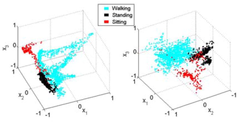
PCA (left) and LDA(right) dimension reduced features extracted from 200 sample-long frames.
Fig. 8.

Classification performance of different model order GMM’s with PCA and LDA dimension reduction to one (a), two (b) and three (c) dimensions for frame length. Note the y-axis scaling for each dimension.
Gaussian Mixture Model Selection
The best AUC scores are obtained from the LDA dimension-reduced three-dimensional GMM’s with 5, 6, 5, and 4 mixtures for the frame lengths 50, 100, 200 and 400, respectively. It is observed that the best AUC score increases with increasing frame length. Surface plots of the standing and walking mixture models for frame length 100, showing the portions of the feature space with greater than 0.05 probability densities are presented in Fig. 9. The distinct locations of the three different activities in the reduced feature space can be seen in this figure. The dynamic nature of walking is observed in the walking mixture model, which creates a three dimensional loop consisting of several ellipsoids of areas with high probability density. The standing up and sitting down transitions are bridge-like volumes connecting the standing and sitting modes. Lastly, the standing mixture model resides in a small region of the reduced feature space, which connects the walking and sitting regions.
Fig. 9.

Gaussian Mixture Models surface plots for standing, walking and sitting showing the portions of the feature space, where probability density function is greater than 0.05, for three dimensional LDA reduced data.
Voting Vector Length Selection
As previously described, the first two trials of each dataset were used to train the mixture models, while the last two trials were used to select the voting vector lengths that correspond to a minimum total delay and 100% accuracy (in the last two trials). The minimum voting vector lengths that correspond to 100% accuracy are 55, 45, 65, and 60, respectively, which correspond to frame lengths of 50, 100, 200 and 400, respectively, and GMM models of 5, 6, 5, and 4 components, respectively. These and the respective approximate intent recognition delay for each frame length is listed in Table II. As can be observed from the table, the shortest approximate delay for the intent recognition is obtained for the frame length 100 (which corresponds to a voting vector length of 45 and 6-component GMM. With this combination, the intent recognizer switches to a new mode in approximately one half a second.
TABLE II.
Approximate Intent Recognition Delays for Different Frame Lengths
| Frame Length | Frame Delay (ms) | Voting Delay (ms) | Total Delay (ms) |
|---|---|---|---|
| 50 | 25 | 550 | 525 |
| 100 | 50 | 450 | 500 |
| 200 | 100 | 650 | 750 |
| 400 | 200 | 600 | 800 |
For EMG-controlled upper limb prostheses, it is stated in that the maximum latency without a perceivable delay is 300 ms [33]. Therefore, one might argue that the half a second approximate delay for the lower limb intent recognition is too long. The described intent recognition problem, however, is different in comparison to the one in the EMG-controlled upper limb prostheses. Realistically, no latency is allowed for the control of the powered lower limb prostheses. Therefore, the middle layer controllers which govern the dynamics of the system for specific activities such as walking, standing, or sitting switch between different phases using biomechanical cues measured directly by the mechanical sensors of the prosthesis. For the supervisory control described in this paper, the negative effects of latency are alleviated by designing the middle layer controllers such that in the switching regions the controllers exhibit overlapping functionality. For instance, the middle stance phase of the walking controller and the weight-bearing phase of the standing controller both exhibit similar impedance properties. Therefore, the subject can stand using both controllers but the standing with the standing controller is more comfortable because it is specifically designed for that purpose. The authors are not aware of any analytical method for computing the maximum allowable latency for this device. Nonetheless, the described approach tries to create the most robust controller with the least amount of delay. The maximum allowable latency is tested in real-time supervisory control experiments and the subject stated that he does not have any perceived latency in his actions.
Real-Time Supervisory Control
The intent recognition structure with the selected components (three dimensional LDA dimension reduction with GMM with 6 mixtures using 100 sample-long frames and voting vector length of 45) was tested in real-time activity mode intent recognition. Three trials lasting 190 seconds each on a treadmill were conducted to verify that the method works in a closed feedback loop as a supervisory controller. A video showing one of these trials (corresponding to the data in Fig. 10) is included in the supplemental material. Each trial began with the test subject standing on a treadmill. The treadmill was started and stopped at arbitrary intervals several times during the trials, requiring the test subject to switch between walking and standing. Note that standing included shifting weight from one side to the other and turning in place. During some of the periods when the treadmill was stopped, a stool was placed on a treadmill and the subject volitionally transitioned between standing and sitting. During these trials, 56 activity mode transitions were made by the subject, and all 56 were correctly identified by the intent recognizer, with no user-perceived latency in mode switching. Despite this, the intent recognizer identified three activity modes during the 570-second trial period that were not intended by the user. Specifically, during the standing mode, the intent recognizer once identified intent to walk, and twice identified intent to sit (and in both cases switched back within one second). Though such incorrect inferences may sound potentially dangerous, they in fact are benign, and in these cases were not noticed by the user. Specifically, as can be seen in Fig. 10, when casually shifting weight between legs during standing, the distinction between standing, walking, and the initial transition state from standing to sitting are all quite similar in state and in desired functionality (i.e., both the state of the leg and its behavior are non-unique). That is, the switching errors occurred in a region of the feature space in which both the movement patterns and the leg impedances are similar, and thus they have little significant effect. For instance, the impedance behavior of the prosthesis for the stand to sit transition is defined by a stiff spring with an equilibrium point of 5 degrees. The virtual spring in the weight bearing standing mode is set to 0 degrees and has a similar stiffness. When the prosthesis makes an erroneous mode switch from standing to sitting, the impedance behavior of the prosthesis does not change significantly. As such, the distinction between these modes is somewhat artificial, and thus there is little importance in distinguishing between them. Thus, the apparent confusion of the intent recognizer is more a problem with the non-uniqueness of these respective activity modes than with a misunderstanding of the user’s intent.
Fig. 10.

Real-time activity mode switching (top), knee angle (middle) and ground reaction force (bottom) for a 190 seconds long trial. A video corresponding to this trial is included in the supplemental material.
An example of an erroneous mode switch is shown in the trial of Fig. 10, which shows the activity mode, knee angle and ground reaction force for a 190-second trial, with an erroneous stand-to-sit transition at approximately 130 seconds. Note that the video clip included in the supplemental material corresponds exactly to the 190-second trial shown in Fig. 11, and thus this misclassification of user intent is also captured in the video (although there is no ostensible visual evidence of the incorrect switching).
Fig. 11.

Knee angle (top) and real-time activity mode switching (bottom) for a 90 seconds sit to stand and stand to sit trial.
One of the advantages of the intent recognition approach using mechanical sensors is that the database generation does not need to be frequently repeated. In order to test this, three additional trials lasting 110 seconds wee conducted in another experimental session on a different day. During these trials, 34 activity mode transitions were made by the subject, and all 34 were correctly identified by the intent recognizer, again with no user-perceived latency in mode switching. Despite this, the intent recognizer identified three activity modes during the 330-second trial period that were not intended by the user.
One might argue that a simple thresholding scheme such as that implemented for the sitting database generation might suffice for switching between different controllers. The knee angle and the activity mode from a trial during which the subject stood (and shuffled) and made stand-to-sit and sit-to-stand transitions is shown in Fig. 11. As can be observed from the figure, the knee angle threshold used for generating the database (5 degrees) is exceeded couple of times during dynamic standing. If this threshold were used, incorrect stand-to-sit transitions would be initiated. In general, the intent recognizer creates an intricate switching function combining many measurements which results in a robust supervisory controller.
The robustness of the intent recognition was tested with respect to weight change of the user, since the intent recognition approach uses mechanical sensors including the ones measuring the ground reaction force. In this scenario, the subject walked, occasionally stopping to stand (including shuffling) while carrying objects with different weights. The subject carried separately a 9 kg backpack and an 8 kg briefcase and then carried both objects together amounting to approximately 20 percent of subject’s body weight. The subject stated that the weight of these objects were greater than the ones he would carry in daily use. The subject stated that the switch from standing to walking controller occurred earlier with increasing weight. It is seen that the intent recognizer worked without any problems for these scenarios. A video corresponding to this trial is included in the supplemental material.
Though the described method requires significant computation during the training phase (i.e., generating GMM’s for all the combinations, CV and frame length optimization), real-time implementation does not require extensive computation. The entire powered prosthesis control system (lower and middle level controllers, along with the intent recognizer) implemented in real-time using Matlab Real-Time Workshop requires approximately 10% processor utilization for a Pentium 4, 2.0 GHz desktop computer. It should be noted that in real-time implementation, the computation required by the algorithm scales linearly with the addition of other activity modes, such as stair ascent/descent, and thus should allow real-time implementation on an embedded microcomputer with more limited resources.
V. Conclusion
The authors present an activity mode intent recognition framework for a powered lower limb prosthesis which uses only signals from the prosthesis. The authors describe the approach, and demonstrate it on a powered knee and ankle prosthesis. For this prosthesis, LDA dimension reduction with 100 sample-long frames yielded the best results for standing, sitting and walking mode recognition using GMM as a classifier. Experiments with a unilateral amputee subject showed that the activity mode intent recognition framework extracts the user intent in real-time and switches to the correct underlying activity controller. Some classification errors were observed, although only in highly similar types of activity, and thus the errors in switching were not problematic and were not perceived by the user.
Future work includes testing the described framework with multiple amputee subjects and adding new activity modes such as stair ascent and descent.
Supplementary Material
Acknowledgments
This work was supported by the National Institutes of Health grant no. R01EB005684-01.
Biographies

Huseyin Atakan Varol (S’01-M’09) received the B.S. degree from Sabanci University, Istanbul, Turkey, in 2005 in mechatronics engineering. He received the M.S. and Ph.D. degrees both in electrical engineering from Vanderbilt University, Nashville, TN, in 2007 and 2009, respectively.
He is currently a Research Associate at the Department of Mechanical Engineering, Vanderbilt University, Nashville, TN. His current research interests include biomechatronics with an emphasis on lower-limb prostheses, control, signal processing, machine learning and embedded systems.

Frank Sup (S’06 - M’09) received the B.S. degree from the University of Illinois at Urbana Champaign, in 2001. He received the M.S. and Ph.D. degrees both in mechanical engineering from Vanderbilt University, Nashville, TN, in 2006 and 2009, respectively.
He is currently a Research Associate at the Department of Mechanical Engineering, Vanderbilt University, Nashville, TN. His current research interests include the design, control and testing of lower-extremity prostheses, embedded systems and robotics.

Michael Goldfarb (S’93–M’95) received the B.S. degree in mechanical engineering from the University of Arizona, Tucson, in 1988, and the S.M. and Ph.D. degrees in mechanical engineering from Massachusetts Institute of Technology, Cambridge, in 1992 and 1994, respectively.
Since 1994, he has been with the Department of Mechanical Engineering, Vanderbilt University, Nashville, TN, where he is currently the H. Fort Flowers Professor of Mechanical Engineering. His current research interests include the design and control of advanced upper and lower extremity prostheses and gait restoration for spinal cord injured persons.
Footnotes
This paper has supplementary downloadable multimedia material available at http://ieeexplore.ieee.org, provided by the author. This material includes two videos (IEEEBIOMED_intent_video.wmv and IEEEBIOMED_intent_withweight_video.wmv) demonstrating real-time supervisory control experiments using intent recognition with the Vanderbilt powered knee and ankle prosthesis worn by a transfemoral amputee subject. The videos can be played with Windows and their sizes are 39 MB and 16 MB, respectively.
Contributor Information
Huseyin Atakan Varol, Email: atakan.varol@vanderbilt.edu.
Frank Sup, Email: frank.sup@vanderbilt.edu.
References
- 1.DeVita P, Torry M, Glover KL, Speroni DL. A functional knee brace alters joint torque and power patterns during walking and running. J of Biomechanics. 1996 May;29(5):583–588. doi: 10.1016/0021-9290(95)00115-8. [DOI] [PubMed] [Google Scholar]
- 2.Jacobs R, Bobbert MF, van Ingen Schenau GJ. Mechanical output from individual muscles during explosive leg extensions: The role of biarticular muscles. J of Biomechanics. 1996 Apr;29(4):513–523. doi: 10.1016/0021-9290(95)00067-4. [DOI] [PubMed] [Google Scholar]
- 3.Nadeau S, McFadyen BJ, Malouin F. Frontal and sagittal plane analyses of the stair climbing task in healthy adults aged over 40 years: what are the challenges compared to level walking? Clinical Biomechanics. 2003 Dec;18(10):950–959. doi: 10.1016/s0268-0033(03)00179-7. [DOI] [PubMed] [Google Scholar]
- 4.Nagano A, Ishige Y, Fukashiro S. Comparison of new approaches to estimate mechanical output of individual joints in vertical jumps. J of Biomechanics. 1998 Oct;31(10):951–955. doi: 10.1016/s0021-9290(98)00094-3. [DOI] [PubMed] [Google Scholar]
- 5.Prilutsky BI, Petrova LN, Raitsin LM. Comparison of mechanical energy expenditure of joint moments and muscle forces during human locomotion. J of Biomechanics. 1996 Apr;29(4):405–415. doi: 10.1016/0021-9290(95)00083-6. [DOI] [PubMed] [Google Scholar]
- 6.Riener R, Rabuffetti M, Frigo C. Joint powers in stair climbing at different slopes. Proc. of the First Joint BMES/EMBS Conf., vol. 1; 1999. p. 530. [Google Scholar]
- 7.Winter D. The Biomechanics and Motor Control of Human Gait: Normal, Elderly and Pathological. 2. University of Waterloo Press; 1991. [Google Scholar]
- 8.Winter DA, Sienko SE. Biomechanics of below-knee amputee gait. J of Biomechanics. 1988;21(5):361–367. doi: 10.1016/0021-9290(88)90142-x. [DOI] [PubMed] [Google Scholar]
- 9.Waters RL, Perry J, Antonelli D, Hislop H. Energy cost of walking of amputees - Influence of level of amputation. J of Bone and Joint Surgery-American Vol. 1976;58(1):42–46. [PubMed] [Google Scholar]
- 10.Flowers WC, Mann RW. Electrohydraulic knee-torque controller for a prosthesis simulator. ASME J of Biomechanical Engineering. 1977;99(4):3–8. doi: 10.1115/1.3426266. [DOI] [PubMed] [Google Scholar]
- 11.Stein JL Massachusetts Institute of Technology. Dept. of Mechanical Engineering. Massachusetts Institute of Tech. Dept. of Mechanical Eng. Thesis Ph.D. 1983. Design issues in the stance phase control of above-knee prostheses. [Google Scholar]
- 12.Grimes DL. Massachusetts Institute of Tech. Dept. of Mechanical Eng. Thesis Ph.D. 1979. An active multi-mode above knee prosthesis controller. [Google Scholar]
- 13.Bedard S, Roy P. Actuated Leg Prosthesis for Above-Knee Amputees. U. S. Patent. 2003
- 14.Martinez- Villalpando E, Weber J, Elliott G, Herr H. Design of an agonist-antagonist active knee prosthesis. Proc. IEEE/RAS-EMBS Int. Conf. on Biomedical Robotics and Biomechatronics; 2008. pp. 529–534. [Google Scholar]
- 15.Popovic D, Schwirtlich L. Belgrade active A/K prosthesis. In: de Vries J, editor. Electrophysiological Kinesiology, Intern. Congress Ser. No. 804, Excerpta Medica; Amsterdam, The Netherlands. 1988. pp. 337–343. [Google Scholar]
- 16.Huang H, Kuiken TA, Lipschutz RD. A Strategy for Identifying Locomotion Modes Using Surface Electromyography. IEEE Trans on Biomedical Engineering. 2009 Jan;56(1):65–73. doi: 10.1109/TBME.2008.2003293. [DOI] [PMC free article] [PubMed] [Google Scholar]
- 17.Bedard S, Roy P. Actuated leg prosthesis for above-knee amputees. 7,314,490. U. S. Patent. 2003 June 17;
- 18.Holgate MA, Bohler AW, Sugar TG. Control algorithms for ankle robots: A reflection on the state-of-the-art and presentation of two novel algorithms. Proc. IEEE/RAS-EMBS Int. Conf. on Biomedical Robotics and Biomechatronics; 2008. pp. 97–102. [Google Scholar]
- 19.Au S, Berniker M, Herr H. Powered ankle-foot prosthesis to assist level-ground and stair-descent gaits. Neural Networks. 2008 May;21(4):654–666. doi: 10.1016/j.neunet.2008.03.006. [DOI] [PubMed] [Google Scholar]
- 20.Koniuk W. Self-adusting prosthetic ankle apparatus. 6,443,993. U. S. Patent. 2001 March 23;
- 21.Sup F, Bohara A, Goldfarb M. Design and control of a powered transfemoral prosthesis. Int J of Robotics Research. 2008 Feb;27(2):263–273. doi: 10.1177/0278364907084588. [DOI] [PMC free article] [PubMed] [Google Scholar]
- 22.Hargrove LJ, Li GL, Englehart KB, Hudgins BS. Principal Components Analysis Preprocessing for Improved Classification Accuracies in Pattern-Recognition-Based Myoelectric Control. Ieee Transactions on Biomedical Engineering. 2009 May;56(5):1407–1414. doi: 10.1109/TBME.2008.2008171. [DOI] [PubMed] [Google Scholar]
- 23.Jolliffe IT. Principal Component Analysis. 2. New York: Springer; 2002. [Google Scholar]
- 24.Fisher RA. The statistical utilization of multiple measurements. Annals of Eugenics. 1938;8:376–386. [Google Scholar]
- 25.Dempster AP, Laird NM, Rubin DB. Maximum likelihood from incomplete data via EM algorithm. J of the Royal Statistical Society Series B-Methodological. 1977;39(1):1–38. [Google Scholar]
- 26.McLachlan GJ, Peel D. Finite mixture models. New York: Wiley; 2000. [Google Scholar]
- 27.Hartigan JA, Wong MA. A K-means clustering algorithm. Applied Statistics. 1979;28(1):100–108. [Google Scholar]
- 28.Sup F, Varol HA, Mitchell J, Withrow TJ, Goldfarb M. Self-Contained Powered Knee and Ankle Prosthesis: Initial Evaluation on a Transfemoral Amputee. IEEE 11th Int. Conf. on Rehabilitation Robotics; 2009. pp. 638–644. [DOI] [PMC free article] [PubMed] [Google Scholar]
- 29.Fawcett T. An Introduction to ROC Analysis. Pattern Recognition Letters. 2006 Jun;27(8):861–874. [Google Scholar]
- 30.Mitchell TM. Machine Learning. New York: McGraw-Hill; 1997. [Google Scholar]
- 31.Martinez AM, Kak AC. PCA versus LDA. IEEE Trans on Pattern Analysis and Machine Intelligence. 2001 Feb;23(2):228–233. [Google Scholar]
- 32.Varol HA, Sup F, Goldfarb M. Real-time gait mode intent recognition of a powered knee and ankle prosthesis for standing and walking,” Proc. IEEE/RAS-EMBS Int. Conf. on Biomedical Robotics and Biomechatronics; 2008. pp. 66–72. [DOI] [PMC free article] [PubMed] [Google Scholar]
- 33.Englehart K, Hudgins B. A robust, real-time control scheme for multifunction myoelectric control. Ieee Transactions on Biomedical Engineering. 2003 Jul;50(7):848–854. doi: 10.1109/TBME.2003.813539. [DOI] [PubMed] [Google Scholar]
Associated Data
This section collects any data citations, data availability statements, or supplementary materials included in this article.