Abstract
The porous polymer monoliths went a long way since their invention two decades ago. While the first studies applied the traditional polymerization processes at that time well established for the preparation of polymer particles, creativity of scientists interested in the monolithic structures has later led to the use of numerous less common techniques. This review article presents vast variety of methods that have meanwhile emerged. The text first briefly describes the early approaches used for the preparation of monoliths comprising standard free radical polymerizations and includes their development up to present days. Specific attention is paid to the effects of process variables on the formation of both porous structure and pore surface chemistry. Specific attention is also devoted to the use of photopolymerization. Then, several less common free radical polymerization techniques are presented in more detail such as those initiated by γ-rays and electron beam, the preparation of monoliths from high internal phase emulsions, and cryogels. Living processes including stable free radicals, atom transfer radical polymerization, and ring opening metathesis polymerization are also discussed. The review ends with description of preparation methods based on polycondensation and polyaddition reactions as well as on precipitation of preformed polymers affording the monolithic materials.
Keywords: Monolith, Polymerization, Radical, Polycondensation, Grafting
1. Introduction
Monolithic columns in their current incarnation have been known for about two decades. Although this age is short compared to over 100 years of chromatography [1], they have already made a significant impact on the separation science. Meanwhile, tens of review articles e.g. [2-26] and one book [27] have been published on this topic. Guiochon published recently an excellent overview describing the use of monolithic columns in liquid chromatography [21]. Despite the large number of these reviews compiling various aspects of the monolithic technology, none of them focuses in detail on the vast variety of methods enabling the preparation of monoliths the less then of monoliths based on synthetic polymers. This review article is written to fill this gap and to arm those who are entering this field with ammunition for a rapid success. In addition, representing a number of papers published in journals that are typically below the radar screen of chromatographers, the following text may also become an inspiration for them since many interesting and sometimes exotic techniques and monolith did not materialize in any separation device yet.
2. Short excursion in history
The attempts at separation media formed from a single piece of material percolate through the scientific literature for more than 50 years. They were first mentioned in the early 1950s as emanating from theoretical discussions of Nobel Prize laureates Synge, Martin, and Tiselius [28] but soon disappeared from the screen since gel-like materials that were available at that time would collapsed under hydrostatic pressure needed to achieve flow [29]. Less successful experiments with synthetic hydrogels were carried out later, and confirmed these theoretical assumptions [30]. More rigid open pore polyurethane foams exhibited a certain potential in both LC and GC separations [31-33] but did not find any resonance within the chromatographic community. Thus, the legitimate “monolithic age” starts at the verge of the 1990s.
Hjertén prepared a highly swollen crosslinked gel by polymerization of aqueous solutions of N,N′-methylenebisacrylamide and acrylic acid in the presence of a salt, typically ammonium sulfate, in an aqueous medium. The next step was a compression of this polymer to a small fraction of its original volume in order to completely fill the cross section of the column. Surprisingly, this column exhibited very good permeability to flow [34]. He then called this separation medium continuous bed. In reality, the gel obtained by polymerization does not appear to be a real monolith, i.e. a single piece of material, since one of his next reports described preparation of the gel polymer in a test tube. The product was then diluted with water prior to “packing” in the column tube and compression [35]. Since continuous crosslinked gel cannot be dispersed in a liquid, this fact indicates that the product of this polymerization had a particulate character and only the compression affords the desired monolith-like structure.
At the same time, we were copolymerizing glycidyl methacrylate and ethylene dimethacrylate mixed with porogenic solvents in a mold and obtained monolithic blocks of porous highly crosslinked polymers. Although the first monoliths of this type were produced from mixtures typical of the preparation of macroporous beads, surprisingly their pore size distribution was completely different. Discs cut from these monolithic plates and modified with diethylamine were highly permeable and allowed the very fast separations of proteins [36,37]. This layer-like technology was then extended to an entirely new format - monolithic chromatographic columns prepared in situ within the confines of standard stainless steel columns [38].
The final contribution to the family of different monolithic technologies has been added by Tanaka in the mid 1990s [39,40]. Knowing well silica, the most popular inorganic material widely used in liquid chromatography, and in collaboration with materials scientists in Kyoto, they designed a process that afforded silica-based monoliths with controlled porous properties. The in situ preparation of typical analytical size columns is difficult due to the significant shrinkage of silica occurring during the polycondensation reaction, aging, and heat treatment. Therefore, they encased the preformed monolith in a plastic holder to obtain chromatographic column. Fields was the first to prepare a silica-based capillary column via in situ solidification of formamide solution of potassium silicate [41]
All three approaches shown in this section have later been adopted by the industry and the monolithic columns are now commercially available. More importantly, these early efforts also inspired a large number of groups worldwide to innovative research thus moving the field rapidly forward.
3 Free radical processes
3.1 Thermally initiated polymerization
Thermally initiated free radical polymerization was the first method used for the preparation of rigid polymer-based monolith [34,36-38]. This process is very simple and its origin can be traced down to techniques typically used for the preparation of porous beads using suspension polymerization. This type of polymerization is generally treated in the literature as a “clone” of bulk polymerization in which each droplet of the dispersed phase containing monomer is an individual bulk reactor [42]. Therefore, one might have anticipated that the properties of the products of both suspension and bulk polymerizations would be nearly identical. Surprisingly, our initial experiments revealed that this was not the case and pore size distributions of both formats were actually entirely different. Fig. 1 shows the considerable discrepancy that exists between the pore size distributions of macroporous poly(glycidyl methacrylate-co-ethylene dimethacrylates) prepared in suspension and using the bulk polymerization forming the monolith from an identical polymerization mixture. The median pore size for the beads is 85 nm while for the monolith it is 315 nm. In contrast to the pore size, the specific surface area and the pore volume did not exhibit such marked differences. Since the reaction conditions in both polymerizations were comparable, this unexpected difference in pore size has to result from the polymerization technique itself. Clearly, there are some important differences between the suspension polymerization used for the preparation of beads and the bulk-like polymerization process utilized for the preparation of molded monoliths. In the case of polymerization in an unstirred mold, the most important differences are the lack of interfacial tension between the aqueous and organic phases, and the absence of dynamic forces that are typical of stirred dispersions [43].
Fig. 1.
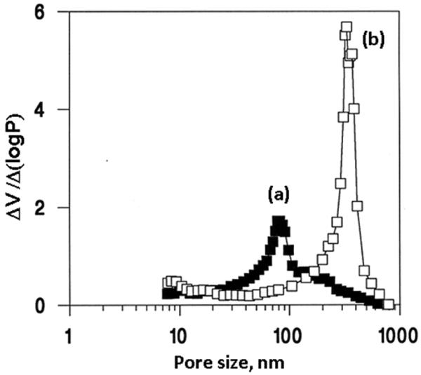
Mercury porosimetry differential pore size distribution profiles of the poly(glycidyl methacrylate-co-ethylene dimethacrylate) beads and monolith prepared via suspension (a) and bulk (b) polymerization at a temperature of 70 °C from a polymerization mixture comprising azobisisobutyronitrile(1% with respect to monomers), 24% glycidyl methacrylate, 16% ethylene dimethacrylate, cyclohexanol 48%, and dodecanol 12%. Reproduced from ref. [43] with permission.
3.1.1 Control of Porous Properties
Application of porous materials in chromatography relies on intimate contact with a surface that supports the interacting sites. In order to obtain a large surface area, a large number of smaller pores should be incorporated into the polymer. The most substantial contribution to the overall surface area comes from the micropores, with sizes smaller than 2 nm 1, followed by the mesopores ranging from 2 to 50 nm. Even large macropores and gigapores make only an insignificant contribution to the overall surface area. However, these pores are essential in monoliths to allow liquid to flow through the material at a reasonable pressure. This pressure, in turn, depends on the overall porous properties of the material. Therefore, the pore size distribution of the monolith should be adjusted properly already during their preparation to fit the desired application. Key variables such as temperature, composition of the pore-forming solvent mixture, and content of crosslinking monomer allow the tuning of the pore size within a broad range spanning at least two orders of magnitude from tens to thousands of nanometers.
3.1.1.1 Temperature
The polymerization temperature, through its effects on the kinetics of polymerization, is a particularly effective means of control, allowing the preparation of macroporous polymers with different pore size distributions from a single polymerization mixture. An example that will be discussed in section 6.1 and demonstrated in Fig. 21 clearly shows the sharp pore size distribution profile detected for monolith prepared at a temperature of 70 °C with a maximum close to 1000 nm. In contrast, a very broad pore size distribution curve spanning from 10 to 1000 nm with no distinct maximum is observed for monolith prepared from the same mixture at 130 °C.
Fig. 21.
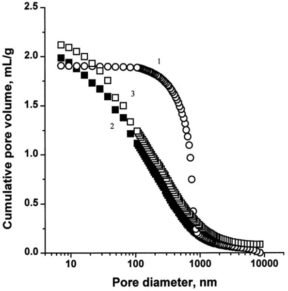
Integral pore size distribution profiles of porous polymer monoliths prepared by a typical polymerization at 70 °C (1) and in the presence (2) and the absence (3) of TEMPO at 130 °C. Conditions: polymerization mixture–styrene 20 wt%; divinylbenzene 20wt %; 1-dodecanol 60 wt%; benzoyl peroxide 0.5 wt % (with respect to monomers); TEMPO 1.2 molar excess with respect to benzoyl peroxide. Reproduced from ref. [47] with permission.
The effect of temperature can be readily explained in terms of the nucleation rates, and the shift in pore size distribution induced by changes in the polymerization temperature can be accounted for by the difference in the number of nuclei that result from these changes [45,46]. In contrast, changes in the thermodynamic quality of the solvent resulting from the increase in temperature seem to be not substantial. The temperature affects mostly the specific surface area that is typically related to the small pores. Because the monomers are thermodynamically better solvating agents for the polymer than the porogen, the precipitated insoluble gel-like nuclei swell with the monomers that are still present in the surrounding liquid. Following the nucleation step, the polymerization continues both within the separated phase of monomer swollen nuclei and in the remaining liquid polymerization mixture. If the polymerization temperature is low, the reaction rate is slow and transfer of a substantial part of monomers from solution in the nuclei can occur. Polymerization within the nuclei is kinetically preferred because the local concentration of the monomers is higher than in the surrounding solution. As the temperature increases, the number of polymer molecules that are formed in the solution after the original nucleation grows. These are captured by the growing nuclei and form larger clusters with less individualized texture. This results in a decrease in the surface area. At even higher temperature, the polymerization reaction is very fast and more growing chains are transformed into individual globules rather than being captured by the primary nuclei. These globules are small and, therefore, their surface is larger [46].
3.1.1.2. Porogens
The choice of pore-forming solvent or porogen is another tool that may be used for the control of porous properties without changing the chemical composition of the final polymer. Fig. 2 shows the massive effect of the content of thermodynamically poorer solvent or macroporogen dodecanol in the polymerization mixture on pore size distribution. In general, larger pores are obtained using more macroporogen due to an earlier onset of phase separation. The porogenic solvent controls the porous properties of the monolith through the solvation of the polymer chains in the reaction medium during the early stages of the polymerization [45,47].
Fig. 2.
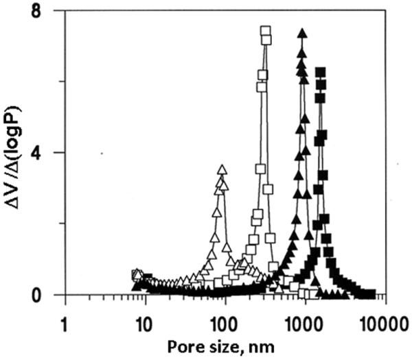
Mercury porosimetry differential pore size distribution curves of the poly(glycidyl methacrylate-co-ethylene dimethacrylate) monoliths prepared from mixtures containing 6 (triangles) and 12% dodecanol (squares) using polymerization at a temperature of 55 (closed points) and 70 °C (open points). Reproduced from ref. [43] with permission.
The choice of porogens for the preparation of porous polymer monoliths remains an art rather than science. This is why not that many porogens have been used and most often proven porogen mixtures are applied. For example, the initially used mixture of cyclohexanol and dodecanol was adopted from our previous work directed towards porous poly(glycidyl methacrylate-co-ethylene dimethacrylate) beads [48]. And yet, these porogens are used over and over again even today and not only by us [49-57]. Similarly, a mixture of toluene with higher alcohols remains popular for the preparation of monolith from styrene and divinylbenzene [45]. Santora et al. carried out experiments with single solvent porogens including tetrahydrofuran, acetonitrile, toluene, chlorobenzene, hexane, methanol, dimethylformamide, and methyl-t-butyl ether, and prepared series of poly(divinylbenzene), poly(styrene-co-divinylbenzene), poly(ethylene dimethacrylate), and poly(methyl methacrylate-co-ethylene dimethacrylate) monoliths [58]. Although some of these solvents afforded polymers with a surface area as large as 820 m2/g, it is unlikely that they would be permeable to flow since the pores were rather small.
Zhu et al. used another set of single porogens comprising cyclohexanol, 1-propanol, dodecanol, dimethylsulfoxide, and 1,4-butanediol for the preparation of monolithic poly(glycidyl methacrylate-co-ethylene dimethacrylate) columns [59]. Once again, none of these porogens enabled formation of monolith with the desired porous properties. In contrast, use of a binary porogens such as a mixture of 1,4-butanediol and dimethylsulfoxide led to monolithic capillaries with excellent permeability.
Toluene and its mixtures with higher alcohols are often used for the preparation of poly(styrene-co-divinylbenzene) monolith [60-63]. In contrast, Huber's group used a mixture of decanol and tetrahydrofuran as a porogen while focusing on the preparation of poly(styrene-co-divinylbenzene) monoliths [64-66]. Their capillary columns separated well oligo- and polynucleotides and nucleic acids as demonstrated in Fig. 3 [67]. The same mixture of porogens was also used for the preparation of poly(glycidyl methacrylate-co-divinylbenzene) columns [68].
Fig 3.
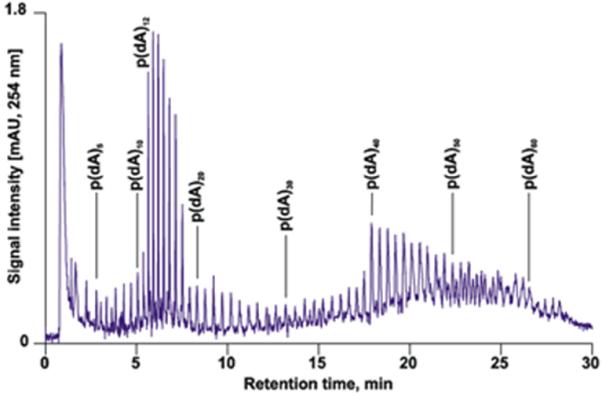
High-resolution of phosphorylated and non-phosphorylated oligonucleotides in a monolithic capillary column. Conditions: Poly(styrene-co-divinylbenzene) monolith, 60 × 0.2-mm i.d, gradient, 1-7 % acetonitrile in water in 5 min, 7-8% in 5 min, 8-9% in 6 min, 9-10.4% in 14 min in 100 mmol/L triethylammonium acetate, flow rate 2.1 μL/min, 50 °C. Reproduced from ref. [67] with permission
A new challenge arrived in the arena of porogens with the “reinvention” of capillary electrochromatography in the late 1990's [69]. The monolith had to contain both hydrophobic moieties providing the reversed phase retention and ionizable functionalities required for electroosmotic flow. In addition, the polymerization mixture had to be homogeneous to facilitate handling. We designed a unique porogenic system comprising water, 1,4-butanediol, and 1-propanol that dissolved hydrophobic alkyl methacrylate monomer, ethylene dimethacrylate 1 crosslinker, highly hydrophilic 2-acrylamido-2-methyl-1-propanesulfonic acid, as well as the azobisisobutyronitrile initiator and enabled to obtain monoliths with the desired porous structure [70-72]. Once again, this mixture remains quite popular even in the current literature [73-75].
Another family of porogens is represented by solutions of polymer in a solvent. In a very thorough study of effects of poly(ethylene glycol) (PEG) dissolved in 2-methoxyethanol and on the porous properties of copolymer of glycidyl methacrylate-cotrimethylolpropane trimethacrylate-co-triethylene glycol dimethacrylate) monoliths, Irgum's group found that the larger the molecular weight of PEG, the larger the pores [76]. They also monitored effect of numerous solvents used as a co-porogen on the porous properties. Novotny's group used a solution of poly(ethylene oxide) in N-methylformamide to prepare homogeneous polymerization mixture also consisting of acrylamide 9, methylene-bisacrylamide 9, acrylic acid, and alkyl acrylates and obtained columns for capillary electrochromatography [77]. Aqueous solution of poly(ethylene glycol) was later used as porogen for the preparation of monoliths from poly(ethylene glycol diacrylates) [78]. Li et al. described monolithic poly(ethylene glycol methyl ether acrylate-co-polyethylene glycol diacrylate) capillary columns prepared using poly(propylene glycol)-block-poly(ethylene glycol)-block-poly(propylene glycol) triblock copolymer and diethyl ether as porogen. These columns were tested for size exclusion chromatography [79]. A combination of high molecular mass polystyrene and chlorobenzene was used for the preparation of poly(glycerol dimethacrylate) monoliths with an interesting morphology shown in Fig. 4 [80]. This monolith contained certain amount of mesopores and was used for the separation of small molecules with an efficiency of up to 34 000 plates/m. Sinitsyna et al. tested a series of porogens including solutions of polystyrene in toluene-dodecanol mixture and poly(dimethylsiloxane) in hexane-dodecanol mixture for the preparation of poly(glycidyl methacrylate-co-ethylene dimethacrylate) monolithic layers. They found that the monolith prepared in the presence of polystyrene was best suited for the immobilization of antibodies and suitable for the fabrication of protein microarrays [81].
Fig. 4.
Morphology of poly(glycerol dimethacrylate) monolith prepared using solution of polystyrene with a molecular mass of 3 840 000 in chlorobenzene. Reproduced from ref. [80] with permission
Supercritical carbon dioxide is another contribution to the broad family of porogenic solvents [82-85]. This type of porogen pioneered by Cooper is attractive since it is nontoxic, non-flammable, and inexpensive. In addition, the properties of this “solvent” can be tuned by varying the pressure. Once the polymerization is completed, the porogen is simply evaporated with no need for washing and with no residual solvents in the monolith. Using ethylene dimethacrylate 1 and trimethylolpropane trimethacrylate 5 (Fig. 5) as monomers, a broad range of materials with typical macroporous structures and pore sizes in a range of 20-8000 nm were prepared and their porous properties characterized. This approach was later repeated by other authors [86]. Alternatively, they successfully used 1,1,1-2-tetrafluoroethane that can be liquefied at much lower pressure than CO2 [86,87]. However, none of these interesting approaches have yet been transferred to the chromatographic column technology.
Fig. 5.
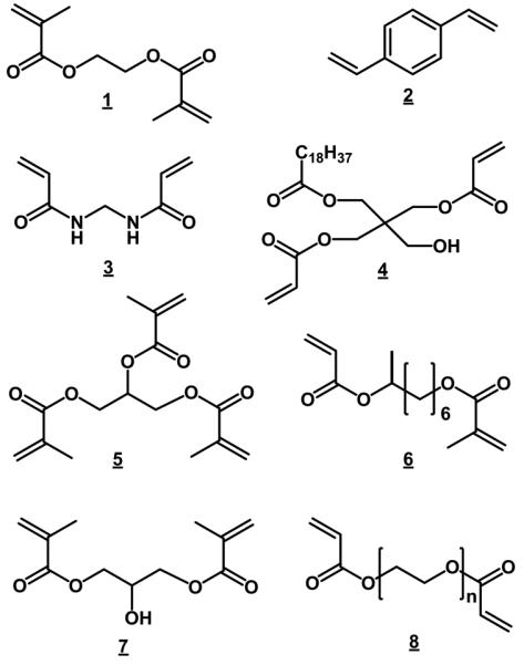
Examples of crosslinking monomers used for the preparation of porous polymer monoliths
3.1.1.3 Crosslinking monomer
In contrast to temperature and porogenic solvent that affect the porous properties of the resulting material but not its composition, variations in the monovinyl/divinyl monomer ratio not only induce the formation of different porous structures but also lead to materials with different compositions. A higher content of divinyl monomer directly translates into the formation of more highly cross-linked polymers in the early stages of the polymerization process and therefore lead to earlier phase separation. Although this is similar to the effect of poor solvent, the nuclei are more cross-linked and since this crosslinking negatively affects their swelling with the monomers, they remain relatively small in size. The pre-globules can still capture the nuclei generated during the later stages of polymerization, but true coalescence does not occur. Since the final macroporous structure that results consists of smaller globules, it also has smaller voids. Thus, this approach is useful for the preparation of monoliths with very large surface areas [45,58]. Experiments with various monomer mixtures containing increasing percentage of ethylene dimethacrylate and divinylbenzene, respectively, clearly documented the shift in the pore size distributions toward smaller pore sizes as the percentage of crosslinker was increased. These results imply that in this case the pore size distribution is controlled by the swelling of crosslinked nuclei. Because this approach to the control of the porous structure is accompanied by changes in polymer composition, it may not be suitable for the preparation of monoliths in which both the highest possible content of a functional monovinyl monomer and a large surface area are desirable [45].
The morphology of the monoliths is closely related to their porous properties, and is also a direct consequence of the quality of the porogenic solvent as well as the percentage of crosslinking monomer and the ratio between the monomer and porogen phases. The presence of interactive effects between these reaction conditions was verified using multivariate analysis [88].
Similar to the situation with porogens, the number of most often used crosslinkers is limited (Fig. 5). One of the reasons is commercial availability of these compounds. Ethylene dimethacrylate 1 is most often used in the acrylate/methacrylate family of monoliths, divinylbenzene 2 typically with styrenic monomers and methylenebisacrylamide 3 in aqueous systems [27]. This does not mean that other crosslinkers were not used. For example El Rassi's group introduced pentaerythritol diacrylate monostearate 4 that combines both crosslinking and hydrophobic functionalities in the preparation of monoliths for capillary electrochromatography, affinity chromatography and HPLC [52,89,90]. This monomer was later used by others [91,92]. Trimethylolpropane trimethacrylate 5 is another crosslinker often used for the preparation of monoliths [93-97].
An interesting study was published by Xu et al. [98]. They copolymerized several dimethacrylates differing in the length and branching of the connecting hydrocarbon chain with stearyl methacrylate in capillaries while keeping the molar ratio of both monomer and crosslinker constant. They observed the significant effect of the crosslinker chemistry on chromatographic performance in the separation of small molecules thanks to the changes in the volume of small pores. For example, a column containing copolymer of 2-methyl-1,8-octanediol dimethacrylate 6 exhibited a remarkable efficiency of 83 000 plates/m for unretained thiourea. However, the surface area measurement using nitrogen adsorption/desorption revealed only about 2 m2/g, a value that does not support the claimed effect of an increased volume of mesopores on column efficiency.
In pursuit of higher hydrophilicity to prevent non-specific interactions of a hydrophobic type, several hydrophilic acrylate and methacrylate-based crosslinkers such as 1,3-glycerol dimethacrylate 7 were also used. Li et al., applied poly(ethylene glycol) diacrylate 8 as crosslinker and prepared monolithic capillary columns for strong cation-exchange chromatography of peptides and proteins [99] and monoliths for size exclusion chromatography of proteins [79]. Kubo et al. used this crosslinker as the single monomer and studied the effect of polymerization conditions on the morphology of the monolithic polymer [78].
3.1.1.4 Polymerization time
We observed a significant effect of polymerization time on porous properties of poly(glycidyl methacrylate-co-ethylene dimethacrylate) monoliths already in one of our early publications [43]. For example, a monolith prepared by polymerization at a temperature of 55 °C exhibited a surface area of over 500 m2/g. Since the conversion was only 18%, most of the monomers remained unpolymerized and this initial monolith had a high pore volume of 3.8 mL/g. Although the conversion of monomers to polymer was close to quantitative after about 10 h, some additional structural changes still occurred if the system was kept longer at the polymerization temperature. However, no significant changes are observed at reaction times exceeding 22 h. Both surface area and pore volume were after this time significantly lower reaching 120 m2/g and 1.1 mL/g, respectively.
The control of porous properties via reaction time was recently adopted by Bonn's group [100]. They prepared monolithic poly(4-methylstyrene-co-1,2-(4-vinylphenyl) ethane) capillary columns using polymerization times varied from 30 min to 24 h. Once again, the surface area dropped from 76 to 23 m2/g and pore volume from 70 to 40%. Most interesting is the high column efficiency of 65 000 plates/m calculated from results of the isocratic separation of small aromatic molecules using a column polymerized for only 45 min at which time the conversion was 39%. Fig. 6 shows an excellent separation of phenol derivatives using this column. The separation gradually deteriorates with the increase in polymerization time and is completely unacceptable in column polymerized for 24 h. Although this less common approach to control of porous properties appears inspiring, the batch-to-batch repeatability needs to be demonstrated to make it even more convincing.
Fig. 6.
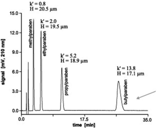
Separation of phenol derivatives using 80 × 0.2 mm I.D. monolithic poly(4-methylstyrene-co-1,2-(4-vinylphenyl)ethane) capillary column polymerized for 45 min. Conditions: column 80 × 0.2 mm I.D., mobile phase 25% acetonitrile in 0.1% aqueous trifluoroacetic acid, flow rate 4 μL/min, UV detection at 210 nm. Reproduced from ref. [100] with permission.
3.1.2 Surface chemistries
Obviously, the monolithic material may serve its purpose only if provided with surface chemistry that in turn depends on the desired application. For example, hydrophobic moieties are required for reversed phase chromatography, ionizable groups must be present for the separation in ion-exchange mode, reactive for affinity modes, and chiral functionalities are the prerequisite for enantioselective separations. Several methods have been developed and are now available for the preparation of polymer-based monolithic stationary phases with desired surface chemistry.
3.1.2.1 Preparation from functional monomers
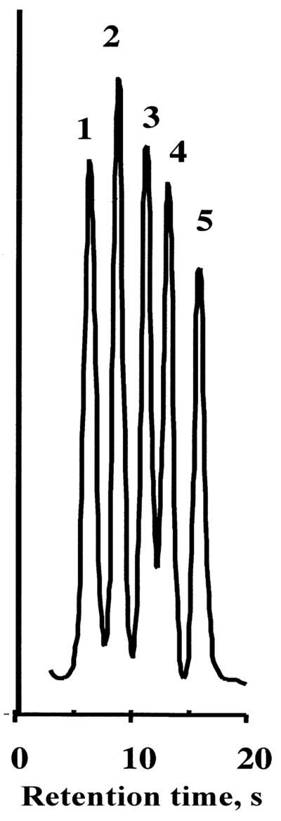
The number of monomers that may be used in the preparation of polymer monoliths is much larger than those used for classical suspension polymerization because there is only one phase in the mold. Therefore, almost any monomer, including water-soluble hydrophilic monomers, which are not suitable for standard polymerization in aqueous suspensions, may be used to form a monolith. This greatly increases the variety of surface chemistries that can be obtained directly. However, the polymerization conditions optimized for one system cannot be transferred immediately to another without further experimentation, and the use of new monomer mixtures always requires optimization of polymerization conditions in order to achieve sufficient permeability of the resulting monolith [101]. A few examples of monomers that have been used for the preparation of porous rigid monoliths are shown in the Fig. 7. The list of monomers includes a broad variety of chemistries varying from hydrophilic (acrylamide 9, 2-hydroxyethyl methacrylate 10), ionizable (2-acrylamido-2-methyl-1-propanesulfonic acid 11, (methacryloyloxy)ethyltrimethylammonium chloride 12, acrylic acid 13), reactive (glycidyl methacrylate 14, 2-vinyl-4,4-dimethylazlactone 15, chloromethyl styrene 16), protected (4-acetoxystyrene 17), hydrophobic (styrene 18, butyl methacrylate 19) to zwitterionic 20 functionalities, and also chiral monomers [88,101-107]. For example, directly polymerized poly(styrene-co-divinylbenzene) monoliths have proven to be an excellent stationary phase for the very fast separation of peptides and proteins shown in Fig.8 [108].
Fig.7.
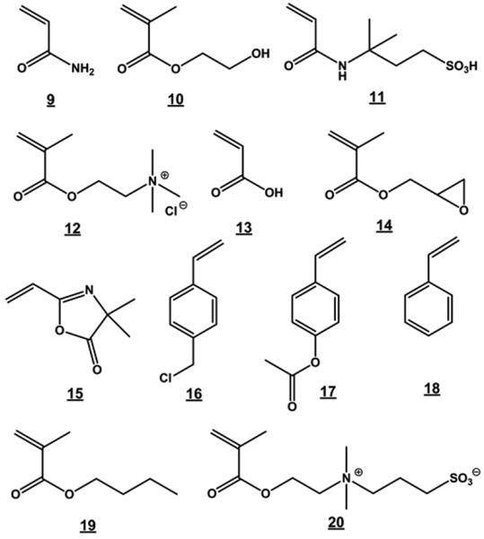
Examples of monomers used for the preparation of porous polymer monoliths.
Fig. 8.
Rapid reversed-phase separation of proteins at a flow-rate of 10 ml/min using 50×4.6 mm I.D. poly(styrene-divinylbenzene) monolithic column. Conditions: Mobile phase gradient: 42% to 90% acetonitrile in water with 0.15% trifluoroacetic acid in 0.35 min. Detection: UV 280 nm. Peaks: ribonuclease (1), cytochrome c (2), bovine serum albumin (3), carbonic anhydrase (4), chicken egg albumin (5).
3.1.2.2 Modification of reactive monoliths
Another option is the preparation of a monolith with reactive functionalities and its subsequent modification increases the number of available chemistries to afford stationary phases for a variety of separation modes. In this technique, each single reactive site affords one new functionality. Among others, glycidyl methacrylate-based monoliths have been widely used in these applications [109].
Typically, pores of a monolith prepared from monomers containing reactive group are filled with the reagent and allowed to react. Once the reaction is completed, the monolith is flushed with a solvent to remove all unreacted components and is ready for application. For example, Fig. 9 of shows the reaction of glycidyl methacrylate-based monolith with diethylamine, which leads to a widely used anion-exchanger [38]. The reaction of poly(chloromethylstyrene-co-divinylbenzene) with ethylenediamine and then with γ-gluconolactone completely switches the surface polarity from hydrophobic to hydrophilic [110]. The major benefit of this modification is simplicity of the single step polymerization process that was previously optimized.
Fig. 9.
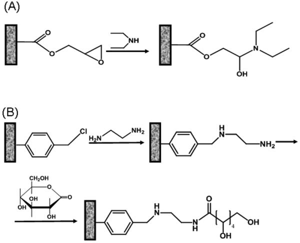
Examples of modification of typical porous polymer monoliths containing glycidyl methacrylate (A) and chloromethylstyrene (B) units.
3.1.2.3 Grafting
The preparation of functionalized monoliths by copolymerization of functional monovinyl and divinyl monomers requires re-optimization of the polymerization conditions for each new set of functional monomers and crosslinkers in order to obtain monoliths with the desired properties. Since the functional monomer constitutes both the bulk and the active surface of the monolith, a substantial percentage of the functional units remains buried within the highly crosslinked polymer matrix and is inaccessible for the desired interactions. A better utilization of a rare functional monomer might involve its grafting polymerization on pore surface of a “generic” monolith. Using the simple modification process shown in section 3.1.2.2, only a single functionality is obtained by reacting each functional site of the surface. In contrast, the attachment of chains of a functional polymer to the reactive site at the surface of the pores would provide multiple functionalities emanating from each individual surface site, and thus dramatically increase the density of group located at the pore surface. Such materials, which possess higher binding capacities, are attractive for use in chromatography, ion-exchange, and adsorption. Müller has demonstrated that the cerium (IV) initiated grafting of polymer chains onto the internal surface of porous beads afforded excellent separation media for biopolymers [111]. We used similar reaction to graft poly(2-acrylamido-2-methyl-1-propanesulfonic acid) 11 onto the internal surface of hydrolyzed poly(glycidyl methacrylate-co-ethylene dimethacrylate) monoliths [112]. Unfortunately, this grafting reaction carried out in concentrated nictric acid is sensitive to oxygen and works best with primary alcohols while diols like those obtained via hydrolysis of epoxide are less suitable.
Extending our original work concerned with functionalization of channels in microfluidic chips fabricated from thermoplasts using photografting [113], we have developed procedure enabling functionalization of monoliths [114]. We adopted the mechanism that was first used by Rånby [115] for photografting onto polymer films applying aromatic ketones such as benzophenone as photoactive component. According to Rånby's mechanism, excitation of the photoinitiator by UV light at 200-300 nm ultimately leads to hydrogen abstraction and formation of a free radical on the polymer substrate. This energy rich radical then initiates propagation reaction leading to grafting from the surface. The counterpart semipinacol radical formed simultaneously from the initiator does not have sufficient energy to initiate polymerization in solution to any significant extent and is mostly quenched by combination leading to its dimerization or termination of the growing polymer chains. Since the growing polymer chains grafted to the surface also contain abstractible hydrogen atoms, these new chains also serve as loci from which new chains can grow, ultimately leading to a branched polymer architecture. This technique became a topic of several studies [50,116-122].
Photografting also enables control of porous properties of the monolith independently from management of its surface chemistry. In other words, this process makes possible to perfect porous structure of the “generic” monolithic first and then prepare a variety of functionalized monoliths from it via the photografting step. This is useful while studying effects of surface chemistry alone on separation since the monoliths possess the same porous structure. This process also has a number of other advantages. It allows preparation of monoliths that would be difficult to obtain using single step copolymerization. For example, it is difficult to create a homogeneous polymerization mixture from monomers differing largely in polarity such as hydrophobic alkyl methacrylate and hydrophilic 2-acrylamido-2-methyl-1-propanesulfonic acid [123]. It is also known that a significant portion of functional monomers may be buried within the crosslinked polymer matrix and inaccessible for interactions. Ionizable functionalities tend to solvate in aqueous environment which leads to swelling of the matrix and change in its porous properties and permeability.
In addition to the single-step photografting described in the previous paragraph, we have also investigated a sequential two-step photografting shown in Fig. 10 [122]. In the first step, initiator moieties are formed at the pore surface by UV irradiation of a polymer monolith that is in contact with the benzophenone solution. This compound abstracts hydrogen from the polymer surface and creates a free radical. However, in the absence of monomers, the surface radical and the newly formed semipinacol radical combine to form a surface-bound initiator. The second step of graft polymerization is then carried out with a solution containing only monomer. UV irradiation liberates the immobilized latent free radicals located on the polymer that then initiate graft polymerization from the surface. Besides reducing the formation of non-grafted polymer in solution (in comparison to the single-step techniques where both initiator and monomer are present in solution), the sequential approach provides additional control over grafting because the overall process including hydrogen abstraction and grafting polymerization is decoupled into two separate steps. This decoupling also enlarges the spectrum of solvents that can be used since those suitable for benzophenone may not be ideal for the dissolution of monomers. Thus, this two-step sequential photografting technique allows for a greater degree of control over the grafting process and was also used for the fabrication of monolith resistant to adsorption of proteins [122].
Fig. 10.

Scheme of the two-step sequential photografting procedure. Reproduced from ref. [122] with permission.
The photoinitiated process enables simultaneous grafting of more than a single monomer. Eeltink et al. co-grafted (2-methacryloyloxy)ethyl-trimethylamonium chloride and butyl acrylate to control electroosmotic flow in CEC columns [50]. Photografting can also proceed in sequential mode with a plurality of monomers grafted over each other. This approach was first used for the preparation of CEC columns with shielded ionizable chemistries [121]. In order to avoid interaction of ionized peptides and proteins with sulfonic acid functionalities, a layer of poly(2-acrylamido-2-methyl-1-propanesulfonic acid) was photografted first followed by grafting butyl methacrylate on the top of the first layer. Similar method was used to prepare reactive supports with enhanced biocompatibility from poly(glycidyl methacrylate-co-ethylene dimethacrylate) monoliths. After hydrolysis of the epoxide groups to a diol, poly(ethylene glycol) methacrylate was grafted within the pores and in the next step the pore surface was activated by photografting 1-vinyl-4,4-dimethylazlactone 15. This monolith was then used for the fabrication of highly active immobilized enzyme microreactors [116,117]. Similarly, this grafted support also enabled the preparation of ion exchange columns exhibiting high loading capacity [124]
The downturn of photografting is the need of UV transparent “molds” and monomers. Thus, typical polyimide coated capillaries and aromatic monomers such as styrene cannot be used. Also due to UV adsorption of the polymer matrix itself, the photografting is effective only for monoliths which one dimension (typically thickness) is short.
Grafting can also provide the monolithic polymers with rather unexpected properties. For example, a two step grafting procedure which involves the vinylization of the pore surface by reaction of the epoxide moiety with allyl amine, and a subsequent in situ radical polymerization of N-isopropylacrylamide (NIPAAm) initiated within these pores by azobisisobutyronitrile leads to a composite that changes its properties in response to external temperature [125]. Monolithic column based on poly(chloromethylstyrene-codivinylbenzene) monolith grafted with poly(N-isopropylacrylamide) via atom transfer radical polymerization (ATRP) was recently used for the separation of proteins in hydrophobic interaction mode which performance was controlled by temperature [126].
The living character of some polymerization techniques used for the preparation of monoliths and described later in section 6 of this review also enables grafting of functional monomers and manipulation of the pore surface chemistry.
3.1.2.4 Attachment of nanoparticles
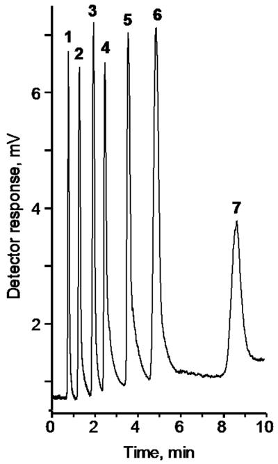
Yet another option for the functionalization of monoliths is attachment of nanoparticles to the pore surface. A few decades ago, Dionex introduced very successful column packings for ion chromatography that consisted of non-porous micrometer sized poly(styrene-co-divinylbenzene) beads sulfonated on their outer surface that were covered with anionic latex nanoparticles. Inspired by this approach, we prepared a monolith by copolymerization of butyl methacrylate, ethylene dimethacrylate, and 2-acrylamido-2-methyl-1-propanesulfonic acid [127]. Then, a dispersion of 60 nm latex particles bearing quaternary amine functionalities was pumped through the capillary. SEM micrographs clearly revealed nanoparticles attached to the pore surface. This monolith then enabled a fast separation of carbohydrates such as that shown in Fig. 11 Simultaneously, Haddad's group used a similar process that afforded latex-coated polymer monolith and used it for the separation of anions in capillary electrochromatography and micro HPLC mode, respectively [128,129]. Although both these approaches afforded the desired separations, the surface coating with latex particles was not complete thus limiting the loading capacity. This problem was solved by Hilder et al. recently who optimized the surface modification conditions and achieved a homogeneous coverage of pore surface with latex particles [130].
Fig. 11.
Separation of a mixture of carbohydrates by anion-exchange chromatography using an optimized latex-coated polymeric monolithic capillary column. Conditions: Column size 10 cm ×250 μm i.d, pore size 0.97 μm. Flow rate 13 μL/min Mobile phase aqueous ammonium hydroxide 64 mmol/L (pH 12.8). Peaks: D(+)galactose (1), D(+)glucose (2), D(+)xylose (3), D(+)mannose (4), maltose (5), D(−)fructose (6), sucrose (7). Reproduced from ref. [127] with permission.
We have recently extended this early approach to immobilize gold nanoparticles on the pore surface of polymer monoliths [131]. The procedure is simple: First, epoxy groups of poly(glycidyl methacrylate-co-ethylene dimethacrylate) monolith react with cysteamine to afford thiol functionalities that are known to be well suited for the interaction with gold nanoparticles. Then, the nanoparticles are formed in situ via reaction of chloroauric acid with trisodium citrate at elevated temperature. Alternatively, preformed dispersion of gold nanoparticles is pumped through the functionalized monolith. The nanoparticles adhere strongly to the pore surface and contribute significantly to the separation performance. For example, no separation of peptides could be observed using the poly(glycidyl methacrylate-co-ethylene dimethacrylate) monolith and only a poor separation is achieved with its cysteamine modified counterpart. In contrast, a good separation of peptides was obtained with the column containing the gold nanoparticles. This column can also be readily used for the selective “fishing out” of peptides containing thiol group thus enabling simplification of complex peptide mixtures such as protein digests.
3.2 Photoinitiated polymerization
Photoinitiation emerged in the arena of monoliths in 1997 [88]. A systematic study of the preparation of monoliths from glycidyl methacrylate and trimethylolpropane trimethacrylate in a 2.4 mm I.D. quartz tube using multivariate evaluation clearly demonstrated the potential of photopolymerization that was found significantly faster than the thermally initiated process. This new technique did not initially find too much resonance since the thermally initiated polymerization was a standard and was well suited for the preparation of monolithic structures that completely filled the entire volume of a hermetically closed mold such as a column for HPLC. However, completely filled devices might not always be desired. For example, the preparation of monoliths in microfluidic chips requires their formation in a specific location while other parts must remain open. Therefore, a light initiated polymerization process is very well suited to achieve monolith formation within a specified space. Using a mask, the polymerization may be restricted to the irradiated areas beneath the open parts of the mask while monomers do not convert to polymer in those areas that are not irradiated. The same technology is widely used for microelectronic patterning.
The concept of photopolymerization is simple. A mixture similar to that typically used for the thermally initiated process is introduced in the mold and irradiated with UV light to initiate the polymerization. Compared to thermally initiated polymerization, photopolymerization is significantly faster even at room temperature and can be completed in minutes rather than in hours. Since it runs at room temperature, a number of less common porogens including those with low boiling point such a methanol, ethanol, chloroform, ethyl acetate, and hexane can also be used [132]. The only limitations of this technique are in the use of UV transparent molds with a small size in one dimension and UV transparent monomers. The former is readily achieved using Teflon coated capillaries and glass chips, the latter excludes aromatic monomers such as styrene and divinylbenzene but leaves available a plethora of other monomers and crosslinkers including a large number of various acrylates and methacrylates such as glycidyl methacrylate, butyl acrylate and methacrylate, sulfobetaines, butanediol diacrylate, and ethylene dimethacrylate shown in Fig. 5 and 8. For example, Daley and Oleshuk developed monolithic columns from fluorinated monomers 1H,1H-heptafluorobutyl acrylate and 2,2,3,3-tetrafluoro-1,4-butyl diacrylate and used them for the separations of fluorous tagged molecules using aqueous acetonitrile as the mobile phase [133]. Lee's group copolymerized 2-acrylamido-2-methyl-1-propanesulfonic acid, 2-(diethylamino)ethyl methacrylate and 2-(acryloyloxy)ethyl trimethylammonium chloride with poly(triethylene glycol diacrylate) as the crosslinker [134]. The latter impaired the monoliths with enhanced hydrophilicity and reduced undesired hydrophobic interaction of proteins with the monolith during the ion exchange chromatography. Recent introduction of the UV light emitting diodes represents a new twist in the field of photopolymerized monoliths [135,136].
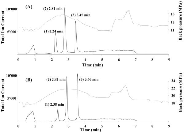
An important part of the polymerization mixture is the photoinitiator. Azobisisobutyronitrile is quite popular. It decomposes while irradiated at 365 nm to afford free radicals [132,137-142]. Since this initiator can also be used for the thermally initiated polymerization, comparative studies of both these approaches have been carried out [143,144]. They found only small differences in chromatographic performance of both types of monolithic capillary columns as demonstrated with separations of proteins shown in Fig. 12. However, the photoinitiated monoliths exhibited about twice as high back pressure thus indicating a difference in the porous structure. Another initiators specifically designed for photopolymerization are aromatic ketones such as 2-methoxy-2-phenylacetophenone (benzoin methyl ether) [88,102,145,146] and 2,2-dimethyl-2-phenylacetophenone [99,134,147-150] that work at different wavelengths.
Fig. 12.
Chromatographic separation of three model proteins using monolithic poly(butyl methacrylate-co-ethylene dimethacrylate) capillary column prepared by thermally (A) and photochemically (B) initiated polymerization. Conditions: column 20 cm × 100 μm I.D.; mobile phase A 2% formic acid in 98:2 water:acetonitrile mixture, mobile phase B 2% formic acid in acetonitrile; gradient from 100% A to 50% B in A in 4 min; flow rate 4 μL/min. Peaks: (1) ribonuclease A (2 pmol), (2) cytochrome c (1 pmol), and (3) myoglobin (0.3 pmol). Dashed line represents the overall back pressure in the system. Reproduced from ref. [143] with permission.
3.3 Radiation polymerization
3.3.1 Use of γ-rays
Polymerizations initiated using high energy radiation such as γ-rays or electron beam belong to the group of “exotic” approaches to monoliths. The major advantages of this method are no need for an initiator and thus absence of any functional groups at the chain ends, polymerizations can be carried out at any temperature, and in almost any container including stainless steel tubes. A certain drawback is the limited access to the source of the γ-rays for majority of scientists and significant safety requirements while working with the radiation. Although the ionizing radiation also creates ions that may initiate the polymerization reaction, it creates much larger number of free radicals. Therefore the typical reaction mechanism is free radical polymerization. Since the radicals can be formed from all components of the polymerization mixture, the organic solvents used as porogen may play a significant role. Keeping a constant temperature during this type of polymerization is a challenge since the polymerization itself is an exothermic reaction and a part of the radiation is adsorbed and converted to heat.
Interestingly, an early report describing preparation of monolithic hydrogel from hydrophilic acrylates and methacrylates in a 18 mm I.D. glass tube using γ-rays from 60Co source has been published already in 1989 [151]. Similar to hydrogel monolith prepared by Kubin et al. earlier [30], these monoliths were not very permeable for liquids and several hours were needed to flow through mere 1 mL water.
Useful monoliths were prepared much later. Grasselli et al. used 60Co source to polymerize a mixture of diethylene glycol dimethacrylate and glycidyl methacrylate dissolved in variety of solvents including methanol, ethanol, tert-butanol, acetone, and ethyl acetate, respectively, placed in a 4 mm I.D. Teflon tube [152]. A dose exceeding 15 kGy was needed to achieve 100% conversion of monomers to polymer. Fig. 13 shows effect of the porogenic solvents on the porous structure. Permeability of the monoliths depended on the percentage of monomers in the mixture since monoliths prepared from more dilute monomer solutions exhibit higher porosity. An increase in the proportion of glycidyl methacrylate led to reduction in permeability. Also, more permeable monoliths were formed at higher polymerization temperature. A detailed study confirmed these findings [153] that contrast those observed for typical thermally initiated polymerizations [45,154].
Fig. 13.
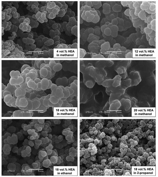
SEM micrographs of poly(2-hydroxyethyl acrylate-co-diethylene glycol dimethacrylate) monoliths prepared in presence of different porogenic solvents. Irradiation temperature 25 °C, dose rate of 16 kGy/h, total dose of 30 kGy. Reproduced from ref. [155] with permission.
The γ-rays initiated polymerization process affords monolith with pores sized at 3-5 μm with surface areas around 1 m2/g. Use of these monolithic columns for the isocratic separation of amino acids with water as the mobile phase was less successful. Yet, it concluded that the separation mechanism was combination of size exclusion, gel sieving, and hydrophobic interactions [155].
Using a similar approach, Viziolli at al. filled fused silica capillaries with a mixture of diethylene glycol dimethacrylate and glycidyl methacrylate dissolved in methanol and irradiated them with γ-rays at room temperature for 5 h at a dose rate of 5 kGy/h [156]. After reacting the monolith with iminodiacetic acid and loading with copper ions, the capillary was used for separation of peptides in IMAC mode. They also attached iron protoporphyrin IX to the monolith and used it for preconcentration of peptides [157].
3.3.2 Initiation using electron beam
Electron beam is applied as a high energy alternative to γ-rays to initiate polymerization. For example, Chuda et al. used electron beam originating from 2.2 MeV Van de Graaff accelerator operated at a high dose rate of 0.68 kGy/s (2.448 MGy/h) to prepare poly(2-hydroxyethyl methacrylate-co-ethylene dimethacrylate) monolith in 1 mm I.D. capillaries [158]. The permeability to flow was a function of a dose as shown in Fig. 14. Monolithic column prepared at a high dose was less permeable. This result is in accord with observations of effects of polymerization kinetics of typical free radical polymerization on the porous structure [154].
Fig. 14.
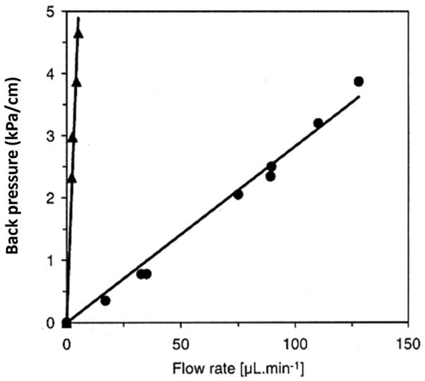
Back pressure per unit length of a 1mm I.D. monolithic capillary as a function of methanol flow rate for poly(2-hydroxyethyl methacrylate-co-ethylene dimethacrylate) monoliths polymerized using electron beam at a dose of 50 (●) and 100 kGy (▲) Reproduced from ref. [158] with permission.
More thorough studies on the preparation of porous polymer monoliths employing a 10 MeV linear accelerator are carried out in Leipzig [159-164]. Buchmeiser's group prepared poly(ethyl methacrylate-co-trimethylolpropane trimethacrylate) monoliths in 150 ×4.6 mm I.D. stainless steel column and 100×3 mm I.D. glass tubes [162]. The total dose of 22 kGy needed to achieve 100% conversion was applied in increments of ca. 3 kGy over a period of 15 min in order to keep the temperature in desired limits. The pore size varied around 1 μm and these monoliths enabled fast separations. Fig. 15 shows the separation of five proteins achieved in less than 2 min. Other mixtures such as dansyl derivatives of amino acids were also separated. The column performance compared favorably to a commercial silica-based C18 monolith [159] and polymer-based monolith obtained via ring-opening metathesis polymerization [163].
Fig. 15.
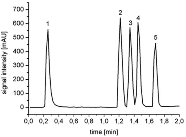
Separation of lysozyme (1), ribonuclease A (2), insulin (3), cytochrome c (4), and albumin (5) using poly(ethyl methacrylate-co-trimethylolpropane trimethacrylate) monolith prepared using electron beam initiated polymerization. Glass column 100×3 mm i.d.; mobile phase A: 95% water + 5% acetonitrile + 0.1% TFA; mobile phase B: 20% water + 80% acetonitrile + 0.1% TFA; linear gradient, 10-90% B in 2 min; flow rate, 3 mL/min; UV detection at 200 nm. Reproduced from ref. [162] with permission.
Scale up to 300×20 mm I.D. stainless steel column while increasing the dose to 34 kGy demonstrated the potential of this polymerization technique for facile single step preparation of large volume monolithic columns [162]. This approach was also down scaled and used for the preparation of 15 cm long 100 and 200 μm I.D. capillary columns with a very good permeability [164]. Detailed measurements confirmed very good reproducibility of the polymerization process and applicability for the separation of protein mixtures. However, the low polarity of the columns did not allow separation of peptides. Therefore, more hydrophobic monomers, lauryl methacrylate and ethylene dimethacrylate were also used for the preparation of monoliths [164]. Indeed, both smaller size of the microglobules and higher hydrophobicity of the chemistry led to a significant improvement in the chromatographic performance.
4 Polymerized high internal phase emulsions
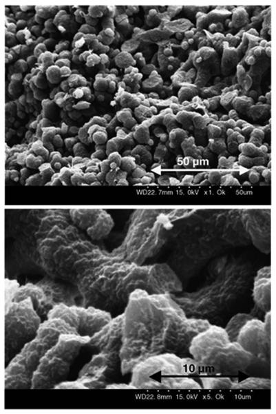
A new class of porous polymers called polymerized high internal emulsions or polyHIPE was invented in Unilever Research [165]. However, Small and Sherrington were the first to described these materials in detail [166,167]. They are prepared by emulsifying up to 90% water containing free radical initiator, typically potassium peroxodisulfate, and calcium chloride in 10% of an oil phase comprising monomers such as styrene and divinylbenzene, as well as a surfactant. Upon intensive stirring, this mixture forms a creamy white, rigid mass. This process is not too dissimilar from making a mayonnaise. It is then filled in a mold and polymerized at an increased temperature forming a monolith which porous structure is shown in Fig. 16. This highly porous structure consists of interconnected spherical voids, which are negative images of the originally present emulsified water droplets, connected with their neighbors through “windows” in the walls. The surface area of materials prepared from styrene containing small percentage of divinylbenzene is very low, typically less than 5 m2/g. An increase in divinylbenzene percentage to 20% affords polymer with more than 30 m2/g. However, an addition of a porogen such as toluene and a further increase in percentage of crosslinker yields polyHIPE with a surface area as large as 350 m2/g due to creation of mesopores in the polymer walls [168]. PolyHIPE with a very high surface area of 543 m2/g were then prepared from a mixture of pure high grade divinylbenzene (80% purity) with 2-chloroethylbenzene (porogens) [169].
Fig. 16.
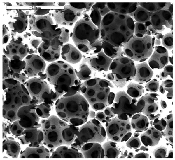
Scanning electron micrograph of a typical polyHIPE polymer. Reproduced from ref. [168] with permission.
A noteworthy feature of this technique is that the polymerization mixture contains a rather small percentage of monomers and their polymerization liberates limited amount of heat that then dissipates easily. Therefore, large monolith can also be made. For example, Cameron et al. prepared poly(styrene-co-divinylbenzene) polyHIPE monoliths in 14 × 4.5 cm I.D. mold and demonstrated their functionalization via electrophilic aromatic substitution reaction providing sulfonated, nitrated and brominated derivatives [170]. Polymerization of reactive monomers is an alternative approach to functionalized polyHIPE. Thus, chloromethylstyrene was polymerized in combination with styrene, divinylbenzene, in presence of chlorobenzene porogen to afford monolithic polyHIPE structure with a surface area of 223 m2/g measured using inverse size exclusion chromatography [171]. In a different study, polyHIPE was prepared from glycidyl methacrylate and ethylene dimethacrylate in a 50 × 4.2 mm I.D. stainless steel column. Thanks to the large pore size of 5.7 μm, the back pressure in the column was less than 1 MPa even at a flow velocity of 1 cm/s [172]. Use of several models correlating hydrodynamic properties of this monolith with their morphological structure enabled prediction of back pressure that reasonably matched the experimental value [173]. The poly(glycidyl methacrylate-co-ethylene dimethacrylate) polyHIPE monolith with epoxide functionalities was converted to anion exchanger via reaction with diethylamine and enabled a fast separation of proteins shown in Fig. 17 [172].
Fig. 17.
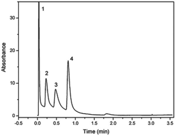
Fast anion exchange separation of lysozyme l (1), bovine serum albumin (2), ovalbumin (3), and pepsin (4) using a monolithic polyHIPE column with 2-hydroxy-3-(diethylamino)-propyl functionalities. Conditions: mobile phase: buffer A 10 mmol/L TrisHCl buffer, pH 7.6; buffer B 1 mol/L NaCl in A; gradient time 45 s; flow rate 6 mL/min; UV detection at 280 nm. Reproduced from ref. [172] with permission.
Recently, polyHIPE with a surface area of almost 400 m2/g were prepared from 80-20% glycidyl methacrylate-divinylbenzene mixtures. Interestingly, epoxy groups located in the large pores were hydrolyzed during the preparation while those located in mesopores smaller than about 6 nm remained intact [174].
A different approach to stabilizing polyHIPE was developed by Colver and Bon [175] who used an old Pickering concept [176]. Instead of using a typical low molecular weight surfactant for stabilization of the water-in-oil emulsions, they used poly(methyl methacrylate-co-divinylbenzene) nanoparticles. Chemistry of these colloids is controlled by composition of the polymerization mixture used for their preparation. They then formed monoliths from different monomers such as divinylbenzene, butyl methacrylate, and lauryl methacrylate. Using mixed or stacked emuslions stabilized with nanoparticles having different surface chemistry enabled spatial “patterning” of functionality in the resulting monolithic structure.
5 Cryogels
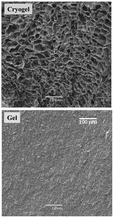
Although monolith from hydrogel was the first to be prepared [30], they never enjoyed an applications. Recently, Mattiasson's group in Lund developed a cryotropic gelation technique that affords spongy hydrophilic monolithic materials called cryogels featuring very large pores [177]. General scheme of the formation of a cryogel is shown in Fig. 18. They define their technique as follows: “Cryotropic gelation (or cryostructuration) is a specific type of gel formation that takes place as a result of cryogenic treatment of the systems potentially capable of gelation. The essential feature of the cryogelation is mandatory crystallization of the solvent …. The cryogels are synthesized in semi-frozen aqueous media where ice crystals act as porogen and template the continuous interconnected pores after melting” [177]. This definition accommodates two methods leading to the monoliths: (i) crosslinking of polymers such as polyvinylalcohol dissolved in water [178-180] and (ii) polymerization of monomers dissolved in water. In both cases the solution must be frozen prior to the reaction. Using the latter, a vast variety of cryogels has been prepared from monomers including 2-hydroxyethyl methacrylate [177], acrylamide [181-185], dimethylacrylamide [186], N-isopropylacrylamide [187,188], and N-vinylcaprolactam [189]. Crosslinkers such as methylenebisacrylamide and poly(ethylene glycol) diacrylate are used in the polymerization mixture to reinforce the macroporous structure and prevent dissolution of the monolith in the aqueous mobile phases during their application. Polymerization itself is typically initiated with a water soluble redox system including ammonium peroxodisulfate and N,N,N′,N′-tetramethylethylenediamine. UV initiated polymerization has also been demonstrated [189]. The polymerization mixture is prepared by dissolving all components in water, this mixture filled in a mold such as the column tube and rapidly cooled to a subzero temperature at which the polymerization is carried out for up to 24 h. Fig. 19 shows SEM micrographs of structures prepared from an identical mixture via polymerization at −20 and +20 °C. The difference is striking. While structure of material prepared at room temperature is virtually featureless, cryogel exhibits large interconnected pores separated by solid polymer walls.
Fig. 18.
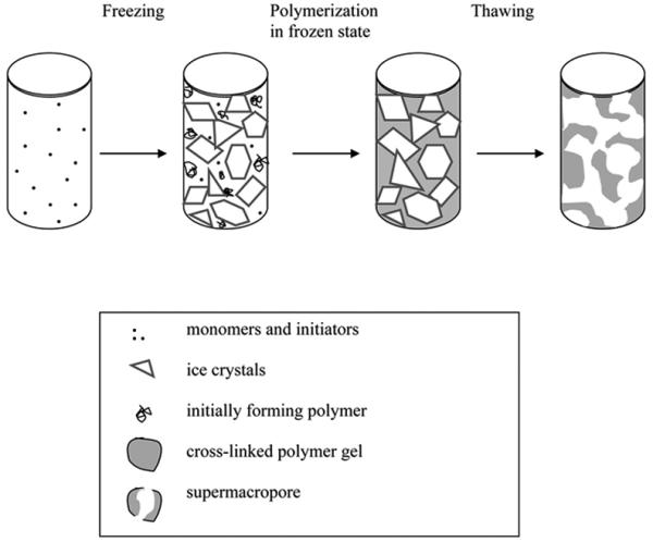
Scheme of formation of cryogels. Reproduced from ref.[185] with permission.
Fig. 19.
SEM of the dextran-based cryogel prepared at −20 °C and conventional dextran gel prepared at room temperature. Reproduced from ref. [177] with permission.
The creation of the porous structure relies on the phase separation during freezing with one phase being frozen crystals of water and another non-frozen liquid microphase. During the cooling, the water crystals grow to a point at which they form a continuous frozen framework, the porogenic structure. The frozen aqueous phase is interspersed with the continuous monomer rich phase which is liquid. Monomers in this phase polymerize thus preserving the bicontinuous structure and forming the pore walls. After completion of the polymerization reaction, the system is brought to the ambient temperature, water within pores thaws, and can be easily replaced with a mobile phase. This description of mechanism also indicates the major variables affecting the porous structure [190]. The first one is the temperature at which polymerization is carried out and the speed at which it is reached. Polymerization at too low temperatures leads to monoliths with smaller pores and reduced permeability to flow. However, polymerizing at a temperature that is not low enough, a supercooled state may persist and the desired structure is not formed [190]. The percentage of monomers in the aqueous solution also affects the porous properties. The more monomers in the mixture, the thicker the walls, and the smaller the pores. As a result, the monoliths prepared from mixture with high percentage of monomers are more mechanically stable but their hydrodynamic properties are less advantageous [181]. An increase in content of initiator in the polymerization mixture leads to the formation of more rigid structures. One component of the initiating system is an inorganic salt, ammonium peroxydisulfate, which also affects the freezing properties of the aqueous solution. Similar effect can also be expected from addition of organic co-solvents such as 1,4-dioxane or formamide [190].
Thanks to the very large pores in the 5-100 μm range and high porosity that may reach up to 90%, the hydrodynamic properties of cryogel monoliths are excellent. Since the back pressure in the system is typically low, the applicable flow rates can be high, yet compression of the structure is not a problem. The structural characteristics are most often assessed from SEM micrographs and flow properties [181,185,190].
The surface chemistry of typical cryogels is not very rich and is defined by the monomers used for their preparation. Therefore, a variety of grafting procedures have been developed that provide the cryogel monoliths with functionalities desired for a specific application. For example, potassium diperiodatocuprate was used to initiate grafting of monomers such as acrylic acid, 2-hydroxyethyl methacrylate, N-isopropylacrylamide, [2-(methacryloyloxy)ethyl]trimethylammonium chloride, 2-acrylamido-2-methyl-1-propane sulfonic acid, N,N-dimethylacrylamide, and N,N-dimethylaminoethyl methacrylate from pore surface of a polyacrylamide monolith with a high yield and afforded ion exchange, thermally responsive, and interactive columns [183,191-193].
The extremely large pores make these materials excel in the separations of solutes in the presence of particles and for isolation of biological particles such as microbial and mammalian cells [177,185,194]. Bioaffinity chromatography using cryogel monolith with immobilized concanavalin A [195] and Ni(II) ions [196] were also demonstrated. However, the binding capacity of these monoliths is inferior to those found for rigid monoliths [196]. The small surface area also makes cryogel monolith less suited for the separations of smaller entities such as proteins in adsorption modes. These monoliths are also useful as three dimensional scaffolds for growing cell cultures [177].
An interesting novelty somewhat related to cryogels is formation of monoliths from a mixture of soft polymer latex particles and silica nanoparticles in water that is frozen. The freezing separates again the mixture in two phases – ice crystals and solidified particles. A typical porous structure is then formed after sublimation of water in freeze drying process [197]
6 Living polymerizations
Standard porous polymer monoliths feature large through pores between aggregated microglobules. However, mesopores are most often completely missing. As a rule, these monoliths exhibit rather small surface areas typically less than 10-30 m2/g. This makes them well suited for the separations of large molecules in gradient elution mode but they fail to efficiently separate small molecules under isocratic conditions for which a large surface area is necessary. This fact has led to exploration of less common techniques such as living polymerization in pursuit of better control of porous properties of polymer monoliths.
Polymerization that may restart chain growth after addition of a new portion of monomers is called living. The living nature is typically due to missing termination and chain transfer reactions. This type of polymerizations is also characterized by a fast and quantitative reaction of an initiator or catalyst with monomers thus creating all potentially growing polymer chains at the same time. This gives the chance to all growing chains to grow at the same speed. As a result, polymers with similar chain length are formed. In the case of monolith, this should mean that the nucleation and phase separation could be better controlled, and more homogeneous structure could be formed.
6.1 Nitroxide mediated
Georges et al. were the first to report the living character of free radical polymerization in presence of 2,2,6,6-tetramethyl-1-piperidyloxy (TEMPO) shown in Fig. 20 [198]. This compound combines reversibly with growing polymer chain radicals thus forming a dormant species that dissociate again thus enabling further growth of the polymer chain. This relatively slow alternating activation-deactivation of the growing end controls the propagation rate that is then equal for all chains. As a result, all chains have then a similar length. The initial works concerning high-temperature styrene polymerization generated much interest in nitroxide chemistry and the living radical polymerizations have received a great deal of attention during last two decades due to their potential for combining the chemical robustness of free radical polymerizations with the high level of control over polymer composition and architecture characteristic of traditional ionic living polymerization methods [199].
Fig. 20.

Structures of stable free radicals. 21 2,2,6,6-tetramethyl-1-piperidyloxy (TEMPO); 22 2,2,5-trimethyl-3-(1-phenylethoxy)-4-phenyl-3-azahexane (TPPA); 23 3-carboxy-2,2,5,5-tetramethylpyrrolidinyl-1-oxy (3-carboxy-PROXYL); 24 4-carboxy-2,2,6,6-etramethylpiperidinyl-1-oxy (4-carboxy-TEMPO).
As indicated in section 3.1.1.1, change in temperature during the preparation of monoliths leads to significant shifts in their pore size distribution since temperature affects kinetics of initiation and formation of nuclei [154]. Therefore, the combination of slower kinetics and elevated reaction temperatures typical of the TEMPO-mediated polymerizations was thought to enable the preparation of monoliths with completely different porous properties. An additional benefit of this approach was that the resulting monolithic structure contained TEMPO-capped latent radicals. These potentially reactive functionalities can later be used to graft polymer chains from the pore surface thus allowing tailoring the surface chemistry. Indeed, experiments run at a temperature of 130 °C in both the presence and absence of TEMPO have led to monoliths with entirely different porous structures compared to their counterparts prepared at much lower temperature [47]. Fig. 21 shows the cumulative pore volume distribution curves for three monoliths prepared under different conditions. Interestingly, the porosity plots do not differ for monolithic polymers prepared at 130 °C no matter if TEMPO was present. This suggests that the unique porous structure we found is not result of the controlled nature of the polymerization. Porous structures of monoliths prepared at a high temperature feature a significant portion of mesopores that result in a high surface area of up to 300 m2/g. These pores have sizes that make them suitable even for the separations in size exclusion mode. Unfortunately, these monolithic columns were not well permeable.
The absence of the Trommsdorff effect in TEMPO-mediated polymerizations [200] allowed the batch preparation of a poly(styrene-co-divinylbenzene) monolith with 5 cm diameter. An exotherm of only 6 °C was recorded at the center of the mold, and the resulting monolith did not exhibit any radial or axial heterogeneity. This compares favorably to an exotherm of 50 °C and formation of structures heterogeneous in radial direction observed for typical free radical polymerizations [201].
Hawker et al. designed an unimolecular concept in which an alkoxyamine was used as the initiator [202,203]. These new initiators then enabled carrying out the living radical polymerizations at lower temperatures. Since the use of these “low” temperature mediators in the preparation of porous monoliths might substantially simplify the control of porous properties, we explored application of one of these alkoxyamine initiators, 2,2,5-trimethyl-3-(1-phenylethoxy)-4-phenyl-3-azahexane 22 for the preparation of poly(styrene-co-divinylbenzene) monoliths. Unfortunately, we found that the alkoxyamine-initiated polymerization of monoliths remained very slow. Even at a temperature of 110 °C, 168 h were needed to complete polymerization and the pores were still too small. Replacing dodecanol with higher alcohols such as octadecanol enabled an increase in mode pore size to about 1 μm. However, this happened at the account of the surface area that felt from 300 to mere 17 m2/g. Clearly, the use of alkoxyamine did not afford the desired monoliths. Thus, finding systems polymerizing faster, requiring lower polymerization temperatures, and affording monoliths with favorable porosity was instrumental for the preparation of materials with the desired properties [204].
We then used several commercially available stable free radicals. Among these, 3-carboxy-PROXYL and 4-carboxy-TEMPO significantly accelerated the polymerization process [205]. Several porogens were also tested to obtain monoliths with pore size distribution enabling good permeability to flow. Fig. 22 summarizes the SEC calibration curves for monolithic columns prepared using different mediators. The difference in retention volumes of polystyrene standard with MW 580 and 3 220 000 for column prepared in presence of 3-carboxy-PROXYL 24 indicates that at least 60% of the theoretical pore volume based on the content of porogens in polymerization mixture is accessible to the standards.
Fig. 22.
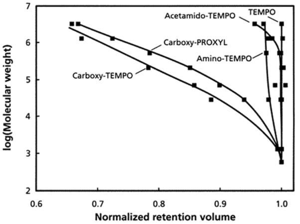
SEC calibration curves of 50 × 8 mm I.D. poly(styrene-co-divinylbenzene) monoliths prepared at a temperature of 130 °C using 85:15 PEG-decanol porogen and different stable free radicals at a molar ratio of 1.3 to 1 with respect to benzoyl peroxide. Reproduced from ref. [205] with permission.
Recently, Kanamori et al. used a porogenic mixture containing polymer to prepare porous poly(divinylbenzene) monoliths [206]. Their polymerization mixtures comprised divinylbenzene, 1,3,5-trimethylbenzene, as well as dimethylsiloxane and the polymerization carried out at 125 °C in glass ampoules was initiated using a system consisting of TEMPO, acetic anhydride, and benzoyl peroxide. Under optimized conditions, the morphology of the monolith resembles that of silica-based monolith featuring porous skeletons with large through pores shown in Fig. 23 and remarkably high surface areas exceeding 600 m2/g. The authors conclude from these results that the skeletons must consist of agglomerated nanoparticles less than 10 nm in size that further aggregate to form larger secondary particles ranging in size from few tens to hundred nanometers that then form the skeletons. Unfortunately, no chromatographic and hydrodynamic characteristics are available yet for these interesting materials.
Fig. 23.
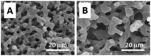
Scanning electron microscopy images of poly(divinylbenzene) monoliths prepared with increasing percentage of polymer porogen in the polymerization mixture composed of divinylbenzene, 1,3,5-trimethylbenzene, dimethylsiloxane, TEMPO, acetic anhydride, and benzoyl peroxide. Reproduced from ref. [206] with permission.
Once the polymerization reaction is stopped by decreasing the temperature or because all the monomers are exhausted, the free radical capped with the TEMPO modulator remain dormant in the monolith and can be potentially reused. This feature is beneficial for functionalization of the pore surface using the “grafting from” technique which means that the radical residing at the pore surface can be reactivated and initiate polymerization that starts radical present at the surface. The pores are simply filled with a new monomer and the column heated to the reaction temperature. The dormant radicals become active and initiated polymerization that starts at the pore surface and protrudes in the pore. The extent of grafting is readily controlled by time. The major advantage is the disconnection of the porous structure formation from its functionalization. We first demonstrated this option using very simple experiment including grafting of poly(styrene-co-divinylbenzene) monolith with 2-hydroxyethyl methacrylate and chloromethylstyrene followed by monitoring occurrence of new peaks in FT-IR spectra [47]. More detailed experiments with additional monomers such as t-butyl methacrylate and 4-vinylpyridine showed that significant quantities of grafts can be formed in pores at a temperature equaling that used for polymerization of the monolith [204].
6.2. Organotellurium initiators
The nitroxide-mediated polymerization described in section 4.1 depends on reversible generation of a free radical located at terminal carbon atom of the chain and persistent nitroxyl radical capping the chain end. Organotellurium-mediated living radical polymerization follows a similar rule [207,208]. The carbon-tellurium bond of the organotellurium unimolecular initiator such as 1-phenyl-1-methyltellanylethane 25 (Fig. 24) cleaves at a higher temperature and forms a carbon-centered free radical that initiates the polymerization until it combines with the tellurium radical. Thus, styrene is polymerized at a temperature of 105 °C for 18 h to achieve ca. 90% conversion [207]. An addition of azobisisobutyronitrile to the polymerization mixture significantly accelerates the kinetics and a similar conversion is achieved at 60 °C in only 11 h [208].
Fig. 24.
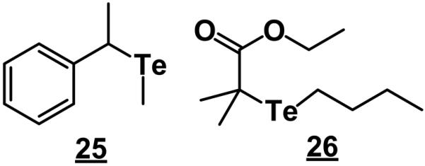
Examples of tellurium containing initiators.
Kanamori's group was intrigued by this unusual approach and used it also for the preparation of porous monoliths from 80% grade divinylbenzene [209]. The initiator was a 2:1 mixture of ethyl-2-methyl-2-butyltellanyl propionate 26 and azobisisobutyronitrile. They used again 1,3,5-trimethylbenzene, and dimethylsiloxane as porogens and run the polymerization at 80 °C for 24 h. The bi-continuous morphology of the monolith is controlled by addition of the polymer porogen and exhibits features similar to that shown in Fig. 23. No pores are formed in absence of the polymer porogen while even a small percentage of dimethylsiloxane triggers spinoidal phase separation and formation of large pores in the micrometer range. More surprisingly, these monolith exhibit surface areas of up to 860 m2/g, a value quite unusual for monoliths. The formation of rather large surface area is attributed to a secondary phase separation that occurs within the gelling phase and develops the “skeletal” pores [209].
The major advantage of using organotellurium compounds as a part of the initiation system is their easier preparation in a variety of structures and facile functionalization. Also, the high surface areas attainable using this method may facilitate the separations of small molecules in isocratic mode. The downturn is much less experience with this type of polymerization and completely missing preparation of columns and chromatographic evaluation of their performance.
6.3 Atom transfer radical polymerization
Atom transfer radical polymerization (ATRP) has been introduced by Matyjaszewski in the mid 1990s [210] and is now widely used in the preparation of well defined polymers and copolymers [211]. Despite the popularity of this technique in general polymer chemistry, its use in the preparation of monoliths is very limited. Kanamori et al. described its application for the preparation of monoliths from a pure crosslinker, 1,3-glycerol dimethacrylate 7 [212]. The polymerization mixture first consisted of this monomer, hexamethyltriethylenetetramine, copper(I) bromide, and methyl-α-bromophenylacetate dissolved in dimethylformamide. However, this monolith did not exhibit any porosity after drying. Incorporation of poly(ethylene oxide) (PEO) with a molecular mass of 100,000 enabled formation of a bicontinuous porous structure which parameters depended on percentages of the monomer, PEO, and solvent in the mixture. Varying these parameters, monoliths with mean pore sizes ranging from 70 to 900 nm could be obtained.
The authors argue that there is a significant difference between preparation of monolithic structures using typical free radical polymerization and ATRP. The former leads to heterogeneous crosslinking due to uncontrolled termination of formed polymers that being “dead” from the kinetic point of view serve then as microgels that coalesce and form the well known aggregates of microglobules. In contrast, living free radical polymerizations affords a highly homogeneous crosslinking due to isotropic spinoidal decomposition induced through the presence of another polymeric agent, PEO. Indeed, SEM micrographs indicate that morphology of monolith prepared from analogous mixtures using ATRP approach and standard radical polymerization thermally initiated with azobisisobutyronitrile are completely different.
While this study focuses on morphological features of the monoliths and measurements of pore size distributions using mercury intrusion porosimetry, it falls short in presenting the effect of this polymerization technique on the extent of surface area which increase is desirable. Also, all experiments were carried out in glass ampoules and the transfer of this approach to columns and testing of their chromatographic performance has yet to be demonstrated.
6.4 Ring opening metathesis polymerization
The ring opening metathesis emerged in the mid 1970 [213,214] and soon became an indispensable tool in organic chemistry. Its value has been recognized by awarding the 2005 Nobel Prize in chemistry to Chauvin, Grubbs, and Schrock. This reaction has also been used in polymerizations thus enabling the preparation of a variety of polymers with interesting properties [215]. In 2000, Sinner and Buchmeiser introduced ring opening metathesis polymerization (ROMP) in the field of monoliths [216,217] and in detail described in several reviews [6,27,218,219].
Initially, monomers used in this technique were derivatives of norbornene (Fig 25). For example, a mixture of norbornene 27, exo,endo-1,4,4a,5,8,8a-hexahydro-1,4,5,8-exo,endo-dimethano-naphthalene 28 (crosslinker), toluene and propanol (porogens) was polymerized in the presence of ruthenium complex 29 (catalyst) in a 3 mm I.D. glass tube (mold) at room temperature overnight to afford a porous monolith [216]. The porous properties were again a function of the percentage of crosslinker, composition of the porogenic mixture, concentration of initiator, and temperature clearly indicating that the phase separation and reaction kinetics are again at play. The glass tube was functionalized with norborn-2-ene-5-yltrichlorosilane 30 in order to avoid detachment of the monolith from the wall. The polymerization itself proceeds in a sealed test tube in which the column tube open at both end is placed and completely covered with the polymerization mixture. Once the polymerization process is complete, the test tube is broken and the mold with the monolith inside recovered.
Fig 25.
Examples of monomers used in the ring opening metathesis polymerization affording porous monoliths.
Obviously, this process can be easily transferred to fused silica capillaries since chemistry of glass and silica is similar. Morphologies of monoliths prepared in 3 mm I.D. column and 200 μm I.D. capillary are compared in Fig. 26 [220] The difference is striking. Microglobules of the monolith prepared within the capillary feature a rough surface. In contrast, polymer prepared in glass tube is built from larger microglobules which surface appears smooth and well defined. Interestingly, measurements of the permeability to flow did not reveal any significant difference between both formats. However, the chromatographic performance of capillaries was much better than that of their 3 mm I.D. counterparts. The peak width in the latter was twice as large as in the former [220].
Fig. 26.
SEM micrographs of monolith prepared using ROMP process in a 3 mm I.D. column and 200 μm I.D. capillary. Reproduced from ref. [220] with permission.
The effect of downscaling of this technique was recently studied in a greater detail [221]. Sinner et al. used capillaries with a diameter of 200, 100, and 50 μm but did not observe any difference in the morphology of the resulting monoliths. They only noticed a higher variability in repeatibility of permeability in series of columns prepared under identical conditions in narrower capillaries. They ascribe this behavior to the more pronounced effect of irregularities in the porous structure due to the increasing ratio of pore size to the capillary diameter.
The original procedure involving norbornene derived monomers was later extended to other cyclic monomers [222,223]. For example, cis-cyclooctene 31was copolymerized with tris(cyclooct-4-ene-1-yloxy)methylsilane crosslinker 32 to afford monoliths with well developed microglobular structure suitable for the separation of proteins [224].
The living character of polymerization facilitates the surface functionalization. The procedure is similar to that outlined in section 6.1. The mold containing monoliths is recovered, provided with end fittings, and attached to a pump. First, a solvent is pumped through to remove all liquid contents from the pores. Then the pores are filled with a solution of the functional monomer and the grafting polymerization carried out at a higher temperature. The grafting was demonstrated using a variety of functionalized norbornenes and 7-oxanorbornes [216].
7 Polycondensation
Vast majority of monoliths have been prepared using chain-growth polymerization such as free radical polymerization. In these techniques the polymer chain propagates during the entire polymerization process via a reaction of monomer molecules with the polymer chain that bears the active site located at its end. In contrast, step-growth polymerization also called polycondensation features repeated activation of the chain end thus allowing for growth of all polymer chains in the system no matter how long they are. These reactions are not sensitive to oxygen and the careful de-aeration essential for free radical processes is not needed. Recently, polycondensation became a new contribution to the family of methods enabling the preparation of monoliths.
Urea-formaldehyde polymer was the first chromatographic monolith prepared using polycondensation [225]. Its preparation is simple. An acidified aqueous solution of urea and formaldehyde is mixed together and poured in a stainless steel tube. After a short period of reaction at room temperature, the final curing is achieved at 60 °C in several hours. The monolith was formed from aggregated 2 μm irregular particles and had a surface area of 42 m2/g. The imine functionalities of the resin then reacted with a triazine dye Cibachrom blue F3GA, which is a well known group-selective ligand broadly applied in affinity chromatography. The dynamic loading capacity of this column for lysozyme was 1 mg/mL. Its specificity was demonstrated with the isolation of bovine serum albumin (BSA) from the newborn calf serum. While BSA was retained at pH 7.0 Tris buffer, all other proteins were eluted. Albumin was then recovered using 1 mol/L sodium chloride solution in the Tris buffer.
Monomers containing epoxy groups shown in Fig. 27 were used more often. Hosoya's group demonstrated the preparation of porous monoliths using polycondensation of bisphenol A diglycidyl ether (BADE) 33 with 4,4′-methylene-bis-cyclohexylamine 34 dissolved in low molecular weight oligo(ethylene glycol) and carried out at temperatures 80-160 °C for 4 h [226]. Their initial study was then extended and focused on the morphology of the resin as a function of the composition of polymerization mixture [227]. Their polymers exhibited the bicontinuous porous structure with a through pore size in single micrometers. However, the surface areas of these polymers did not exceed 10 m2/g indicating that the skeletons were not porous.
Fig. 27.
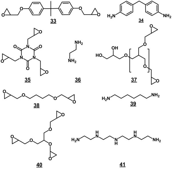
Examples of reaction partners used for the preparation of monoliths using polycondensation reaction.
Guided by environmental concerns, Li at al. used biodegradable epoxy soybean oil as a solvent and porogen instead of poly(ethylene glycol) for the preparation of BADE -4,4′-methylene-bis-cyclohexylamine monoliths [228]. The morphology of the polymer was completely different from that observed by Hosoya and was formed from epoxy resin matrix containing spherical holes originally filled with phase separated epoxy soybean oil. This closed-cell structure does not appear to be permeable if placed in a column. Interestingly, a polymerization mixture containing 40 % oil afforded monolith with a porosity of only 8.6%. This could be explained by significant shrinkage accompanying the extraction of the epoxy soybean oil from monolith. Another explanation is inclusion of a significant part of the epoxy soybean oil in the resin since it also contains reactive epoxide functionalities.
Since the properties of the BADE based monoliths probably did not appear suitable for the chromatographic applications, Hosoya used tris-(2,3-epoxypropyl)-isocyanurate (TEPIC) 35 as the epoxide containing monomer together with 34 and carried out the polymerization reaction in 100 μm I.D. capillaries, which wall was modified with epoxypropyl-trimethoxysilane [229]. The monolithic structure had 3.3 μm through pores. Unfortunately, optimization of the reaction conditions leading to the monolith used in this work is not presented. The authors found a surface area of 2.7 m2/g and pore volume 0.004 mL/g determined using nitrogen adsorption/desorption. These values are within experimental error of the method and indicate that the monolith in the dry state does not contain any small pores. Surprisingly, this column exhibits almost linear SEC calibration curve in the range from benzene to polystyrene standard with a molecular weight of 20×106 with a significant volume of pores engaged in this separation. Unfortunately, no explanation is suggested to reconcile these controversial findings. Perhaps, the matrix swells upon the solvation with the mobile phase that always contains acetonitrile. The authors demonstrate the application of this monolithic column with separations of various compounds in both reversed phase and hydrophilic interaction modes. The column efficiency for benzene is claimed to be 47 200 plates/m.
Wand and Zhang used a similar procedure in which BADE was condensed with ethylenediamine 36 in the presence of poly(ethylene glycol) 1000 in a 10 × 1 cm I.D. glass tube [230]. The morphology of this monolith is somewhat similar to that observed by Hosoya. This column was used without any further modification for preconcentration of lead ions and exhibited a loading capacity of 106.8 mg Pb2+/g with recoveries over 95%. While anions and alkali metal and alkali earth metal ions did not interfere with the sorption of lead ions, transition metal ions significantly affected the sorption properties thus making the resin less suitable for preconcentration of complex samples.
Commercially available poly(glycerol-3-glycidyl ether) 37 is another epoxy groups containing precursor suitable for the preparation of hydrophilic monoliths [231]. This compound was dissolved in porogenic solvent comprising toluene and methyl t-butyl ether and after admixing a catalyst, boron trifluoride, the mixture was transferred in silanized glass column. The crosslinking was left to proceed at room temperature for 1 h. Monolith prepared under these conditions contained both hydroxyl and epoxide functionalities. Its pore size as large as 22 μm makes it an ideal support for the affinity capturing of whole cells. The residual epoxide functionalities were first hydrolyzed to a diol, activated with 1,1′-carbonyldiimidazole, followed by immobilization of the Polymyxin B ligand. The binding capacity of a 6×4.5 mm I.D. monolithic column was 4×10⁹ E. coli cells as determined by frontal elution and did not depend on the flow rate. The elution of all captured cells without affecting their viability was achieved using carbonate buffer pH 8.2.
Nguyen and Irgum made an attempt at the preparation of monolith from oil-in-water emulsions of a mixture of BADE 8 or 1,4-butanediol diglycidyl ether 38 (BDDE), surfactant (Pluronic L101 or Pluronic P123), and porogen (diethylene glycol dibutyl ether, diethylene glycol diethyl ether, or poly(tetrahydrofuran)) in 0.1 mol/L aqueous solution of calcium chloride containing diaminohexane 39 [232]. Their early experiments with polycondensations mostly afforded monoliths than could be characterized as an array of fused spherical particles. However, further work led to discovery of a system consisting of 1:1 BADE and BDDA epoxy component and 60% of stoichiometric amount of diamine that provided for a structure similar to that of silica-based monoliths. The through pore size of this monolith measured using mercury intrusion porosimetry was 1.8 μm and the surface area was ca 2 m2/g. Once again, this small surface area can result from shrinkage during the drying.
In continuation of this research, they also prepared monoliths from more complex mixtures that allowed them to better control the morphology and porosity [233]. For example, Fig. 28 shows a monolith with a well developed bicontinuous structure prepared from an oil phase composed of BADE 33, BDDE 38, and glyceryl triglycidyl ether 40 dissolved in diethylene glycol diethyl ether dispersed in the continuous aqueous phase containing a mixture of diaminohexane 39 and tetraethylenepentamine 41. This monolith contained a significant amount of hydroxyl functionalities (4.7 mmol/g) that provide the monolith with hydrophilic properties. Its pore size was again centered at 1.8 μm but a slightly higher surface area of 4.5 m2/g was found in the dry state. 2H NMR cryoporosimetry carried out with monolith swollen in water-deuterium oxide mixture indicated presence of hydrogels which may explain separation properties of the similar monolith prepared by Hosoya [229]. These unusual monoliths certainly exhibit remarkable morphological structures. However, their performance in separations has yet to be demonstrated.
Fig. 28.
SEM micrographs of epoxy monoliths prepared from 45% organic phase consisting of epoxide monomer mixture of 1,4-butanediol diglycidyl ether, bisphenol A diglycidyl ether glyceryl triglycidyl ether (4.5:4.5:1) and diethylene glycol dibutyl ether, dispersed in the aqueous phase containing 20% diethylene glycol diethyl ether as the cosurfactant and 80% of the stoichiometric amount of diaminohexane and tetraethylenepentamine (9.7:1) dissolved in 0.1 calcium chloride solution. Reproduced from ref. [233] with permission.
8 Preparation of monoliths from soluble polymers
Probably the most unprecedented yet simple approach to porous polymer monoliths has been developed by Irgum's group in Sweden. They prepared monolithic materials from a ready-made polymer, a linear polyamide [234]. The proof of concept was demonstrated with fishing line polyamide dissolved at 130 °C in benzyl alcohol followed by controlled slow cooling in a capillary to achieve precipitation of the polymer and formation of the monolith. Benzyl alcohol was chosen since it does not dissolve polyamide at the room temperature. They explored the effects of concentration of polyamide solution and speed of cooling on morphology of the monoliths and found that monolith prepared under optimized conditions contains large through pores and has a surface area of about 7 m2/g indicating again absence of mesopores.
The follow up study published recently focuses on the effects of multiple parameters not considered in the early communication such as chemical nature of the polyamides shown in Fig. 29, time the solution spent at high temperature during dissolution, presence of oxygen and water on morphology of the monolith [235]. The structure and molecular weight of polyamide affects the ease of dissolution. For example, polyamide 46 and 66 did not dissolve under given conditions at all. Polyamide 69 afforded monolith that collapsed under drying and structure of monolith prepared from polyamide 6/66 was not suitable for flow through applications. The best monoliths with surface areas reaching up to almost 60 m2/g having a pore size of 2 μm were produced from polyamides 6 and 610. Morphological features of these monoliths are presented in Fig. 30. This figure also shows the wide variety of structures this method may offer.
Fig. 29.
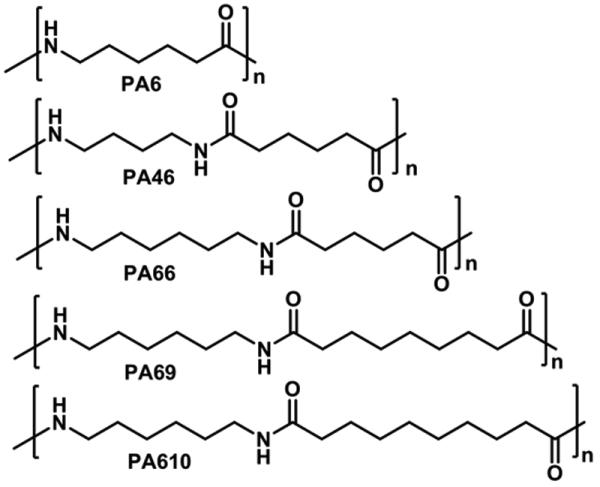
Structures of soluble polyamides used for the preparation of monoliths via phase separation.
Fig. 30.
SEM micrographs of monolith prepared from polyamides. Reproduced from ref. [235] with permission.
The effects of both length of keeping the solution at 130 °C and water were ascribed to degradation of polymers. In contrast, oxygen oxidizes benzyl alcohol to benzaldehyde that then reacts with terminal amine groups of polyamide and changes it properties. Although the initial work has been completed, the hydrodynamic properties, resistance to compression and applications of these unusual monoliths have not been tested. Provided these monoliths would exhibit good performance in applications, this simple process can be also used for the preparation cheap large size units and perhaps extended to other polymers.
9 Conclusions
The text presented above clearly demonstrates the rapid development of the area of monolithic technologies. The porous monoliths are still young and explorations in their field will certainly lead to discoveries of novel materials and shapes with unexpected properties and applications. For example, the new polymerization mechanisms and chemistries such as electron beam initiated polymerization, ring-opening metathesis polymerization, polycondensation of epoxides, and precipitation described in this review emerged just in the last few years. These newly developed monoliths also result in new morphologies that may enable fast separations and new selectivities. Since polymer chemistry is really rich in options, this trend will continue. Formation of monoliths via grafting and crosslinking of aggregated submicrometer sized particles presented recently by Morbidelli's group [236] is one example of new directions. We can also expect new discoveries related to miniaturization of separation devices containing monoliths in both narrow bore capillaries and microfluidic chips. Although this development may look trivial since it appears to only involve a decrease in size and shape of the cross section, the effect of confinement in very narrow conduits can be significant [57,237,238].
Although this review focused on columnar formats, monoliths in new shapes are also emerging. For example thin monolithic layers we are developing facilitate very simple 2D separations of peptides and enable their direct mass spectrometric detection [239,240]. Recently developed superhydrophobic monolithic layers allow photopatterning of functional monomers through a mask thus generating three-dimensional patterns of chemistry that permeate the entire bulk of the material [241]. The channels are simply defined by the difference in surface tension. Consequently, microchips can be created on the plate without need for any fabrication. It is safe to assume that these materials are likely to find a number of applications in both separation science and diagnostics.
Acknowledgement
Support of this work by grants of the National Institute Institutes of Health (GM-48364 and EB-006133) is gratefully acknowledged. This work was also supported by the Director, Office of Science, Office of Basic Energy Sciences, Materials Sciences and Engineering Division, of the U.S. Department of Energy under Contract No. DE-AC02-05CH11231.
Footnotes
Publisher's Disclaimer: This is a PDF file of an unedited manuscript that has been accepted for publication. As a service to our customers we are providing this early version of the manuscript. The manuscript will undergo copyediting, typesetting, and review of the resulting proof before it is published in its final citable form. Please note that during the production process errors may be discovered which could affect the content, and all legal disclaimers that apply to the journal pertain.
The nomenclature of pore size categories coined in old IUPAC recommendations [44] does not make much sense at present. Calling pores smaller than 2 nm micropores is clearly misleading since the prefix micro implies size in micrometers. Therefore, analogous to terms mesopores and macropores, a prefix independent of the size unit such as minipores or similar would be more appropriate. Alternatively, a term nanopores would also be more appropriate.
References
- 1.Tsvett MS. Ber. Deut. Botan. Gessel. 1906;24:322. [Google Scholar]
- 2.Hjertén S. Ind. Eng. Chem. Res. 1999;38:1205. [Google Scholar]
- 3.Regnier FE. HRC-J. 2000;23:19. [Google Scholar]
- 4.Svec F, Peters EC, Sýkora D, Fréchet JMJ. J. Chromatogr. 2000;887:3. doi: 10.1016/s0021-9673(99)01232-7. [DOI] [PubMed] [Google Scholar]
- 5.Josic D, Buchacher A, Jungbauer A. J. Chromatogr. B. 2001;752:191. doi: 10.1016/s0378-4347(00)00499-0. [DOI] [PubMed] [Google Scholar]
- 6.Buchmeiser MR. J. Chromatogr. 2001;918:233. doi: 10.1016/s0021-9673(00)00129-1. [DOI] [PubMed] [Google Scholar]
- 7.Tanaka N, Kobayashi H, Nakanishi K, Minakuchi H, Ishizuka N. Anal. Chem. 2001;73:420A. doi: 10.1021/ac012495w. [DOI] [PubMed] [Google Scholar]
- 8.Tanaka N, Kobayashi H, Ishizuka N, Minakuchi H, Nakanishi K, Hosoya K, Ikegami T. J. Chromatogr. A. 2002;965:35. doi: 10.1016/s0021-9673(01)01582-5. [DOI] [PubMed] [Google Scholar]
- 9.Siouffi A-M. J. Chromatogr. A. 2003;1000:801. doi: 10.1016/s0021-9673(03)00510-7. [DOI] [PubMed] [Google Scholar]
- 10.Jungbauer A, Hahn R. J. Sep. Sci. 2004;27:767. doi: 10.1002/jssc.200401812. [DOI] [PubMed] [Google Scholar]
- 11.Cabrera K. J. Sep. Sci. 2004;27:843. doi: 10.1002/jssc.200401827. [DOI] [PubMed] [Google Scholar]
- 12.Miyabe K, Guiochon G. J. Sep. Sci. 2004;27:853. doi: 10.1002/jssc.200401772. [DOI] [PubMed] [Google Scholar]
- 13.Bedair M, El Rassi Z. Electrophoresis. 2004;25:4110. doi: 10.1002/elps.200406136. [DOI] [PubMed] [Google Scholar]
- 14.Svec F. J. Sep. Sci. 2004;27:1419. doi: 10.1002/jssc.200401825. [DOI] [PubMed] [Google Scholar]
- 15.Vegvari A. J. Chromatogr. A. 2005;1079:50. doi: 10.1016/j.chroma.2005.03.122. [DOI] [PubMed] [Google Scholar]
- 16.Rieux L, Niederlaender H, Verpoorte E, Bischoff R. J. Sep. Sci. 2005;28:1628. doi: 10.1002/jssc.200500146. [DOI] [PubMed] [Google Scholar]
- 17.Svec F. Electrophoresis. 2006;27:947. doi: 10.1002/elps.200500661. [DOI] [PubMed] [Google Scholar]
- 18.Svec F, Huber CG. Anal. Chem. 2006;78:2100. doi: 10.1021/ac069383v. [DOI] [PubMed] [Google Scholar]
- 19.Schaller D, Hilder EF, Haddad PR. J. Sep. Sci. 2006;29:1705. doi: 10.1002/jssc.200600169. [DOI] [PubMed] [Google Scholar]
- 20.Svec F. J. Chromatogr. B. 2006;841:52. doi: 10.1016/j.jchromb.2006.03.055. [DOI] [PubMed] [Google Scholar]
- 21.Guiochon G. J. Chromatogr. A. 2007;1168:101. doi: 10.1016/j.chroma.2007.05.090. [DOI] [PubMed] [Google Scholar]
- 22.Chambers SD, Glenn KM, Lucy CA. J. Sep. Sci. 2007;30:1628. doi: 10.1002/jssc.200700090. [DOI] [PubMed] [Google Scholar]
- 23.Jungbauer A, Hahn R. J. Chromatogr. A. 2008;1184:62. doi: 10.1016/j.chroma.2007.12.087. [DOI] [PubMed] [Google Scholar]
- 24.Wu R, Hu L, Wang F, Ye M, Zou H. J. Chromatogr. A. 2008;1184:369. doi: 10.1016/j.chroma.2007.09.022. [DOI] [PubMed] [Google Scholar]
- 25.Svec F, Kurganov AA. J. Chromatogr. A. 2008;1184:281. doi: 10.1016/j.chroma.2007.07.014. [DOI] [PMC free article] [PubMed] [Google Scholar]
- 26.Vlakh EG, Tennikova TB. J. Chromatogr. A. 2009;1216:2637. doi: 10.1016/j.chroma.2008.09.090. [DOI] [PubMed] [Google Scholar]
- 27.Svec F, Tennikova TB, Deyl Z. Monolithic materials: Preparation, Properties, and Applications. Elsevier; Amsterdam: 2003. [Google Scholar]
- 28.Mould DL, Synge RLM. Analyst. 1952;77:964. [Google Scholar]
- 29.Mould DL, Synge RLM. Biochem. J. 1954;58:571. doi: 10.1042/bj0580571. [DOI] [PMC free article] [PubMed] [Google Scholar]
- 30.Kubín M, Špaček P, Chromeček R. Coll. Czechosl. Chem. Commun. 1967;32:3881. [Google Scholar]
- 31.Ross WD, Jefferson RT. J. Chrom. Sci. 1970;8:386. [Google Scholar]
- 32.Hileman FD, Sievers RE, Hess GG, Ross WD. Anal. Chem. 1973;45:1126. [Google Scholar]
- 33.Schnecko H, Bieber O. Chromatographia. 1971;4:109. [Google Scholar]
- 34.Hjertén S, Liao JL, Zhang R. J. Chromatogr. 1989;473:273. [Google Scholar]
- 35.Hjertén S, Mohammad J, Nakazato K. J. Chromatogr. A. 1993;646:121. [Google Scholar]
- 36.Tennikova TB, Svec F, Belenkii BG. J. Liquid Chromatogr. 1990;13:63. [Google Scholar]
- 37.Tennikova TB, Bleha M, Svec F, Almazova TV, Belenkii BG. J. Chromatogr. 1991;555:97. [Google Scholar]
- 38.Svec F, Fréchet JMJ. Anal. Chem. 1992;54:820. [Google Scholar]
- 39.Minakuchi H, Nakanishi K, Soga N, Ishizuka N, Tanaka N. Anal. Chem. 1996;68:3498. doi: 10.1021/ac960281m. [DOI] [PubMed] [Google Scholar]
- 40.Tanaka N, Ishizuka N, Hosoya K, Kimata K, Minakuchi H, Nakanishi K, Soga N. Kuromatogurafi. 1993;14:50. [Google Scholar]
- 41.Fields SM. Anal. Chem. 1996;68:2709. doi: 10.1021/ac951247v. [DOI] [PubMed] [Google Scholar]
- 42.Yuan HG, Kalfas G, Ray WH. J. Macromol. Sci., Chem. Phys. C31. 1991:215. [Google Scholar]
- 43.Svec F, Fréchet JMJ. Chem. Mater. 1995;7:707. [Google Scholar]
- 44.Everett DH. Pure Appl. Chem. 1972;31:577. [Google Scholar]
- 45.Viklund C, Svec F, Fréchet JMJ, Irgum K. Chem. Mater. 1996;8:744. [Google Scholar]
- 46.Svec F, Fréchet JMJ. Macromolecules. 1995;28:7580. [Google Scholar]
- 47.Peters EC, Svec F, Fréchet JMJ, Viklund C, Irgum K. Macromolecules. 1999;32:6377. [Google Scholar]
- 48.Svec F, Hradil J, Čoupek J, Kálal J. Angew. Macromol. Chem. 1975;48:135. [Google Scholar]
- 49.Huo Y, Schoenmakers PJ, Kok WT. J. Chromatogr. A. 2007;1175:81. doi: 10.1016/j.chroma.2007.10.048. [DOI] [PubMed] [Google Scholar]
- 50.Eeltink S, Hilder EF, Geiser L, Svec F, Fréchet JMJ, Rozing GP, Schoenmakers PJ, Kok WT. J. Sep. Sci. 2007;30:407. doi: 10.1002/jssc.200600316. [DOI] [PubMed] [Google Scholar]
- 51.Dong X, Dong J, Ou J, Zhu Y, Zou H. Electrophoresis. 2006;27:2518. doi: 10.1002/elps.200500865. [DOI] [PubMed] [Google Scholar]
- 52.Okanda FM, El Rassi Z. Electrophoresis. 2006;27:1020. doi: 10.1002/elps.200500766. [DOI] [PubMed] [Google Scholar]
- 53.Zhong H, El Rassi Z. J. Sep. Sci. 2009;32:10. doi: 10.1002/jssc.200900127. [DOI] [PubMed] [Google Scholar]
- 54.Le Gac S, Carlier J, Camart JC, Cren-Olive C, Rolando C. J. Chromatogr. B. 2004;808:3. doi: 10.1016/j.jchromb.2004.03.067. [DOI] [PubMed] [Google Scholar]
- 55.Hradil J, Horák D. React. Funct. Polym. 2005;62:1. [Google Scholar]
- 56.Danquah MK, Forde GM. J. Chromatogr. A. 2008;1188:227. doi: 10.1016/j.chroma.2008.02.045. [DOI] [PubMed] [Google Scholar]
- 57.He M, Zeng Y, Sun X, Harrison DJ. Electrophoresis. 2008;29:2980. doi: 10.1002/elps.200800040. [DOI] [PubMed] [Google Scholar]
- 58.Santora BP, Gagne MR, Moloy KG, Radu NS. Macromolecules. 2001;34:658. [Google Scholar]
- 59.Zhu G, Yang C, Zhang L, Liang Z, Zhang W, Zhang Y. Talanta. 2006;70:2. doi: 10.1016/j.talanta.2005.12.037. [DOI] [PubMed] [Google Scholar]
- 60.Moore RE, Licklider L, Schumann D, Lee TD. Anal. Chem. 1998;70:4879. doi: 10.1021/ac980723p. [DOI] [PubMed] [Google Scholar]
- 61.Hird N, Hughes I, Hunter D, Morrison MT, Sherrington DC, Stevenson L. Tetrahedron. 1999;55:9575. [Google Scholar]
- 62.Xiong BH, Zhang LH, Zhang YK, Zou HF, Wang JD. J. High Resolut. Chromatogr. 2000;23:67. [Google Scholar]
- 63.Jin W, Fu H, Huang X, Xiao H, Zou HF. Electrophoresis. 2003;24:3172. doi: 10.1002/elps.200305579. [DOI] [PubMed] [Google Scholar]
- 64.Premstaller A, Oberacher H, Huber CG. Anal. Chem. 2000;72:4386. doi: 10.1021/ac000283d. [DOI] [PubMed] [Google Scholar]
- 65.Walcher W, Oberacher H, Troiani S, Holzl G, Oefner PJ, Zolla L, Huber CG. J. Chromatogr. B. 2002;782:111. doi: 10.1016/s1570-0232(02)00667-0. [DOI] [PubMed] [Google Scholar]
- 66.Oberacher H, Huber CG. Trends Anal. Chem. 2002;21:166. [Google Scholar]
- 67.Tholey A, Toll H, Huber CG. Anal. Chem. 2005;77:4618. doi: 10.1021/ac050538t. [DOI] [PubMed] [Google Scholar]
- 68.Bisjak CP, Bakry R, Huck CW, Bonn GK. Chromatographia. 2005;62:31. [Google Scholar]
- 69.Svec F, Deyl Z, Svec F, editors. Capillary Electrochromatography. Elsevier; Amsterdam: 2001. p. 183. [Google Scholar]
- 70.Peters EC, Petro M, Svec F, Fréchet JMJ. Anal. Chem. 1997;69:3646. doi: 10.1021/ac970377w. [DOI] [PubMed] [Google Scholar]
- 71.Peters EC, Petro M, Svec F, Fréchet JMJ. Anal. Chem. 1998;70:2288. doi: 10.1021/ac9713518. [DOI] [PubMed] [Google Scholar]
- 72.Peters EC, Petro M, Svec F, Fréchet JMJ. Anal. Chem. 1998;70:2296. doi: 10.1021/ac9713520. [DOI] [PubMed] [Google Scholar]
- 73.Jandera P, Urban J, Planeta J. J. Sep. Sci. 2003;26:1005. [Google Scholar]
- 74.Ueki Y, Umemura T, Li J, Odake T, Tsunoda K. Anal. Chem. 2004;76:7007. doi: 10.1021/ac040079g. [DOI] [PubMed] [Google Scholar]
- 75.Canto-Mirapeix A, Herrero-Martinez JM, Mongay-Fernandez C, Simo-Alfonso EF. Electrophoresis. 2008;29:4399. doi: 10.1002/elps.200800317. [DOI] [PubMed] [Google Scholar]
- 76.Courtois J, Bystrom E, Irgum K. Polymer. 2006;47:2603. [Google Scholar]
- 77.Palm A, Novotny MV. Anal. Chem. 1997;69:4499. [Google Scholar]
- 78.Kubo T, Kimura N, Hosoya K, Kaya K. J. Polym. Sci., Polym. Chem. 2007;45:3811. [Google Scholar]
- 79.Li Y, Tolley HD, Lee ML. Anal. Chem. 2009;81:4406. doi: 10.1021/ac900364d. [DOI] [PubMed] [Google Scholar]
- 80.Aoki H, Kubo T, Ikegami T, Tanaka N, Hosoya K, Tokuda D, Ishizuka N. J. Chromatogr. A. 2006;1119:66. doi: 10.1016/j.chroma.2006.01.133. [DOI] [PubMed] [Google Scholar]
- 81.Sinitsyna ES, Sergeeva Y, Vlakh EG, Saprikina NN, Tennikova TB. React. Funct. Polym. 2009;69:385. [Google Scholar]
- 82.Cooper AI, Hems WP, Holmes AB. Macromolecules. 1999;32:2156. [Google Scholar]
- 83.Cooper AI, Holmes AB. Adv. Mater. 1999;11:1270. [Google Scholar]
- 84.Cooper AI. J. Mater. Chem. 2000;10:207. [Google Scholar]
- 85.Cooper AI. Adv. Mater. 2003;15:1049. [Google Scholar]
- 86.Kang SR, Ju CS. Hwahak Konghak. 2005;43:21. [Google Scholar]
- 87.Hebb AK, Senoo K, Cooper AI. Composites Sci. Technol. 2003;63:2379. [Google Scholar]
- 88.Viklund C, Pontén E, Glad B, Irgum K, Hörsted P, Svec F. Chem. Mater. 1997;9:463. [Google Scholar]
- 89.Bedair M, El Rassi Z. J. Chromatogr. A. 2005;1079:236. doi: 10.1016/j.chroma.2005.02.084. [DOI] [PubMed] [Google Scholar]
- 90.Bedair M, El Rassi Z. Electrophoresis. 2002;23:2938. doi: 10.1002/1522-2683(200209)23:17<2938::AID-ELPS2938>3.0.CO;2-8. [DOI] [PubMed] [Google Scholar]
- 91.Chaisuwan P, Nacapricha D, Wilairat P, Jiang Z, Smith NW. Electrophoresis. 2008;29:2301. doi: 10.1002/elps.200700689. [DOI] [PubMed] [Google Scholar]
- 92.Jiang Z, Smith NW, Ferguson PD, Taylor MR. J. Sep. Sci. 2009;31:2774. doi: 10.1002/jssc.200800124. [DOI] [PubMed] [Google Scholar]
- 93.Chen WY, Chen YC. Anal. Chem. 2007;79:2394. doi: 10.1021/ac0614893. [DOI] [PubMed] [Google Scholar]
- 94.Zhao Q, Li XF, Le XC. Anal. Chem. 2008;80:3915. doi: 10.1021/ac702567x. [DOI] [PubMed] [Google Scholar]
- 95.Oxelbark J, Legido-Quigley C, Aureliano CSA, Titirici MM, Schillinger E, Sellergren B, Courtois J, Irgum K, Dambies L, Cormack PAG, Sherrington DC, De Lorenzi E. J. Chromatogr. A. 2007;1160:215. doi: 10.1016/j.chroma.2007.05.057. [DOI] [PubMed] [Google Scholar]
- 96.Courtois J, Fischer G, Sellergren B, Irgum K. J. Chromatogr. A. 2006;1109:92. doi: 10.1016/j.chroma.2005.12.014. [DOI] [PubMed] [Google Scholar]
- 97.Pan Z, Zou HF, Mo W, Huang Xi., Wu R. Anal. Chim. Acta. 2002;466:141. [Google Scholar]
- 98.Xu Z, Yang L, Wang Q. J. Chromatogr. A. 2009;1216:3098. doi: 10.1016/j.chroma.2009.01.089. [DOI] [PubMed] [Google Scholar]
- 99.Gu B, Li Y, Lee ML. Anal. Chem. 2007;79:5848. doi: 10.1021/ac0623585. [DOI] [PubMed] [Google Scholar]
- 100.Trojer L, Bisjak CP, Wieder W, Bonn GK. J. Chromatogr. A. 2009;1216:6303. doi: 10.1016/j.chroma.2009.07.010. [DOI] [PubMed] [Google Scholar]
- 101.Wang Q, Svec F, Fréchet JMJ. J. Chromatogr. A. 1994;669:230. doi: 10.1016/0021-9673(94)80352-8. [DOI] [PubMed] [Google Scholar]
- 102.Viklund C, Irgum K. Macromolecules. 2000;33:2539. [Google Scholar]
- 103.Xie S, Svec F, Fréchet JMJ. J. Polym. Sci., Polym. Chem. 1997;35:1013. [Google Scholar]
- 104.Xie S, Svec F, Fréchet JMJ. Polymer Preprints. 1997;38:211. [Google Scholar]
- 105.Peters EC, Lewandowski K, Petro M, Svec F, Fréchet JMJ. Anal. Commun. 1998;35:83. [Google Scholar]
- 106.Peters EC, Lewandowski K, Petro M, Svec F, Fréchet JMJ. Anal. Commun. 1998;35:83. [Google Scholar]
- 107.Lämmerhofer M, Peters EC, Yu C, Svec F, Fréchet JMJ, Lindner W. Anal. Chem. 2000;72:4614. doi: 10.1021/ac000322l. [DOI] [PubMed] [Google Scholar]
- 108.Xie S, Allington RW, Svec F, Fréchet JMJ. J. Chromatogr. A. 1999;865:169. doi: 10.1016/s0021-9673(99)00981-4. [DOI] [PubMed] [Google Scholar]
- 109.Xie S, Allington RW, Fréchet JMJ, Svec F. Adv. Biochem. Eng. Biotechnol. 2002;76:88. doi: 10.1007/3-540-45345-8_3. [DOI] [PubMed] [Google Scholar]
- 110.Wang Q, Svec F, Fréchet JMJ. Anal. Chem. 1995;67:670. doi: 10.1021/ac00099a028. [DOI] [PubMed] [Google Scholar]
- 111.Müller W. J. Chromatogr. 1990;510:133. [Google Scholar]
- 112.Viklund C, Svec F, Fréchet JMJ, Irgum K. Biotech. Progr. 1997;13:597. doi: 10.1021/bp9700667. [DOI] [PubMed] [Google Scholar]
- 113.Rohr T, Ogeltree DF, Svec F, Fréchet JMJ. Adv. Funct. Mater. 2003;13:265. [Google Scholar]
- 114.Rohr T, Hilder EF, Donovan JJ, Svec F, Fréchet JMJ. Macromolecules. 2003;36:1677. [Google Scholar]
- 115.Rånby B, Yang WT, Tretinnikov O. Nucl. Instrum. Meth. Phys. Res., Sect.B: Beam Interact. Mater. Atoms. 1999;151:301. [Google Scholar]
- 116.Krenkova J, Lacher NA, Svec F. Anal. Chem. 2009;81:2004. doi: 10.1021/ac8026564. [DOI] [PubMed] [Google Scholar]
- 117.Krenkova J, Lacher NA, Svec F. J. Chromatogr. A. 2009;1216:3252. doi: 10.1016/j.chroma.2009.02.036. [DOI] [PubMed] [Google Scholar]
- 118.Connolly D, O'Shea V, Clark P, O'Connor B, Paull B. J. Sep. Sci. 2007;30:3060. doi: 10.1002/jssc.200700365. [DOI] [PubMed] [Google Scholar]
- 119.Gillespie E, Connolly D, Paull B. Analyst. 2009;134:1314. doi: 10.1039/b901300h. [DOI] [PubMed] [Google Scholar]
- 120.Peterson DS, Rohr T, Svec F, Fréchet JMJ. Anal. Chem. 2003;75:5328. doi: 10.1021/ac034108j. [DOI] [PubMed] [Google Scholar]
- 121.Hilder EF, Svec F, Fréchet JMJ. Anal. Chem. 2004;76:3887. doi: 10.1021/ac049732q. [DOI] [PubMed] [Google Scholar]
- 122.Stachowiak TB, Svec F, Fréchet JMJ. Chem. Mater. 2006;18:5950. [Google Scholar]
- 123.Peters EC, Petro M, Svec F, Fréchet JMJ. Anal. Chem. 1998;70:2288. doi: 10.1021/ac9713518. [DOI] [PubMed] [Google Scholar]
- 124.Krenkova J, Gargano A, Lacher NA, Schneiderheinze JM, Svec F. J. Chromatogr. A. 2009;1216:6824. doi: 10.1016/j.chroma.2009.08.031. [DOI] [PubMed] [Google Scholar]
- 125.Peters EC, Svec F, Fréchet JMJ. Adv. Mater. 1997;9:630. [Google Scholar]
- 126.Zhang R, Yang G, Xin P, Qi L, Chen Y. J. Chromatogr. A. 2009;1216:2404. doi: 10.1016/j.chroma.2009.01.023. [DOI] [PubMed] [Google Scholar]
- 127.Hilder EF, Svec F, Fréchet JMJ. J. Chromatogr. A. 2004;1053:101. [PubMed] [Google Scholar]
- 128.Hutchinson JP, Zakaria P, Bowie AR, Macka M, Avdalovic N, Haddad PR. Anal. Chem. 2005;77:407. doi: 10.1021/ac048748d. [DOI] [PubMed] [Google Scholar]
- 129.Zakaria P, Hutchinson JP, Avdalovic N, Liu Y, Haddad PR. Anal. Chem. 2005;77:417. doi: 10.1021/ac048747l. [DOI] [PubMed] [Google Scholar]
- 130.Haddad PR, Hilder EF, Evenhuis C, Schaller D, Pohl C, Flook KJ. Abstr. Papers. American Chemical Society. 2009:236. ANYL. [Google Scholar]
- 131.Svec F. Electrophoresis. 2009 [Google Scholar]
- 132.Yu C, Xu M, Svec F, Fréchet JMJ. J. Polym. Sci., Polym. Chem. 2002;40:755. [Google Scholar]
- 133.Daley AB, Oleschuk RD. J. Chromatogr. A. 2009;1216:772. doi: 10.1016/j.chroma.2008.11.078. [DOI] [PubMed] [Google Scholar]
- 134.Li Y, Gu B, Dennis TH, Lee ML. J. Chromatogr. A. 2009;1216:5525. doi: 10.1016/j.chroma.2009.05.037. [DOI] [PubMed] [Google Scholar]
- 135.Abele S, Nie FQ, Foret F, Paull B, Macka M. Analyst. 2008;133:864. doi: 10.1039/b802693a. [DOI] [PubMed] [Google Scholar]
- 136.Walsh Z, Abele S, Lawless B, Heger D, Klan P, Breadmore MC, Paull B, Macka M. Chem. Commun. 2008:6504. doi: 10.1039/b816958f. [DOI] [PubMed] [Google Scholar]
- 137.Yu C, Svec F, Fréchet JMJ. Electrophoresis. 2000;21:120. doi: 10.1002/(SICI)1522-2683(20000101)21:1<120::AID-ELPS120>3.0.CO;2-H. [DOI] [PubMed] [Google Scholar]
- 138.Fintschenko Y, Choi WY, Ngola SM, Shepodd TJ. Fresenius' J. Anal. Chem. 2001;371:174. doi: 10.1007/s002160100948. [DOI] [PubMed] [Google Scholar]
- 139.Throckmorton DJ, Shepodd TJ, Singh AK. Anal. Chem. 2002;74:784. doi: 10.1021/ac011077o. [DOI] [PubMed] [Google Scholar]
- 140.Augustin V, Proczek G, Dugay J, Descroix S, Hennion MC. J. Sep. Sci. 2007;30:2858. doi: 10.1002/jssc.200700387. [DOI] [PubMed] [Google Scholar]
- 141.Proczek G, Augustin V, Descroix S, Hennion MC. Electrophoresis. 2009;30:515. doi: 10.1002/elps.200800308. [DOI] [PubMed] [Google Scholar]
- 142.Augustin V, Jardy A, Gareil P, Hennion MC. J. Chromatogr. A. 2006;1119:80. doi: 10.1016/j.chroma.2006.02.057. [DOI] [PubMed] [Google Scholar]
- 143.Geiser L, Eeltink S, Svec F, Fréchet JMJ. J. Chromatogr. A. 2007;1140:140. doi: 10.1016/j.chroma.2006.11.079. [DOI] [PMC free article] [PubMed] [Google Scholar]
- 144.Bernabe-Zafon V, Canto-Mirapeix A, Simo-Alfonso EF, Ramis-Ramos G, Herrero-Martinez JM. Electrophoresis. 2009;30:1929. doi: 10.1002/elps.200800553. [DOI] [PubMed] [Google Scholar]
- 145.Bandilla D, Skinner CD. J. Chromatogr. A. 2003;1004:167. doi: 10.1016/s0021-9673(03)00450-3. [DOI] [PubMed] [Google Scholar]
- 146.Bedair M, Oleschuk RD. Analyst. 2006;131:1316. doi: 10.1039/b607359j. [DOI] [PubMed] [Google Scholar]
- 147.Liu J, Chen CF, Tsao CW, Chang CC, Chu CC, DeVoe DL. Anal. Chem. 2009;81:2545. doi: 10.1021/ac802359e. [DOI] [PMC free article] [PubMed] [Google Scholar]
- 148.Yang W, Sun X, Pan T, Woolley AT. Electrophoresis. 2008;29:3429. doi: 10.1002/elps.200700704. [DOI] [PMC free article] [PubMed] [Google Scholar]
- 149.Sun X, Yang W, Pan T, Woolley AT. Anal. Chem. 2008;80:5126. doi: 10.1021/ac800322f. [DOI] [PMC free article] [PubMed] [Google Scholar]
- 150.Gu B, Chen Z, Thulin CD, Lee ML. Anal. Chem. 2006;78:3509. doi: 10.1021/ac060284r. [DOI] [PubMed] [Google Scholar]
- 151.Kumakura M, Kaetsu I, Asami K, Suzuki S. J. Mater. Sci. 1989;24:1809. [Google Scholar]
- 152.Grasselli M, Smolko E, Hargittai P, Sáfrány A. Nucl. Instrum. Meth. Phys. Res. Sect. B: Beam Interact. Mater. Atoms. 2001;185:254. [Google Scholar]
- 153.Sáfrány A, Beiler B, László K, Svec F. Polymer. 2005;46:2862. [Google Scholar]
- 154.Svec F, Fréchet JMJ. Macromolecules. 1995;28:7580. [Google Scholar]
- 155.Beiler B, Vincze A, Svec F, Sáfrány A. Polymer. 2007;48:3033. [Google Scholar]
- 156.Vizioli NM, Rusell ML, Carbajal ML, Carducci CN, Grasselli M. Electrophoresis. 2005;26:2942. doi: 10.1002/elps.200410416. [DOI] [PubMed] [Google Scholar]
- 157.Yone A, Rusell ML, Grasselli M, Vizioli NM. Electrophoresis. 2007;28:2216. doi: 10.1002/elps.200600706. [DOI] [PubMed] [Google Scholar]
- 158.Chuda K, Jasik J, Carlier J, Tabourier P, Druon C, Coqueret X. Radiat. Phys. Chem. 2006;75:26. [Google Scholar]
- 159.Bandari R, Elsner C, Knolle W, Kühnel C, Decker U, Buchmeiser MR. J. Sep. Sci. 2007;30:2821. doi: 10.1002/jssc.200700364. [DOI] [PubMed] [Google Scholar]
- 160.Bandari R, Knolle W, Prager-Duschke A, Buchmeiser MR. Macromol. Rapid Commun. 2007;28:2090. [Google Scholar]
- 161.Bandari R, Knolle W, Buchmeiser MR. Macromol. Symp. 2007;254:87. [Google Scholar]
- 162.Bandari R, Knolle W, Prager-Duschke A, Glaesel HJ, Buchmeiser MR. Macromol. Chem. Phys. 2007;208:1428. [Google Scholar]
- 163.Bandari R, Knolle W, Buchmeiser MR. J. Chromatogr. A. 2008;1191:268. doi: 10.1016/j.chroma.2007.11.016. [DOI] [PubMed] [Google Scholar]
- 164.Schlemmer B, Bandari R, Rosenkranz L, Buchmeiser MR. J. Chromatogr. A. 2009;1216:2664. doi: 10.1016/j.chroma.2008.09.003. [DOI] [PubMed] [Google Scholar]
- 165.Barby D, Haq Z. Europ. Pat. Nr. 1982;0060138 [Google Scholar]
- 166.Small PW, Sherrington DC. J. Chem. Soc., Chem. Commun. 1989:1589. [Google Scholar]
- 167.Hainey P, Huxham IM, Rowatt B, Sherrington DC, Tetley L. Macromolecules. 1991;24:117. [Google Scholar]
- 168.Brown JF, Krajnc P, Cameron NR. Ind. Eng. Chem. Res. 2005;44:8565. [Google Scholar]
- 169.Cameron NR, Barbetta A. J. Mater. Chem. 2000;10:2466. [Google Scholar]
- 170.Cameron NR, Sherrington DC, Ando I, Kurosu H. J. Mater. Chem. 1996;6:719. [Google Scholar]
- 171.Jeřábek K, Pulko I, Soukupová K, Štefanec D, Krajnc P. Macromolecules. 2008;41:3543. [Google Scholar]
- 172.Yao C, Qi L, Jia H, Xin P, Yang G, Chen Y. J. Mater. Chem. 2009;19:767. [Google Scholar]
- 173.Junkar I, Koloini T, Krajnc P, Nemec D, Podgornik A, Strancar A. J. Chromatogr. A. 2007;1144:48. doi: 10.1016/j.chroma.2007.01.003. [DOI] [PubMed] [Google Scholar]
- 174.Barbetta A, Dentini M, Leandri L, Ferraris G, Coletta A, Bernabei M. React. Funct. Polym. 2009;69:724. [Google Scholar]
- 175.Colver PJ, Bon SAF. Chem. Mater. 2007;19:1537. [Google Scholar]
- 176.Pickering SU. J. Chem. Soc., Trans. 1907;91:2001. [Google Scholar]
- 177.Plieva FM, Galaev IY, Mattiasson B. J. Sep. Sci. 2007;30:1657. doi: 10.1002/jssc.200700127. [DOI] [PubMed] [Google Scholar]
- 178.Plieva FM, Karlsson M, Aguilar MR, Gomez D, Mikhalovsky S, Galaev IY, Mattiasson B. J. Appl. Polym. Sci. 2006;100:1057. [Google Scholar]
- 179.Plieva FM, Kochetkov KA, Singh I, Parmar VS, Belokon Y, Lozinsky VI. Biotechnol. Lett. 2000;22:551. [Google Scholar]
- 180.Martins RF, Plieva FM, Santos A. R. Hatti-Kaul, Biotechnol. Lett. 2003;25:1537. doi: 10.1023/a:1025408727114. [DOI] [PubMed] [Google Scholar]
- 181.Plieva FM, Karlsson M, Aguilar MR, Gomez D, Mikhalovsky S, Galaev IY. Soft Mater. 2005;1:303. doi: 10.1039/b510010k. [DOI] [PubMed] [Google Scholar]
- 182.Yao K, Yun J, Shen S, Wang L, He X, Yu X. J. Chromatogr., A. 2006;1109:103. doi: 10.1016/j.chroma.2006.01.014. [DOI] [PubMed] [Google Scholar]
- 183.Yao K, Yun J, Shen S, Chen F. J. Chromatogr. A. 2007;1157:246. doi: 10.1016/j.chroma.2007.05.015. [DOI] [PubMed] [Google Scholar]
- 184.Chen Z, Xu L, Liang Y, Wang J, Zhao M, Li Y. J. Chromatogr. A. 2008;1182:128. doi: 10.1016/j.chroma.2007.12.084. [DOI] [PubMed] [Google Scholar]
- 185.Plieva FM, Savina IN, Deraz S, Andersson J, Galaev IY, Mattiasson B. J. Chromatogr. B. 2004;807:129. doi: 10.1016/j.jchromb.2004.01.050. [DOI] [PubMed] [Google Scholar]
- 186.Kumar A, Plieva FM, Galaev IY, Mattiasson B. J. Immunol. Methods. 2003;283:185. doi: 10.1016/j.jim.2003.09.017. [DOI] [PubMed] [Google Scholar]
- 187.Galaev IY, Dainiak MB, Plieva F, Mattiasson B. Langmuir. 2007;23:35. doi: 10.1021/la061462e. [DOI] [PubMed] [Google Scholar]
- 188.Perez P, Plieva F, Gallardo A, San Roman J, Aguilar MR, Morfin I, Ehrburger-Dolle F, Bley F, Mikhalovsky S, Galaev IY, Mattiasson B. Biomacromolecules. 2008;9:66. doi: 10.1021/bm7007668. [DOI] [PubMed] [Google Scholar]
- 189.Petrov P, Petrova E, Tsvetanov CB. Polymer. 2009;50:1118. [Google Scholar]
- 190.Plieva F, Xiao H, Galaev IY, Bergenstahl B, Mattiasson B. J. Mater. Chem. 2006;16:4065. [Google Scholar]
- 191.Savina IN, Mattiasson B, Galaev IY. Polymer. 2005;46:9596. [Google Scholar]
- 192.Savina IN, Mattiasson B, Galaev IY. J. Polym. Sci., Part A: Polym. Chem. 2006;44:1952. [Google Scholar]
- 193.Savina IN, Galaev IY, Mattiasson B. J. Chromatogr. A. 2005;1092:199. doi: 10.1016/j.chroma.2005.06.094. [DOI] [PubMed] [Google Scholar]
- 194.Dainiak MB, Galaev IY, Mattiasson B. J. Chromatogr. A. 2006;1123:145. doi: 10.1016/j.chroma.2006.05.089. [DOI] [PubMed] [Google Scholar]
- 195.Babac C, Yavuz H, Galaev IY, Piskin E, Denizli A. React. Funct.Polym. 2006;66:1263. [Google Scholar]
- 196.Cheeks MC, Kamal N, Sorrell A, Darling D, Farzaneh F, Slater NKH. J. Chromatogr. A. 2009;1216:2705. doi: 10.1016/j.chroma.2008.08.029. [DOI] [PubMed] [Google Scholar]
- 197.Colard AL, Cave RA, Grossiord N, Covington JA, Bon SAF. Adv. Mater. 2009;21:2894. [Google Scholar]
- 198.Georges MK, Veregin RN, Kazmaier PM, Hamer GK. Macromolecules. 1993;26:2987. [Google Scholar]
- 199.Hawker CJ. Acc. Chem. Res. 1997;30:373. [Google Scholar]
- 200.Saban MD, Georges MK, Veregin RN, Hamer GK, Kazmaier PM. Macromolecules. 1995;28:7032. [Google Scholar]
- 201.Peters EC, Svec F, Fréchet JMJ. Chem. Mater. 1997;9:1898. [Google Scholar]
- 202.Hawker CJ. Trends Polym. 1996;6:183. [Google Scholar]
- 203.Benoit D, Chaplinski V, Braslau R, Hawker CJ. J. Am. Chem. Soc. 1999;121:3904. [Google Scholar]
- 204.Meyer U, Svec F, Fréchet JMJ, Hawker CJ, Irgum K. Macromolecules. 2000;33:7769. [Google Scholar]
- 205.Viklund C, Irgum K, Svec F, Fréchet JMJ. Macromolecules. 2001;34:4361. [Google Scholar]
- 206.Kanamori K, Nakanishi K, Hanada T. Adv. Mater. 2006;18:2407. [Google Scholar]
- 207.Yamago S, Iida K, Yoshida J. J. Am. Chem. Soc. 2002;124:2874. doi: 10.1021/ja025554b. [DOI] [PubMed] [Google Scholar]
- 208.Goto A, Kwak Y, Fukuda T, Yamago S, Iida K, Nakajima M, Yoshida J. J. Am. Chem. Soc. 2003;125:8720. doi: 10.1021/ja035464m. [DOI] [PubMed] [Google Scholar]
- 209.Hasegawa J, Kanamori K, Nakanishi K, Hanada T, Yamago S. Macromolecules. 2009;42:1270. [Google Scholar]
- 210.Wang JS, Matyjaszewski K. J. Am. Chem. Soc. 1995;117:5614. [Google Scholar]
- 211.Tsarevsky NV, Matyjaszewski K. Chem. Rev. 2007;107:2270. doi: 10.1021/cr050947p. [DOI] [PubMed] [Google Scholar]
- 212.Kanamori K, Hasegawa J, Nakanishi K, Hanada T. Macromolecules. 2008;41:7186. [Google Scholar]
- 213.Schrock RR. Topics Organomet. Chem. 1998;1:1. [Google Scholar]
- 214.Novak BM, Risse W, Grubbs RH. Adv. Polym. Sci. 1992;102:47. [Google Scholar]
- 215.Bielawski CW, Grubbs RH. Prog. Polym. Sci. 2007;32:1. [Google Scholar]
- 216.Sinner FM, Buchmeiser MR. Macromolecules. 2000;33:5777. [Google Scholar]
- 217.Sinner FM, Buchmeiser MR. Angew. Chem., Int. Ed. 2000;39:1433. doi: 10.1002/(sici)1521-3773(20000417)39:8<1433::aid-anie1433>3.0.co;2-b. [DOI] [PubMed] [Google Scholar]
- 218.Buchmeiser MR. Macromol. Rapid Commun. 2001;22:1082. [Google Scholar]
- 219.Buchmeiser MR. Polymer. 2007;48:2187. [Google Scholar]
- 220.Mayr B, Hoelzl G, Eder K, Buchmeiser MR, Huber CG. Anal. Chem. 2002;74:6080. doi: 10.1021/ac025919a. [DOI] [PubMed] [Google Scholar]
- 221.Sinner FM, Gatschelhofer C, Mautner A, Magnes C, Buchmeiser MR, Pieber TR. J. Chromatogr. A. 2008;1191:274. doi: 10.1016/j.chroma.2008.01.005. [DOI] [PubMed] [Google Scholar]
- 222.Bandari R, Prager-Duschke A, Kuhnel C, Decker U, Schlemmer B, Buchmeiser MR. Macromolecules. 2006;39:5222. [Google Scholar]
- 223.Scheibitz B, Prager A, Buchmeiser MR. Macromolecules. 2009;42:3493. [Google Scholar]
- 224.Schlemmer B, Gatschelhofer C, Pieber TR, Sinner FM, Buchmeiser MR. J. Chromatogr. A. 2006;1132:124. doi: 10.1016/j.chroma.2006.07.058. [DOI] [PubMed] [Google Scholar]
- 225.Sun XF, Chai ZK. J. Chromatogr. A. 2002;943:209. doi: 10.1016/s0021-9673(01)01478-9. [DOI] [PubMed] [Google Scholar]
- 226.Tsujioka N, Hira N, Aoki S, Tanaka N, Hosoya K. Macromolecules. 2005;38:9901. [Google Scholar]
- 227.Tsujioka N, Ishizuka N, Tanaka N, Kubo T, Hosoya K. J. Polym. Sci., Polym. Chem. 2008;46:3272. [Google Scholar]
- 228.Li J, Du Z, Li H, Zhang C. Polymer. 2009;50:1526. [Google Scholar]
- 229.Hosoya K, Hira N, Yamamoto K, Nishimura M, Tanaka N. Anal. Chem. 2006;78:5729. doi: 10.1021/ac0605391. [DOI] [PubMed] [Google Scholar]
- 230.Wang S, Zhang R. Anal. Chim. Acta. 2006;575:166. doi: 10.1016/j.aca.2006.05.086. [DOI] [PubMed] [Google Scholar]
- 231.Peskoller C, Niessner R, Seidel M. J. Chromatogr. A. 2009;1216:3794. doi: 10.1016/j.chroma.2009.02.041. [DOI] [PubMed] [Google Scholar]
- 232.Nguyen AM, Irgum K. Chem. Mater. 2006;18:6308. [Google Scholar]
- 233.Mai NA, Phuoc DN, Cam QM, Sparrman T, Irgum K. J. Sep. Sci. 2009;32 doi: 10.1002/jssc.200900242. [DOI] [PubMed] [Google Scholar]
- 234.Mai NA, Duc NT, Irgum K. Chem. Mater. 2008;20:6244. [Google Scholar]
- 235.Mai NA, Nordborg A, Shchukarev A, Irgum K. J. Sep. Sci. 2009;32 doi: 10.1002/jssc.200900241. [DOI] [PubMed] [Google Scholar]
- 236.Mittal V, Matsko NB, Butte A, Morbidelli M. Macromol. Mater. Eng. 2008;293:491. [Google Scholar]
- 237.Nischang I, Svec F, Fréchet JMJ. J. Chromatogr. A. 2009;1216:2355. doi: 10.1016/j.chroma.2009.01.007. [DOI] [PMC free article] [PubMed] [Google Scholar]
- 238.Nischang I, Svec F, Fréchet JMJ. Anal. Chem. 2009;81 doi: 10.1021/ac901162x. [DOI] [PMC free article] [PubMed] [Google Scholar]
- 239.Peterson DS, Hilder EF, Luo Q, Svec F, Fréchet JMJ. Rapid Commun. Mass Spectrom. 2004;18:1504. doi: 10.1002/rcm.1515. [DOI] [PubMed] [Google Scholar]
- 240.Bakry R, Bonn GK, Mair D, Svec F. Anal. Chem. 2007;79:486. doi: 10.1021/ac061527i. [DOI] [PubMed] [Google Scholar]
- 241.Levkin PA, Svec F, Fréchet JMJ. Adv. Funct. Mater. 2009;19:1993. doi: 10.1002/adfm.200801916. [DOI] [PMC free article] [PubMed] [Google Scholar]


