Abstract
Due to their strong acidity and water affinity, sulfated zirconia nanoparticles were evaluated as inorganic additives in the formation of composite Nafion-based membranes. Two types of sulfated zirconia were obtained according to the preparation experimental conditions. Sulfated zirconia-doped Nafion membranes were prepared by a casting procedure. The properties of the composite membranes were compared with those of an unfilled Nafion membrane obtained by the same preparation method. The water uptake, measured at room temperature in a wide relative humidity range, was higher for the composite membranes, this confirming the hydrophilic nature of the selected additives. The membrane doped by zirconia particles having the highest sulphate group concentration showed the highest water diffusion coefficient in the whole range of temperature and relative humidity investigated due to the presence of SO42− providing extra acid sites for water diffusion. The proton diffusivity calculated from impedance spectroscopy measurements was compared with water self diffusion coefficients measured by NMR Spectroscopy. The difference between proton and water diffusivity became significant only at high humidification levels, highlighting the role of water in the intermolecular proton transfer mechanism. Finally, great improvements were found when using the composite membrane as electrolyte in a fuel cell working at very low relative humidity.
1. Introduction
Metal oxides have been extensively investigated as inorganic additives in proton conducting membranes used as ionic separators in polymer electrolyte membrane fuel cells (PEMFCs) [1–3]. It was demonstrated that the addition of metal oxides, in the form of nano or sub-micrometric particles, improves the water retention and the thermo-mechanical stability of the membranes [4]. The properties of the state-of-the-art membranes (i.e. perfluorosulphonic, Nafion-type, membranes) are, in fact, strictly dependent on their hydration level. This limits the operation temperature and imposes strict humidification requirements in the fuel cell devices.
In the research of higher temperature proton-exchange membrane with adequate performances at low relative humidity (RH), various compounds, such as SiO2, TiO2 and ZrO2, have been added to a Nafion matrix [5–10]. This concept was suggested by Watanabe and coworkers and allowed cell operation at 80 °C under extremely dry conditions [11, 1]. Moreover, depending on the degree of hydration, many oxides become good proton conductors. Hydrated tin dioxide, for example, exhibits high conductivity at a relatively low humidity, being one of the most effective compound in retaining water [12]. Recently, the addition of SnO2 nanopowders to polymer electrolyte membranes was found to be extremely beneficial under operating cell condition of 120 °C and low RH [13–15]. The use of inorganic proton conductors has been further explored. Costamagna et al. studied Nafion/zirconium phosphate membranes in cells working at high temperature. Their composite membranes showed stable behavior over time when maintained at 130 °C, while irreversible degradation affected unmodified Nafion under the same conditions [16]. Similarly, Alberti and coworkers proved that the addition of 10 wt. % zirconium phosphate increases the stability of conductivity up to 140 °C at 90% RH with respect to undoped recast Nafion [17].
Other types of very interesting compounds, to be effectively used as membrane additives, consists of solid electrolytes such as heteropolyacids (HPAs) [18]. Their conductivity is of the same order of magnitude as that of mineral acids, around 0.02 – 0.1 Scm−1, at room temperature but the high affinity for polar media makes them easily soluble [19]. To overcome this limitation, HPAs have been modified by exchanging their protons with other cations [20] or by supporting them on high surface area oxides. For instance, phosphotungstic acid (PWA) added to hydrated ZrO2 lead to a stable strongly acidic material having a Hammet acidity Ho of −9.3 [21]. Composite Nafion membranes, doped by zirconia-supported PWA, were tested by accelerated in situ aging measurements, showing a good electrochemical stability (more than 150 cycles at 90 °C in a cell fed by dry gases) [22].
Similarly to HPAs, the sulfated metal oxides have become subjects of intensive studies, being them more stable than other solid superacids. In general, the incorporation of inorganic solid acids in conventional Nafion-type membranes is of primary interest, having the dual function of improving water retention as well as providing additional acidic sites [23]. Currently, sulfated zirconia (SZrO2) is recognized as one of the strongest superacid among all known solids (Ho < −16) [24,25]. It has been demonstrated that the proton conductivity of sulfated zirconia, as well as its surface and crystallographic properties, varies largely depending on the method of preparation, in particular on the thermal treatments [26,27].
Our group has recently investigated the influence of both a commercial micrometric SZrO2 powder and of an in-house sulfonated sub-micrometric zirconia on Nafion properties [28,29]. Comparing composite SZrO2-doped membranes with unmodified Nafion membranes, a general enhancement was revealed in the fuel cell response, both in terms of power density delivered and of ohmic resistance. Moreover, the high-temperature impedance response of the SZrO2-doped Nafion-based cell was highly improved, showing a well controlled charge transfer resistance [30].
We have now extended our study by evaluating the role of optimized sulfonated zirconia particles. Thus, we synthesized and characterized two different types of SZrO2 nanopowders having well-defined surface properties. Their use as additives in Nafion membranes will be also discussed. In addition to characterization of the new materials, we present evidence of a hopping proton transport mechanism associated with the presence of the nanoparticle surfaces.
2. Experimental
2.1 Materials
2.1.1 Preparation of sulfated zirconia SZrO2
Zirconium oxide was prepared by sol-gel [31,32] using zirconium n-propoxide Zr(n-PrO)4, (70 wt. % in 1-propanol, Aldrich) and 1-propanol (99% Aldrich) as starting materials. The alkoxide precursor (Zr( n-PrO)4) was added dropwise, under N2 atmosphere, to a solution of 1-propanol/water 1:1 v/v under rapid stirring. The suspension obtained was stirred at room temperature for 1 hour, then the solvent was evaporated under vacuum at room temperature. The residual solid was divided in two portions for different thermal treatments. The first portion was dried at 110°C for 15 hours; the second one was dried at 110°C for 15 hours and then to 700°C for 6 hours. These samples will be labelled in the text as ZrO2 (t) and ZrO2 (t,m), respectively.
According to the work of Arata [33], sulfonated-zirconia (SZrO2) was obtained using sulphuric acid as sulphating agent. ZrO2 (t) and ZrO2 (t,m) samples were stirred in H2SO4 0.5 M for 30 min at room temperature. The suspensions were decanted overnight and the liquid phase was removed. The obtained powders were dried at 110°C for 2 hours and then heated to 620°C for 3 hours [23, 26].
2.1.2 Preparation of membranes
Nafion membranes, both with and without the inorganic additive, were prepared following a solution casting procedure. Accordingly, solvents of a Nafion solution (5wt.% in water and alcohols, Ion Power, Inc. E.W.1100) were gradually replaced by N,N-dimethylacetamide. When required, SZrO2 powder was added in the amount of 5 % with respect to the dry Nafion weight and homogeneously dispersed by vigorous stirring. The mixture was poured on a Petri dish and the solvent evaporated. A dry membrane was obtained and hot-pressed at 175 °C and 20 atm to improve the thermo-mechanical stability of the film. The membrane was finally purified and activated by subsequent immersions in boiling hydrogen peroxide (3 vol.%), sulphuric acid (0.5 M) and deionized water. The membranes prepared, both doped and un-doped, had a dry thickness ranging from 70 to 80 μm. Membranes containing SZrO2(t) and SZrO2(t,m) will be labeled in the text as N-SZrO2(t) and N-SZrO2(t,m) respectively. Undoped membranes, used as references in our comparative tests, will be referred to as “Nafion recast”.
2.2. Methods
X-ray diffraction (XRD) analysis of the samples was carried out by means of a Philips X-Pert Pro 500 diffractometer equipped with a Cu Kα radiation source and graphite monochromator. To study the thermal property of the powders thermogravimetric analyses were performed by a TG-DTA Netsch STA 419 or a TGA/SDTA 851 Mettler Toledo thermoanalyser.
The morphology and the average particle diameter were investigated by scanning electron microscopy (FE-SEM LEO model Supra 35).
2.2.1 Water uptake and ion exchange capacity measurement
Water uptake (WU) was measured as a function of RH at room temperature. The samples were dried at 70°C under vacuum for 24h then weighed. They were equilibrated in a closed vessel at different relative humidity (RH) values by using saturated aqueous salt solutions: MgCl2, KCO3, KI, KCl and H2O for achieving 33%, 43%, 69%, 84% and 100% relative humidity, respectively. The amount of water adsorbed was evaluated after 15 days at each RH value. WU was calculated using the following equation:
| (Eq.1) |
where WU is expressed in percentage units, Wswollen is the weight of the membrane exposed to aqueous solutions and Wdry is the weight of the dry membrane.
The ion exchange capacity (IEC) was determined by an acid-base titration with a potentiometric method. A typical amount of 50–100 mg of sample was dried overnight at 80°C and then immersed in an appropriate amount of 0.1M NaCl solution overnight at 65°C under continuous stirring, so that H+ of the polymer acid side chains could be replaced by Na+. The solution was then titrated with 0.1M NaOH (Aldrich, volumetric standard). IEC values were calculated by the following equation:
| (Eq.2) |
where IEC is the ion exchange capacity (meq g−1), VNaOH the added titrant volume at the equivalent point (mL), CNaOH is the molar concentration of the titrant, Wsample is the dry mass of the sample (g). It is generally understood that the drying procedure employed here and in most of the literature does not remove all of the water. But since all samples were treated the same and the titration results merely reflect the number of acid sites, the IEC values are unaffected by this residual water.
2.2.2 Proton Conductivity
The proton conductivity of the membranes was measured by electrochemical impedance spectroscopy (EIS) measurements using a Multichannel Potentiostat VMP3 (Princeton Applied 114 Research). An applied voltage of 20–40mV and a frequency range of 500 KHz to 10 Hz were used. The membranes were sandwiched between commercial electrodes (E-Tek ELAT HT 140E-W with a platinum loading of 5 gm−2) and the proton conductivity was measured in a homemade apparatus as a function of temperature by exposing the samples to saturated aqueous salt solutions, as described previously. RH values, determined by the use of different aqueous salt solutions, were assumed to be constant in the T range under investigation. Before measuring the proton conductivity, the samples were equilibrated for three days at room temperature at each RH. The resistance of the membranes, hence their conductivity, was calculated fitting the impedance spectra in their linear portion. From the resistance values we obtained the conductivity (s) value using the following equation:
| (Eq.3) |
where R is the resistance, d the distance between electrodes and A is the electrode area.
2.2.3 NMR measurement
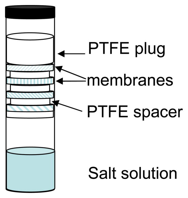
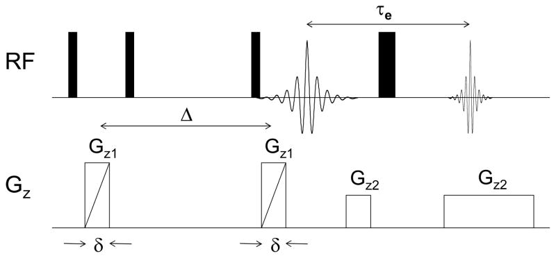
For PFGSE-NMR diffusion measurements samples of the dry membranes were cut into disks 4 mm in diameter and allowed to absorb water in a chamber maintained at constant RH until reaching equilibrium. The RH was controlled by exposure to a saturated salt solution as described previously. Once equilibrated, the membranes were stacked and sealed in a 5-mm NMR sample tube, with Teflon disks 3.5 mm in diameter and 1 mm thick serving as vertical partitions between different membranes. A 2 cm long glass insert half-filled with the same saturated salt solution used to equilibrate the membranes was placed below the stack to ensure a constant RH during the NMR experiments. Teflon slices were placed between the insert and the membranes to avoid capillary creep and contamination of the samples. The sample configuration is depicted in Figure 1. This relatively novel arrangement permits simultaneous evaluation of several membranes at once while ensuring that they all experience the same RH environment. [34] 1H NMR imaging experiments were performed on a Chemagnetics system with a 7.2 T vertical wide bore magnet and a Nalorac z-spec single-axis gradient probe. The diffusion-weighted imaging pulse sequence illustrated in Figure 2 proved to be reliable. A stimulated echo (STE) block was used to encode diffusive displacements, and an image was obtained with a frequency-encoding gradient during acquisition of the spin echo generated by the π pulse. Frequency-encoding gradients were usually 14 G/cm. Typical parameters at 25°C were Gz1 = 7–109 G/cm, incremented in 15 steps, δ = 3 msec, and Δ = 20 msec, τe = 5 msec, and eddy current delays of 2 msec following the gradient pulses. To correct for variations in Gz1 across the sample, a map of the relative gradient amplitude at different positions along the gradient-coil axis was generated using the diffusion-weighted imaging pulse sequence and a plug of doped water with known diffusivity at 25°C of Dt = 2.3×10⁻⁵ cm2s−1. The actual gradient was calculated from the nominal values, G*, of the applied gradient and the measured diffusivity, D*(z), as Gt(z) = G*D*(z)/Dt. The nominal position z was defined with respect to the center z0 of the gradient field as z −z0 = (1/γ)(δω (z)/δG*), where δω(z) is the change in resonant frequency at nominal position z with an increase δG* in the nominal gradient. During experiments with the stacked membranes, the nominal positions corresponding to peaks in the imaging spectrum of a sample were determined by the same approach employed with the water calibration sample. Once positions were known, correction factors were obtained from the gradient map by interpolation. From estimates of the uncertainties associated with the above procedure coupled with uncertainties in the standard PGSE method, as well as a limited number of repeated experiments, it was determined that the data is subject to a ± 5% variation.
Fig. 1.
Sample configuration for PFGSE-NMR diffusion measurements.
Fig. 2.
Diffusion-weighted single-axis NMR imaging sequence.
2.2.4 MEA testing
Fuel cell tests were performed by using a compact system (850C, Scribner Associates Inc.) connected to a 5 cm2 cell fixture. The active surface of the used electrodes (E-Tek, 0.5 mg Pt cm−2) was brushed with a Nafion solution (ca. 0.4 mg dry Nafion cm−2). The membrane-electrode assembly, MEA, was realized by hot pressing the given membrane between two electrodes at 120 °C and 2 atm for 7 minutes. The cell was fed with H2 and air according to current-dependent mass flow rates, by using an excess of the reactants amount required by the Faraday’s law. Namely, the excess were: for the anode 1.4 and for the cathode 3.3 times those required from the reactions stoichiometry.
The humidification of the cell was accomplished by bubbling the fed gases through stainless steel cylinders incorporated in the compact system and containing distilled water. Reactant gas pressure in the cell could be varied by a back-pressure control module. The temperature of the humidifiers, as well as that of the cell, was properly set to achieve the desired relative humidity. The relative humidity values were calculated on the basis of water vapor pressure at cell temperature and at humidifier temperature [35]. Before recording polarization curves as a function of relative humidity, the cell was conditioned by fast current scans for two days at increasing temperature (from 30 to 99 °C) under full humidification.
3. Result and Discussion
3.1 Characterization of ZrO2 and SZrO2 samples
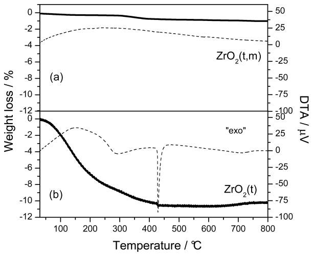
Two Zirconia samples were prepared through a sol-gel procedure followed by two different thermal treatments. Fig. 3 shows their TG-DTA profiles. The sample heated to 700°C for 6 hours, ZrO2(t,m), showed no weight losses in the whole range of temperature investigated (fig. 3a), while for the sample heated to 110°C for 15 hours, ZrO2(t), two weight losses were observed (fig. 3b). The first one (8 wt. %), corresponding to a large endothermic peak in the DTA curve, was centered at a 140 °C, and it is due to desorption of water and propanol occluded in the gel. The second weight loss (2 wt. %) was associated with a DTA exothermic peak centred at 290 °C and can be related to the loss of residual organic groups and to the decomposition of zirconium hydroxide crystals, Zr(OH)4, into ZrO2 [36]. The exothermal peak occurred at 430 °C and is attributed to the partial transformation from the amorphous quasi-tetragonal phase to monoclinic phase.
Fig. 3.
The TG (solid line) and DTA (dashed line) responses of ZrO2 precursor calcined at 700°C for 6 hours (a) and dried at 110°C for 15hours and (b).
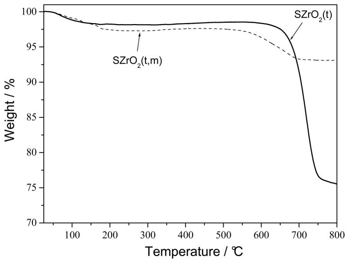
Fig. 4 shows the thermogravimetric (TG) response of the sulfated-ZrO2 samples. Both SZrO2 (t,m) and SZrO2 (t) samples showed a weight loss of about 2–3% at temperatures lower than 200 °C due to water evaporation. The second weight loss occurring at higher temperature, is attributed to the decomposition of SO42− bound to the surface of ZrO2, which leads to the formation of SO2. The decomposition of sulphate groups started at 550°C for SZrO2(t,m) and at 650°C for SZrO2(t) indicating a higher stability of the latter sample [31]. The higher weight loss observed for the SZrO2(t) sample (ca. 22 %) with respect to that observed for the SZrO2 (t,m) (ca. 4%) is indicative of its higher sulphate groups content.
Fig. 4.
The TG responses of SZrO2(t) (solid line) and SZrO2(t,m) (dashed line) powders.
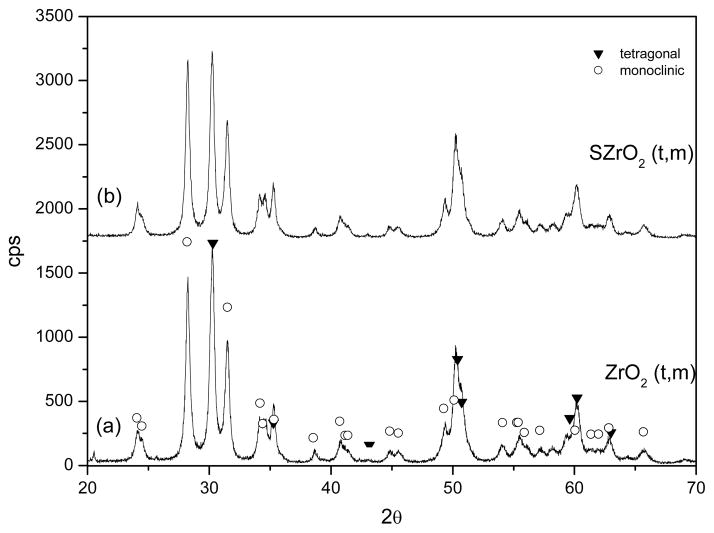
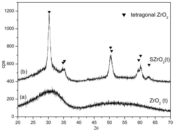
Fig. 5 and Fig. 6 display the XRD patterns of the two samples before (Fig. 5a, 6a) and after (Fig. 5b, 6b) the sulphating process. It is not surprising that the two different thermal treatments led to different phases, in fact it is well known that several factors, such as thermal treatments and the conditions for obtaining the oxide precursor, have been acknowledged to play a key role in affecting the phase of the ZrO2 [37]. The XRD patterns of the samples ZrO2(t,m) and SZrO2(t,m) show that tetragonal and monoclinic crystals coexisted before and after the sulphating procedure, see Figure 5. This finding indicates that, when sulphuric acid is added to the crystalline ZrO2 (t,m) sample, the SO42− groups bound to the oxide surface do not influence the structural phase composition. The XRD patterns of the ZrO2(t) and SZrO2(t) samples are displayed in Figure 6. XRD profile of unsulfated ZrO2(t) (Fig. 6a) shows a nearly amorphous pattern, with traces of tetragonal zirconia microcrystals as indicated by the incipient peak at 30.2 (2θ). After the sulphating process, a pure tetragonal phase was obtained (Fig. 6b). The addition of a sulphating agent to amorphous ZrO2 is expected to cause substitution of the OH− groups present on the zirconia surface by SO42− ions leading to the stabilization of the “low-temperature structure” (i.e. the tetragonal one). The thermal stability of the sulphate to zirconium bond is in fact much higher than that of the hydroxyl bridges across two Zr atoms and this delays the formation of some oxo bonds [36].
Fig. 5.
XRD patterns of the ZrO2(t) powder before (a) and after (b) the sulphating process
Fig. 6.
XRD patterns of the ZrO2(t,m) powder before (a) and after (b) the sulphating process
Figure 7 displays the SEM micrographs of SZrO2 (t,m) (Fig. 7a) and SZrO2 (t) (Fig:7b). The morphology consists of agglomerates of nanoparticles having an average diameter in the range 10–30 nm for both samples.
Fig. 7.
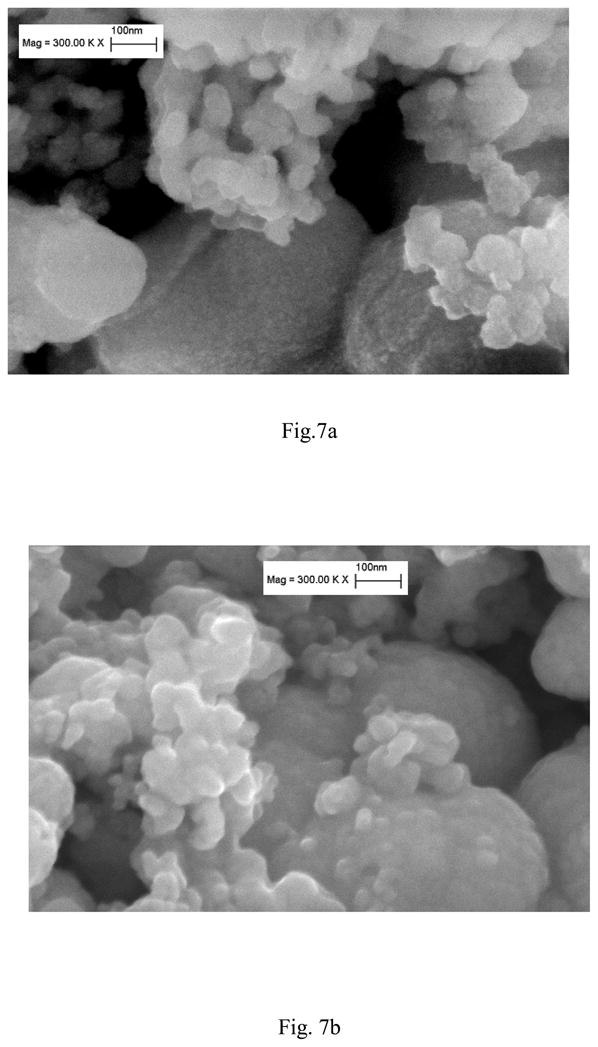
SEM images of SZrO2(t) (a) and SZrO2(t,m) (b) nano powders
3.1 Characterization of composite membranes
Two composite Nafion-based membranes containing 5 wt. % of the two different sulfated zirconia samples (i.e. N_SZrO2 (t,m) and N_SZrO2 (t)) were prepared by a casting procedure together with a reference Nafion recast membrane. The ion exchange capacity values (IEC) measured for the three samples were quite similar, around 0.89 meqg−1, indicating an active contribution of the synthesized fillers in providing free acid groups to the membrane, as expected from the proton conductivity features of the sulfated oxide itself [26].
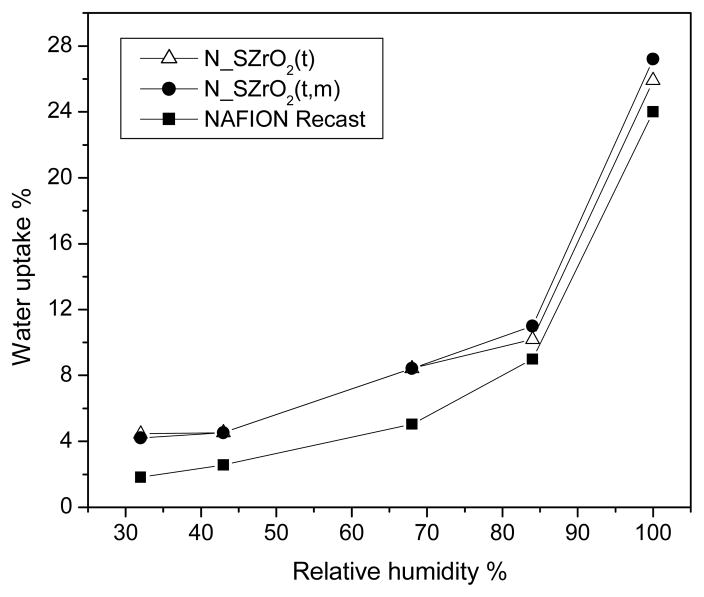
Figure 8 shows the room temperature vapour phase water uptake (WU) behaviour observed for Nafion recast and N_SZrO2 (t,m) and N_SZrO2 (t) composite membranes as a function of relative humidity (RH). The composites showed an enhanced WU when compared to Nafion in the whole range of RH investigated. The enhanced water uptake can be attributed to the hydrophilic nature of the additives within the pores of Nafion membrane [3]. This effect is particularly evident at low RH. In fact, the enhancement in WU is higher than 100% at 30% RH and only about 12.5% at 100% RH, for both composites. In any case, WU values for the two doped membranes were similar, indicating that the different amount of SO42− groups on the zirconia surface (22% and 4% for the SZrO2 (t) and SZrO2 (t,m), respectively) does not strongly influence the room temperature water uptake.
Fig. 8.
Water uptake vs. RH for nanocomposite N-SZrO2(t), N-SZrO2(t,m) and Nafion recast membranes at 25°C.
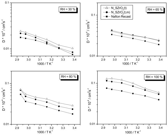
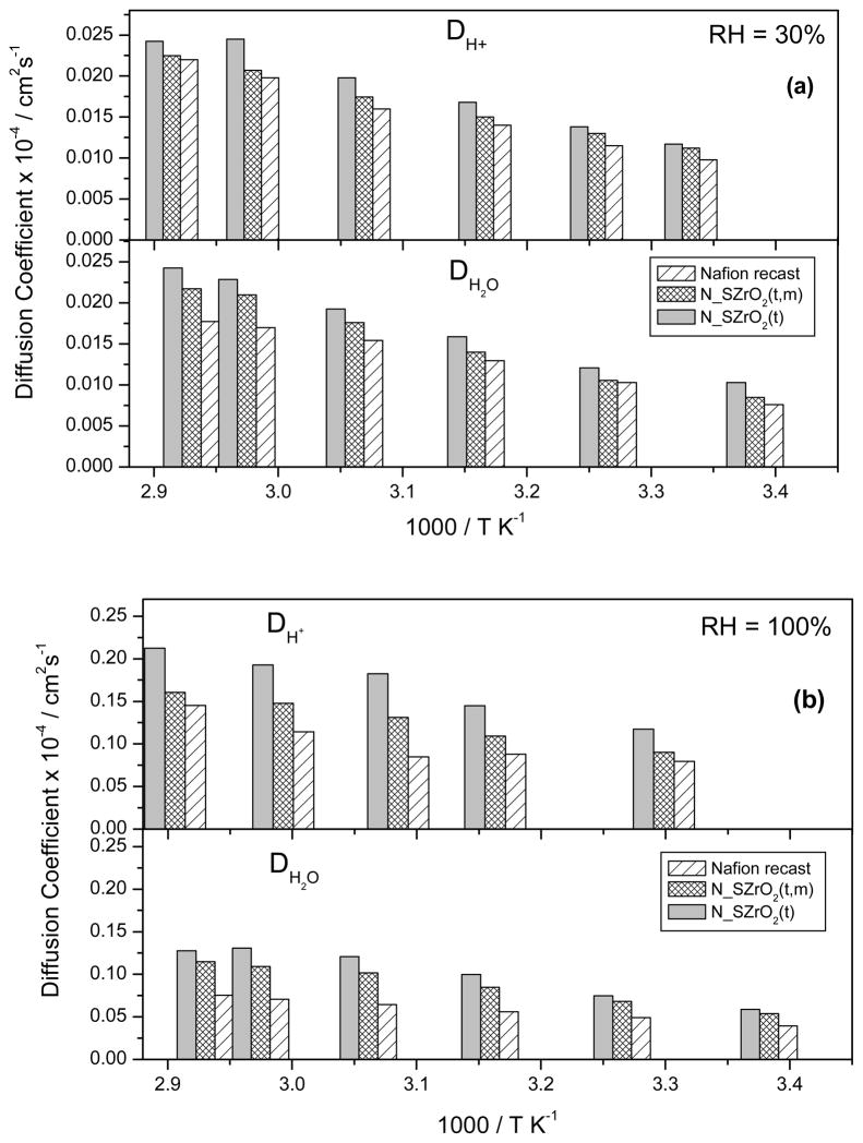
PGSE-NMR experiments provide information on the translational motion of protons in the membrane by measurement of the water self-diffusion coefficients (DH2O). By comparing the data relative to composite membranes having different amounts of sulphate groups bound to the inorganic additive the influence of surface modification on water retention and proton transport at different RH values and temperature can be evaluated. These data were then compared to those relative to Nafion recast measured under the same conditions. Fig. 9 shows the Arrhenius plots of the water self-diffusion coefficients of Nafion recast and Nafion composite membranes at different RH values. DH2O values of the composite membranes were higher than those of unfilled Nafion in all RH conditions, in agreement with WU measurements, that is, higher water mobility is closely associated with higher water content [38,39]. However, while WU values of the two composite membranes were similar, DH2O of the N_SZrO2(t) was higher than that of N_SZrO2(t,m) in the whole range of RH and T examined. Given the similar hygroscopic character of the two membranes, the higher DH2O values measured for N_SZrO2(t) cannot be a mere consequence of the extent of WU but must be due to the higher SO42− content of the SZrO2(t) filler that provided extra acid sites facilitating water diffusion [40].
Fig. 9.
Self-diffusion coefficients of water (DH2O) measured by PFGSE–NMR technique at different RH for N-SZrO2(t), N-SZrO2(t,m) and Nafion recast membranes, from 25 °C up to 80°C.
Proton conductivity (σH+) was measured by EIS and proton diffusivity (DH+) was estimated from conductivity data using the Nernst-Einstein equation:
| (Eq.4) |
where F is Faraday’s constant, R is the universal gas constant, T is the absolute temperature and C is the molar proton concentration which can be calculated from IEC and density values. DH+ and DH2O values at 30% and 100% RH were evaluated as a function of temperature and they are shown in Figure 10a and 10b, respectively. The justification for their comparison is based on the simplified assumption that the average H+ diffusion coefficient is approximately that of the water molecules on which they reside (even for a very short time on the NMR timescale), as in the case of an H3O+ ion. Though Eq.4’s region of applicability is for much lower ion concentrations than in the present case, it still offers a convenient means to assess possible changes in conductivity mechanism. For all samples the mobility of protonic charge carriers and the water self-diffusion coefficients were similar at low RH, differing as the RH, hence water content, increased. At low RH values (Fig. 10a), the difference between DH+ and DH2O values was negligible, whereas at higher RH values (Fig. 10b) such difference became larger. It is known that the difference between DH+ and DH2O at high RH is due to the intermolecular proton transfer related to the mobility of protonic charge carriers (Grotthus mechanism) [41,42], indicating that transport of H+ by Grotthus hopping becomes increasingly significant at high water contents, whereas it resulted to be negligible at low water contents [43]. Moreover, composite membranes showed enhanced DH+ and DH2O values than those of unfilled Nafion. The increase of both DH2O and DH+ of the N_SZrO2 respect to pure Nafion is the combined results of the enhanced water uptake as well as of the acidity. The sulfated groups on the Zirconia surface introduce both acid Lewis sites and Bronsted acid sites, according to model proposed by Arata et al. [43, 26], these sites facilitating both water self diffusion coefficient and ionic mobility. It is noteworthy that the increased proton mobility at low RH values for N_SZrO2 composites is a key point for their use in real fuel cell devices as electrolytes.
Fig. 10.
Comparison between proton diffusion coefficients (DH+) derived by EIS and the Self-diffusion coefficients of water (DH2O) measured by NMR for N-SZrO2(t), N-SZrO2(t,m) and Nafion recast membranes at 30% RH (a) and 100% RH (b).
It is generally acknowledged that the performance of a PEMFC strongly depends on operative temperature, pressure and relative humidity. It is also well known that low RH values allow to simplify the whole system and offer significant cost savings. For these reasons we evaluated the influence of relative humidity on the PEMFC performances at a constant reference temperature (i.e. 70 °C). Due to its attracting properties in terms of proton mobility and thermal stability, N_SZrO2(t) membrane was selected as electrolyte separator and tested in a H2-air fuel cell.
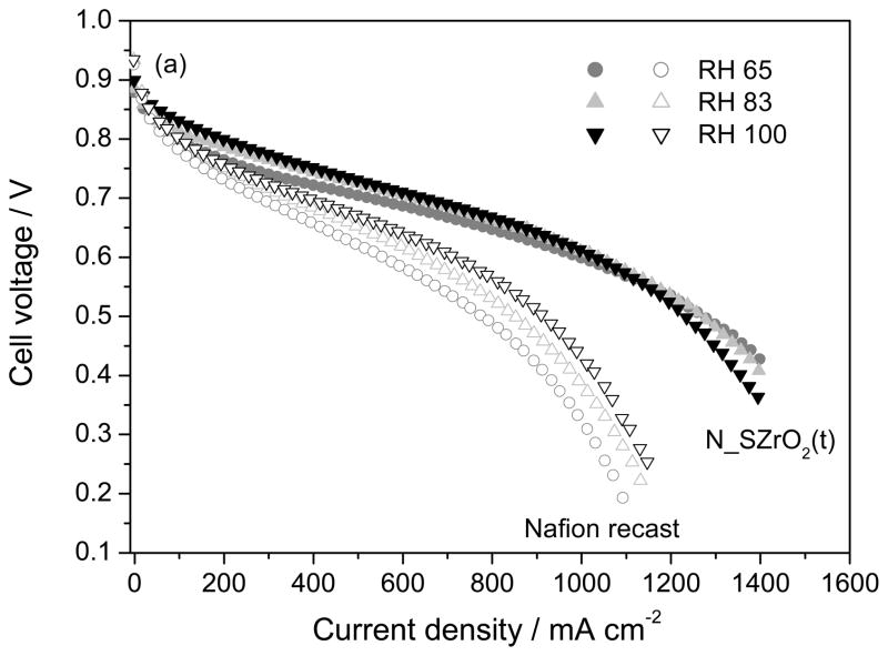
Figure 11 shows the I–V curves obtained with N_SZrO2 (t) and unfilled Nafion membranes at 70°C and at different RH values, ranging from 65% to 100%. While the performance of the Nafion recast membrane was substantially affected by the humidity level, the polarization curves relative to the composite membrane showed only a small improvement with increasing RH from 65 to 100 %. Moreover, the polarization curves of the cells based on the composite membrane exhibited better characteristics than those based on Nafion recast in the same conditions: at 0.6V and RH 83%, the current density for unfilled Nafion was 680 mAcm−2, whereas for the composite 1015 mAcm−2 were achieved. Moreover, it is interesting to note that in the low current density region the performance of Nafion recast and composite membranes were similar, whereas in the intermediate-high current density region the differences between the two samples increased. This behaviour can be ascribed to a low ohmic resistance and to an improved ion transport through the N_SZrO2 membrane with respect to unfilled Nafion, according to NMR and EIS data.
Fig. 11.
Polarization curves at 65, 83 and 100% RH values using MEAs fabricated with Nafion recast and N_SZrO2 (t). P(H2-air) = 2atm, Tcell = 70°C
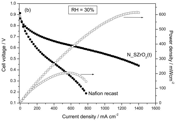
Fig 12 shows the polarization and power density curves of N_SZrO2 (t) and unfilled Nafion membranes at 70°C and at lower RH value, i.e. 30%. Again, the composite performed better than Nafion but the difference between the two samples in terms of current (and power) density is higher with respect to the higher RH cases shown in Figure 11, in fact at 0.6V the current density for unfilled Nafion was only 200 mAcm−2, whereas for the composite 930 mAcm−2 were achieved. This enhancement corresponds to a 200% increase of in terms of power density. Furthermore, differently from the high RH case (Figure 11), at lower RH the N_SZrO2(t) membrane showed a much higher performance than that of Nafion both in the activation and in the ohmic-diffusion control region. This behavior can be ascribed to an enhanced membrane-electrode interface contact, probably due to the absence of ionomer shrinkage [29], as well as to a lower mass-transport limitation. These findings indicate that the filler effect is more evident at low RH.
Fig. 12.
The Polarization and Power density curves at 30% RH using MEAs fabricated with Nafion recast and N_SZrO2 (t) P(H2-air) = 2atm, T cell = 70°C
4. Conclusions
Synthesis parameters, adopted during the preparation of sulfated zirconia particles, were found to play a key role in the properties of the resulting powders. Crystallographic form, as well as sulphate group concentration, was strongly influenced by the thermal treatments chosen for the formation of the oxide precursor. In any case, hydro-thermally stable compounds were obtained, being the sulphate groups tightly bonded to Zr on a heat-treated SZrO2 surface.
The positive effect of the synthesized sulfated zirconia on Nafion properties was demonstrated. The superacidic inorganic compound promoted higher hydration level in the composite membranes with respect to an additive-free Nafion membrane, as revealed by water uptake measurements.
The presence of the inorganic compound resulted also in higher water diffusion coefficients for the doped membranes over a wide range of temperature (i.e. 25 – 90 °C) and external relative humidity (i.e. 30 – 100 %). In particular, SZrO2 (t), by virtue of its greater amount of surface SO42−, allowed the best water diffusivity among those related to the samples here investigated.
Proton conductivity, as derived from impedance spectroscopy measurements, was used to calculate proton diffusion coefficients using the Nernst-Einstein equation. For all samples, DH+ values were much higher than water self-diffusion coefficients at 100 % RH in the whole range of explored temperatures, while there were no big differences between DH+ and DH2O at 30 % RH. This reveals that the intermolecular proton transfer, related to the mobility of protonic charge carriers, becomes significant at high water contents. In any case the composite membranes exhibited an improved proton and water diffusivity with respect to undoped Nafion, also at very low hydration level. SZrO2(t)/Nafion membrane was used as electrolyte separator in a fuel cell working at 70 °C in the range 30 – 100 % RH. Interestingly, the performances of the cell, in terms of current and power delivered, were almost independent on the relative humidity level. In comparison with an unmodified Nafion-based cell, the greatest enhancement was found by using the composite membrane electrolyte at 30 % RH. This result is very attractive in view of potential application in fuel cells for transportation. Here, in fact, the cell stack must be able to perform without external humidification, which is a source of additional cost and complexity to the system. A further and more detailed analysis of the cell performances, using the synthesized sulfated zirconia particles as both membrane and electrode additives, is currently being developed in our laboratories, by exploring a wide range of operating conditions.
Acknowledgments
Part of this work has been performed in the framework of the NUME Project, titled “ Development of composite proton membranes and of innovative electrode configurations for polymer electrolyte membrane fuel cells” supported by the Italian Ministry of University and Research, MIUR, program FISR 2001. The financial support of the Ministry for Foreign Affairs (Italy-Quebec Joint Lab for Advanced Nanostructured Materials for Energy, Catalysis and Biomedical Applications) is also gratefully acknowledged. FIRB, Project “RINNOVA” titled Innovative electrochemical technologies for energy storage from renewable sources, sponsored by the Italian Ministry of University and Research. The work at Hunter College was supported by a grant from the U.S. Air Force Office of Scientific Research the National Institutes of Health through the RCMI (RR003037) MBRS-RISE programs.
References
- 1.Watanabe M, Uchida H, Seki Y, Emori M, Stonehart P. J Electrochem Soc. 1996;143:3847–3852. [Google Scholar]
- 2.Adjemian KT, Lee SJ, Srinivasan S, Benziger J, Bocarsly AB. J Electrochem Soc. 2002;149:A256–A261. [Google Scholar]
- 3.Jalani NH, Dunn K, Datta R. Electroch Acta. 2005;51:553–560. [Google Scholar]
- 4.Savadogo O. J Power Sources. 2004;127:135–161. [Google Scholar]
- 5.Herring AM. Polymer Rev. 2006;46:245. [Google Scholar]
- 6.Sahu AK, Selvarani G, Pitchumani S, Sridhar P, Shukla AK. J Electrochem Soc. 2007;154:B123. [Google Scholar]
- 7.Baglio V, Di Blasi A, Aricò AS, Antonucci V, Antonucci PL, Serraino Fiory F, Licoccia S, Traversa E. J New Mater Electrochem Syst. 2004;7:275. [Google Scholar]
- 8.Chalkova E, Fedkin MV, Wesolowski DJ, Lvov S. J Electrochem Soc. 2005;152:A1742. [Google Scholar]
- 9.Saccà A, Carbone A, Passalacqua E, D’Epifanio A, Licoccia S, Traversa E, Sala E, Traini F, Ornelas R. Journal of Power Sources. 2005;152:16–21. [Google Scholar]
- 10.Licoccia S, Traversa E. J Power Sources. 2006;159:12. [Google Scholar]
- 11.Watanabe M. 5.472.799. US Patent. 1995
- 12.Hara S, Takano S, Miyayama M. J Phys Chem B. 2004;108:5634. [Google Scholar]
- 13.Abbaraju RR, Dasgupta N, Virkar AV. J Electrochem Soc. 2008;155:B1307–B1313. [Google Scholar]
- 14.Mecheri B, D’Epifanio A, Traversa E, Licoccia S. Journal of Power Sources. 2008;178:554–560. [Google Scholar]
- 15.Mecheri B, D’Epifanio A, Pisani L, Chen F, Traversa E, Weise FC, Greenbaum S, Licoccia’ S. Fuel Cells. 2009 in press. [Google Scholar]
- 16.Costamagna P, Yang C, Bocarsly AB, Srinivasa S. Electrochim Acta. 2002;47:1023–1033. [Google Scholar]
- 17.Alberti G, Casciola M, Capitani D, Donnadio A, Narducci R, Pica M, Sganappa M. Electrochim Acta. 2007;52:8125–8132. [Google Scholar]
- 18.Malhotra S, Datta R. J Electrochem Soc. 1997;144:L23. [Google Scholar]
- 19.Rao PM, Wolfson A, Kababya S, Vega S, Landau MV. J Catal. 2005;232:210. [Google Scholar]
- 20.Ramani V, Kunz HR, Fenton JM. Electrochim Acta. 2005;50:1181. [Google Scholar]
- 21.Lopez-Salinas E, Hernandez-Cortez JG, Cortez M, Navarrete J, Yanos M, Vazquez A, Armendaris H, Lopez T. Appl Catal A. 1998;175:43. [Google Scholar]
- 22.Saccà A, Carbone A, Pedicini R, Marrony M, Barrera R, Elomaa M, Passalacqua E. Fuel Cells. 2008;8:225–235. [Google Scholar]
- 23.Thampan TM, Jalani NH, Choi P, Datta R. J Electrochem Soc. 2005;152:A316–A325. [Google Scholar]
- 24.Misono M, Okuhara T, Mizuno N. In: Successful Design of Catalysts. Inui T, editor. Vol. 267. Elsevier; Amsterdam: 1988. [Google Scholar]
- 25.Yadav GD, Nair JJ. Microporous Mesoporous Mater. 1999;33:1. [Google Scholar]
- 26.Hara S, Miyayama M. Sol State-Ionics. 2004;168:111–116. [Google Scholar]
- 27.Li C, Li M. J Raman Spectrosc. 2002;33:301–308. [Google Scholar]
- 28.Navarra MA, Croce F, Scrosati B. J Mater Chem. 2007;17:3210–3215. [Google Scholar]
- 29.Navarra MA, Abbati C, Scrosati B. J Power Sources. 2008;183:109–113. [Google Scholar]
- 30.Navarra MA, Abbati C, Croce F, Scrosati B. Fuel Cells. doi: 10.1002/fuce.200800066. [DOI] [Google Scholar]
- 31.Li Binghui, Gonzalez Richard D. Ind Eng Chem Res. 1996;35:3141–3148. [Google Scholar]
- 32.Licoccia S, Polini R, D’Ottavi Cadia, Fiory F Serraino, Di Vona M Luisa, Traversa E. Journal of Nanoscience and Nanotechnology. 2005;5:592–595. doi: 10.1166/jnn.2005.072. [DOI] [PubMed] [Google Scholar]
- 33.Arata K. Appl Catal A. 1996;146:3–32. [Google Scholar]
- 34.Fernicola A, Weise FC, Greenbaum SG, Kagimoto J, Scrosati B, Soleto A. J Electrochem Soc. 2009;156:A514–A520. doi: 10.1149/1.3122885. [DOI] [PMC free article] [PubMed] [Google Scholar]
- 35.Adjemian KT, Dominey R, Krishnan L, Ota H, Majsztrik P, Zhang T, Mann J, Kirby B, Gatto L, Velo-Simpson M, Leahy J, Srinivasan S, Benziger JB, Bocarsly AB. Chem Mater. 2006;18:2238. [Google Scholar]
- 36.Wang JA, Valenzuela MA, Salmones J, Vázquez A, Garcia-Ruiz A, Bokhimi X. Catalysis Today. 2001;68:21–30. [Google Scholar]
- 37.Widoniak J, Eiden-Assmann S, Maret G. J Inorg Chem. 2005:3149–3155. [Google Scholar]
- 38.Nicotera I, Zhang T, Bocarsly A, Greenbaum S. Journal of the Electrochemical Society. 2007;154(5):B466–B473. doi: 10.1149/1.2779962. [DOI] [PMC free article] [PubMed] [Google Scholar]
- 39.Zawodzinski Thomas A, Jr, Neeman Michal, Sillerud Laurel, Gottesfeld Shimshon. J Phys Chem. 1991;95:6040–6044. [Google Scholar]
- 40.Ren S, Sun G, Li C, Song S, Xin Q, Yang X. Journal of Power Sources. 2006;157:724–726. [Google Scholar]
- 41.Agmon N. Chem Phys Lett. 1995;244:456. [Google Scholar]
- 42.Kreuer KD. Chem Mater. 1996;8:610. [Google Scholar]
- 43.Arata K, Hino M. Appl Catal A. 1990;59:197. [Google Scholar]


