Abstract
Purpose:
To compare the data quality and ease of use of four endorectal-coil probe setups for prostate MRI.
Materials and Methods:
Four endorectal-coil probe setups were compared: 1) air-inflated probe; 2) perfluorocarbon (PFC)-inflated probe; 3) rigid, smaller prototype coil; and 4) rigid, smaller coil designed for biopsying the prostate. Signal-to-noise ratio (SNR), positioning, shimming, MRI motion artifact, and MR spectroscopic imaging (MRSI) spectral quality were assessed.
Results:
Rigid coils provided approximately 2.5-fold higher SNR than inflatable coils near the peripheral zone midline. The biopsy probe sensitivity decreased dramatically by the apex. The rigid probes, as compared to the inflatable probes, took longer to place (10 ± 2 vs. 7 ± 2 minutes, P < 0.0002), tended to be placed too superiorly, required repositioning more often (73% vs. 20%, P < 0.003), and had higher motion artifacts (P < 0.001). Shimming time was least for the PFC-inflated probe (2 ± 0.5 minutes, P < 0.05). The air-inflated probe produced larger linewidths (P < 0.01) and tended to have longer shim times (7 ± 4 minutes) and poorer spectral quality.
Conclusion:
The inflatable coil is a good clinical choice due to ease of use, good coverage, and low motion artifacts. PFC-inflation is recommended as it provided higher quality data than air-inflation. The rigid, smaller probes have higher SNR and produce less tissue distortion and may be preferred for certain applications.
Keywords: endorectal coil, prostate, perfluorocarbon, rigid coil, magnetic resonance spectroscopic imaging
Endorectal Coils can provide dramatically improved (~10-fold) signal-to-noise ratio (SNR) and spatial resolution for MRI of the prostate as compared to phased-array coils (1,2). This is particularly important for functional imaging studies such as spectroscopic imaging, dynamic contrast-enhanced MRI, and diffusion-weighted MRI. Commonly, a coil placed in the rectum on an air-inflated balloon is used (3,4). This design by Medrad, Inc. (Indianola, PA, USA) has been used extensively and has been shown to provide increased SNR over pelvic phased-array coils (2). While this coil provides an increase in SNR, it can cause tissue distortion (5). Additionally, the common implementation of this inflated coil is to fill the probe with air. This air in close proximity to the tissue of interest (peripheral zone of the prostate) causes magnetic susceptibility artifacts (6-8). Alternative approaches to this setup have been shown to improve the MRI quality. These include inflation with an alternative substance, such as perfluorocarbon (7,9) or barium (8), and the design of a rigid, noninflatable endorectal probe (6).
While these alternative approaches have been investigated, only some aspects of their performance have been evaluated. The different advantages and disadvantages of different endorectal-coil probe setups have not been investigated. Therefore, the aim of this study is to evaluate the performance and ease of use of four endorectal-coil probe setups: 1) an air-filled inflatable probe; 2) a perfluorocarbon (PFC)-filled inflatable probe; 3) a prototype rigid coil; and 4) a rigid coil designed for biopsying the prostate.
MATERIALS AND METHODS
Endorectal-Coil Probe Setups
The four endorectal-coil probe setups evaluated in this study were as follows: 1) a Medrad balloon-inflatable prostate coil, filled with air (“air-inflated”); 2) a Medrad balloon-inflatable prostate coil filled with FC-77 FLUORINERT, a PFC compound (3M, St. Paul, MN, USA) (“PFC-inflated”) (9), 3) a USA Instruments (USAI) (Aurora, OH, USA) prototype rigid coil, similar to the one by deSouza et al. (6) (“nonbiopsy rigid”); and 4) a GE Medical Systems (GE Medical Systems, Milwaukee, WI, USA) rigid coil designed for MR-guided biopsies, similar to one designed by Watkins et al (10) (“biopsy-rigid”). The Medrad inflatable probe had a length (in the approximately superior/inferior [S/I] direction) of 79 mm and a width (in the right/left [R/L] direction) of 44 mm. The two rigid probes were smaller: the rigid coil by USAI was 65 mm S/I and 23 mm R/L, and the biopsy probe coil was 54 mm S/I and 21 mm R/L.
Phantoms and Subjects
For each coil, a theoretical reception profile was modeled via computer simulation based upon its specific geometry (11). MR images and spectra were acquired from a phantom for each probe and from untreated prostate cancer patients for each probe setup. Numbers of subjects and their demographics for each probe setup are listed in Table 1, indicating there were no significant differences in age or Gleason score among the groups studied. Written informed consent was obtained from all subjects following a protocol approved by the Committee on Human Research at our institution.
Table 1.
Subject Demographics
| Probe setup | Number with a positive biopsy/total |
Age (years)a |
Gleason scorea |
|---|---|---|---|
| Air-inflated | 9/10 | 63 ± 8 (63) | 6.8 ± 0.7 (7) |
| PFC-inflated | 8/10 | 64 ± 8 (65) | 5.8 ± 2.2 (6) |
| Nonbiopsy rigid | 8/10 | 61 ± 9 (58) | 4.9 ± 2.8 (6) |
| Biopsy-rigid | 4/5 | 60 ± 13 (64) | 6.5 ± 1.9 (7) |
Mean ± standard deviation, median in parentheses.
MRI
Scans were performed using one of the endorectal probes and a pelvic phased array on a GE 1.5T Signa Imager. The USAI pelvic phased-array was used with the USAI prototype nonbiopsy-rigid probe. The GE four-channel, pelvic phased array was used for the remaining three probe setups. The USAI pelvic phased array was different in geometry than the GE pelvic phased array—it had a longer S/I coverage. However, in both cases the endorectal probe provided the majority of the signal in the prostate (on the order of 90%), with little difference between the contributions of the USAI pelvic phased array vs. the GE pelvic phased array. MRI included axial T1-weighted and fast spin-echo T2-weighted images. The T2-weighted images were acquired with a fast spin-echo sequence with: TR = 6000 msec, effective TE = 100 msec, slice thickness = 3 mm, field of view (FOV) = 14 cm, and matrix size = 256 × 256. The 3D MR spectroscopic imaging (MRSI) data were acquired using a point-resolved spectroscopy (PRESS) sequence incorporating dual band spectral spatial pulses to limit the amount of water and lipid in the spectra (12). Very selective spatial suppression pulses were applied in three dimensions to the outside of the PRESS volume to reduce spectral contamination (13). A 16 × 8 × 8 matrix was used to acquire 7 × 7 × 7 mm3 voxels (0.34 cc) with TR/TE = 1000 msec/130 msec. For the biopsy-rigid probes, the spatial resolution was 0.125 mm3. A spectral bandwidth of 1250 Hz was used with 512 data points. The images and spectra were then transferred offline to Sun SPARC workstations (Sun Microsystems, Palo Alto, CA, USA) for processing.
Data Analyses
MR Processing
The T2-weighted images of the prostate were intensity-corrected for the inhomogeneous reception profile of the endorectal coil plus pelvic phased-array coil combination. The theoretical reception profiles of the coils were modeled based upon their geometry and the Biot-Savart law, as described previously (11,14). These modeled profiles were aligned to the image data set and combined. Acquired images were divided by these profiles (11,14). For 3D MRSI analyses, each spectrum was Fourier transformed, frequency-, phase-, and baseline-corrected, and peaks representing creatine and citrate were integrated, using algorithms well established at our institution (15,16). Spectra for the inflated probes were constructed at a resolution of 0.086 cc, which corresponds to a doubling of resolution in two dimensions and results in the final resolution more closely matching that of the rigid probes (0.125 cc).
Coil Sensitivities
The theoretical reception profiles of the coils were modeled via computer simulation based upon their specific geometries and the Biot-Savart law as described previously (11). On axial images, distances from the coil to the rectal wall, from the rectal wall to the start and end of the peripheral zone, and to the most anterior part of the central gland were measured. A circular region of interest (ROI) was drawn in phantoms at the median distance of the peripheral zone from the given coil. SNR measurements were made for these sensitive regions of the coils vs. a background noise measurement, which were then normalized to the maximum of the inflatable endorectal probe. These relative SNR measurements were applied to the theoretical coil reception profiles.
MR Acquisition and Positioning Issues
The time required for proper positioning of the endorectal coil probes was recorded. For this study, the nonbiopsy-rigid probe was placed without coil positioning devices more recently developed to aid positioning and reduce motion. After acquisition of the scout image, the images were viewed by an experienced prostate MR spectroscopist. If the position of the coil was not sufficiently close to and aligned with the prostate in both the sagittal and axial planes, the probe was moved and the subject was rescanned. The magnetic field was shimmed before the MRSI acquisition. The time required for manual shimming and the values of the x, y, and z gradient shims were recorded after autoshimming and after subsequent manual shimming.
MR Data Quality
An experienced (15 years) spectroscopist evaluated the T2-weighted images of patient studies for motion artifact using a 1–5 scaling system, with 1 having the least and 5 having the greatest artifact. Additionally, this spectroscopist scored the datasets for spectral quality on an 1–5 scale (1 = excellent and 5 = poor) based on SNR, spectral resolution, and water and lipid suppression. The motion artifact and spectral quality scores were compared among the four endorectal-coil probe setups. Additionally, line-widths of water for the spectra within the PRESS-selected region were also measured and compared among the four endorectal-coil probe setups.
Statistics
Statistical analyses were performed using Excel (Microsoft, Seattle, WA, USA) and JMP V5.1 software (SAS Institute, Cary, NC, USA). Descriptive statistics were calculated and likelihood ratio chi-squared tests of contingency analyses were performed to compare the scores with the coil types. The Fisher's exact test was used to compare the incidence of coil repositioning between the rigid probes and the inflated probes. t-Tests were used to compare times and linewidths between the rigid and inflatable probes. A Bonferroni correction for multiple comparisons was applied when applicable. A P value of <0.05 was used for statistical significance.
RESULTS
Coil Sensitivities
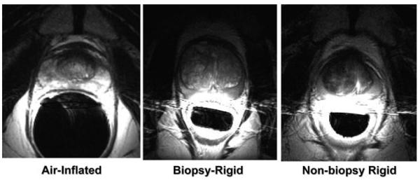
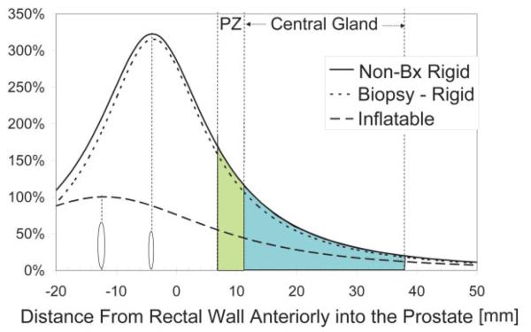
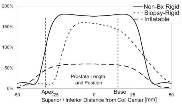
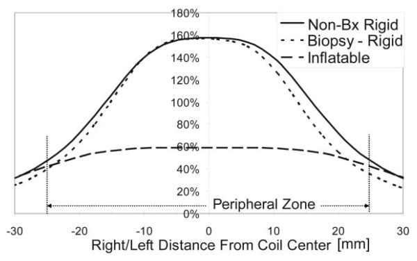
Example axial prostate images acquired with the three different coils are shown in Fig. 1. These images are shown as acquired, i.e., not corrected for the reception profiles of the coils. With these images, a more dramatic lateral decrease in sensitivity is noted with the rigid coils as compared to the inflatable coil. Line profiles through the prostate for each of the coils are shown in Figs. 2-4. SNR was significantly higher for the rigid probe datasets for most of the peripheral zone regions. In the center of the coil, at the distance of the peripheral zone, phantom studies showed the nonbiopsy-rigid probe to have 260% and the biopsy-rigid probe to have 240% of the inflatable probe SNR. Laterally in the prostate, the smaller rigid probes demonstrated lower SNR than the inflatable probe. Also, the SNR of the biopsy probe dropped dramatically by the apex. The rigid probes were not only smaller in size, but the coil elements were positioned closer to the peripheral zone than the inflated balloon coils in which the air space distanced the coil wires further from the rectal wall. However, the inflated balloon also acted to compress the rectal wall, decreasing the distance to the peripheral zone. Overall, the inflated coil probe remained further from the peripheral zone of the prostate.
Figure 1.
Axial images of the prostate taken with the different probes. a: Air-inflated probe. b: Biopsy-rigid probe. c: Nonbiopsy-rigid probe.
Figure 2.
Anterior/posterior SNR into the prostate, at the midline, relative to the maximum with the inflatable coil. Locations of the coils and the peripheral zone (PZ) and central gland relative to the rectal wall are shown. Locations of the coils are marked with ovals. [Color figure can be viewed in the online issue, which is available at http://www.interscience.wiley.com.]
Figure 4.
S/I SNR along the prostate, at the peripheral zone, relative to the maximum with the inflatable coil. Typical size and position of the prostate is indicated. The biopsy coil loses SNR at the apex.
MR Acquisition Times and Issues
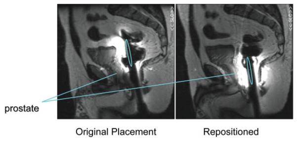
The time required for placement was longer for the rigid probes (10 ± 2 minutes) vs. the inflatable probes (7 ± 2 minutes) (P < 0.0002, t-test). This was likely due to the fact that the inflatable coil seats itself on the prostate when inflated and does not move as the patient is transferred from his side to his back. Additionally, the rigid probes tended to be placed too superiorly (see Figs. 4 and 5). After acquiring the scout image to assess proper coil position, the rigid probes required repositioning for more cases (73%) than the inflatable coils (20%) (P < 0.003, Fisher's exact test). The time needed to inflate the balloon coil with PFC vs. air was insignificantly increased (<1 minute), and removal of the PFC took slightly longer than air, on the order of several seconds.
Figure 5.
Positioning error common for rigid probes. Sagittal images after original probe placement (left) and after the probe was repositioned (right). The location of the coils is indicated by the ovals. [Color figure can be viewed in the online issue, which is available at http://www.interscience.wiley.com.]
The time required for manual shimming was slightly less for rigid probes (4.5 ± 3 minutes) vs. the air-inflated probe (7 ± 4 minutes) (P = not significant), but least for the PFC inflated probe (2 ± 0.5 minutes) (P < 0.04, t-test with Bonferroni correction vs. rigid and airinflated probes). Also, the autoshim values were farthest from the subsequent manual touch-up shim values for the air-inflated probe, but this did not reach statistical significance.
MR Data Quality
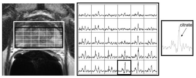
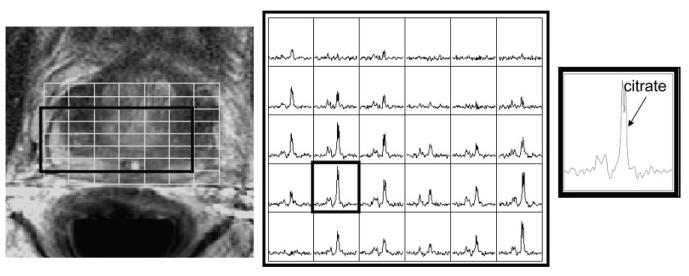
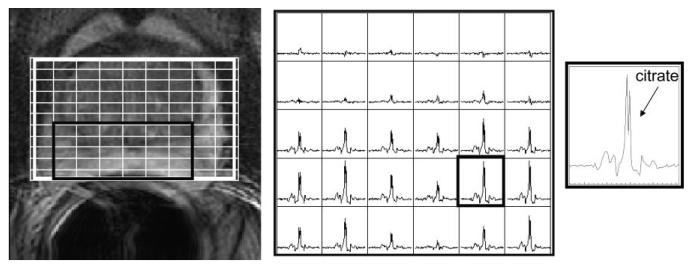
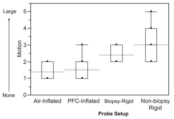
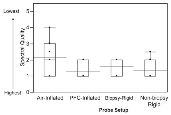
Example MR images and spectra are shown in Figs. 1, 6, 7, and 8. Note that the rigid probe produced higher SNR spectra than the inflatable probe but also had larger motion artifact in the images. Also, note that the PFC inflated probe spectra were best at resolving the doublet of citrate (the peaks are separated by about 3 Hz at 1.5T). The mean motion score for images acquired using the rigid probes (2.4 ± 0.5 (biopsy-rigid) and 3.0 ± 1.0 (nonbiopsy rigid)) was greater than for the inflatable probe (1.4 ± 0.5 (air-inflated) and 1.5 ± 0.7 (PFC-inflated)) (P < 0.001, likelihood ratio chi-squared tests of contingency analyses) (Fig. 9). The mean partially suppressed water linewidth within the PRESS selection region was significantly larger for the air-inflated probes (6.6 ± 0.9 Hz) vs. the rigid (5.1 ± 0.8 Hz) and the PFC-inflated (5.4 ± 0.7 Hz) probes (P < 0.01, multiple t-tests with Bonferroni correction). Accordingly, the spectral quality score was poorest for the inflatable probe filled with air (2.2 ± 1.0) vs. the group of the remaining probes (P < 0.05, likelihood ratio chi-squared tests of contingency analyses, no analysis or correction for multiple comparisons). These remaining probes were not significantly different, with spectral quality scores of 1.3 ± 0.5 (the inflatable probe filled with PFC), 1.4 ± 0.6 (nonbiopsy-rigid), and 1.6 ± 0.5 (biopsy-rigid) (Fig. 10).
Figure 6.
Example MR images and MR spectra for the air-inflated endorectal probe. T2-weighted image with MRSI grid (left), an array of spectra from the grid shown in the image (middle), and a spectrum from the outlined voxel in the array (right).
Figure 7.
Example MR images and MR spectra for the nonbiopsy-rigid endorectal probe. T2-weighted image with MRSI grid (left), an array of spectra from the grid shown in the image (middle), and a spectrum from the outlined voxel in the array (right).
Figure 8.
Example MR images and MR spectra for the PFC-inflated endorectal probe. T2-weighted image with MRSI grid (left), an array of spectra from the grid shown in the image (middle), and a spectrum from the outlined voxel in the array (right).
Figure 9.
MRI motion artifact scores for the different probe setups. The boxes show the 25th–75th percentiles and the whiskers indicate the extreme cases. The horizontal lines indicate the means.
Figure 10.
MR spectral quality scores for the different probe setups. The boxes show the 25th–75th percentile range and the whiskers indicate the extreme cases. The horizontal lines indicate the means.
DISCUSSION
This study demonstrated that each type of endorectal probe exhibited both advantages and disadvantages, as summarized in Table 2. The SNR was increased with the smaller, rigid probes, but this increase decreased laterally and toward the apex of the prostate. The biopsy probe demonstrated a decrease in sensitivity toward the apex. This is due to the shape of the probe bending away from the prostate to allow a biopsy needle to pass through the probe into the prostate. This probe is intended to be repositioned along the S/I direction during imaging to acquire biopsy samples from different locations and so such repositioning could compensate for this falloff. The inflatable probe took less time to position and stayed in place better than the rigid probes. This may have been due to the inflatable coil positioning itself in the S/I direction. Also, the nurses who inserted the probes were more experienced using the inflatable probes than the rigid probes, so some of the longer positioning time might decrease with experience. Another difference between the probes is that the inflatable probe produced less motion artifacts than the rigid probes. The balloon in the air- or PFC-inflated probes may have absorbed some of the motion. Motion in the anatomic images primarily caused right to left repeated ghosts of the bright rectal wall. These can overlap the borders of the peripheral zone, making it more difficult to detect extracapsular extension near the peripheral zone and rectum. Ability to diagnose extracapsular extension was not evaluated in this study, however. Newly-designed rigid probe holders may address some of these issues with placement time and placement position and motion.
Table 2.
Comparison of the Different Endorectal-Coil Probe Setups
| Rigid |
Inflatable |
|||
|---|---|---|---|---|
| Nonbiopsy | Biopsy | Air-inflated | PFC-inflated | |
| Higher SNR in peripheral zone | + | + | ||
| Full coverage | Reduced laterally and at apex |
Reduced laterally and very reduced at apex |
+ | + |
| Low motion | + | + | ||
| Short place time | + | + | ||
| Little tissue distortion | + | + | ||
| Good shim | + | + | ++ | |
| High spectral quality | + | + | + | |
The design of the air-inflated probe compresses the rectal wall and introduces a pocket of air between the coil and the peripheral zone, increasing magnetic susceptibility artifacts, making shimming more difficult relative to the other probes, and increasing the line-width of the spectral peaks. This problem was addressed in the PFC-inflated probe setup. While the rigid probes used in this study are not currently commercially available, they have been used and may become commercially available. Also, similar designs have been developed for particular applications, such as dual tuned, 13C/1H endorectal receive only coils, recently designed for hyperpolarized 13C prostate studies (17). One limitation of this study was that the biopsy probe was only evaluated in five subjects, which limits interpretation of the results for this probe.
In this study, PFC was used to reduce magnetic susceptibility between the rectum and the prostate. Rosen et al (8) compared a barium sulfate solution, PFC, and air for inflation of an endorectal coil and found that both the barium sulfate solution and PFC provided significantly higher magnetic field homogeneity across the prostate vs. air, but were not significantly different from each other. Inflation with both the barium sulfate solution and PFC improved spectra quality (8). A manganese chloride solution has also been used to inflate endorectal probes to reduce magnetic susceptibility (18), which should also lead to higher quality spectra. The rigid probes used in the current study have a plastic shell. Hard plastics have been shown to have a magnetic susceptibility closer to tissue than air (19). The rigid probes in this study provided smaller water line-widths than the air-inflated probes, likely due to this and to the fact that the rectal wall was not as compressed, leading to the peripheral zone of the prostate neighboring tissue rather than neighboring the endorectal probe. Different inflation substances were not compared in the current study; however, all likely improve spectral quality over air-inflation.
In conclusion, for general use, the PFC-inflated probe is recommended, due to its larger coverage volume, shorter placement time, low motion artifacts, and high-quality spectra, but it does cause greater tissue distortions than the rigid probes. Rigid probes may be required for MR-guided biopsies and may be preferred for specific applications requiring higher SNR or less tissue distortion (such as for radiation treatment planning) or for cases in which the prostate volume is known to be small. In consideration of these factors, new coil and probe designs should incorporate advantageous characteristics of both the inflatable and rigid probes described here, taking into consideration the requirements of the desired application.
Figure 3.
R/L SNR across the prostate, at the peripheral zone, relative to the maximum with the inflatable coil. Typical size of the peripheral zone is shown.
ACKNOWLEDGEMENTS
We thank Beverly Fein, clinical nurse coordinator for this study; Dr. Charles L. Dumoulin, of GE Medical Systems, for providing the rigid biopsy endorectal coil probe; and USA Instruments, Inc. for prototype rigid endorectal-coil probes.
Contract grant sponsor: National Institutes of Health (NIH); Contract grant numbers: R33 CA88214; R01 CA059897; R01 CA079980; R01 CA111291; Contract grant sponsor: American Cancer Society; Contract grant number: MRSG-CCE-05-087-01.
REFERENCES
- 1.Schnall MD, Lenkinski RE, Pollack HM, Imai Y, Kressel HY. Prostate: MR imaging with an endorectal surface coil. Radiology. 1989;172:570–574. doi: 10.1148/radiology.172.2.2748842. [DOI] [PubMed] [Google Scholar]
- 2.Hricak H. Given the improvement in pelvic coils for MR, is an endorectal coil necessary to evaluate prostate carcinoma? AJR Am J Roentgenol. 1995;165:733–734. doi: 10.2214/ajr.165.3.7645504. [DOI] [PubMed] [Google Scholar]
- 3.Choi YJ, Kim JK, Kim N, Kim KW, Choi EK, Cho KS. Functional MR imaging of prostate cancer. Radiographics. 2007;27:63–75. doi: 10.1148/rg.271065078. [DOI] [PubMed] [Google Scholar]
- 4.Kurhanewicz J, Swanson MG, Nelson SJ, Vigneron DB. Combined magnetic resonance imaging and spectroscopic imaging approach to molecular imaging of prostate cancer. J Magn Reson Imaging. 2002;16:451–463. doi: 10.1002/jmri.10172. [DOI] [PMC free article] [PubMed] [Google Scholar]
- 5.Kim Y, Hsu IC, Pouliot J, Noworolski SM, Vigneron DB, Kurhanewicz J. Expandable and rigid endorectal coils for prostate MRI: impact on prostate distortion and rigid image registration. Med Phys. 2005;32:3569–3578. doi: 10.1118/1.2122467. [DOI] [PubMed] [Google Scholar]
- 6.deSouza NM, Gilderdale DJ, Puni R, Coutts GA, Young IR. A solid reusable endorectal receiver coil for magnetic resonance imaging of the prostate: design, use, and comparison with an inflatable endorectal coil. J Magn Reson Imaging. 1996;6:801–804. doi: 10.1002/jmri.1880060514. [DOI] [PubMed] [Google Scholar]
- 7.Choi S, Zhou X, Ma J. Use of perfluorocarbon (PFC) in magnetic resonance spectroscopy (MRS) of prostate: a method to improve the linewidth and quality of spectra. Radiological Society of North America scientific assembly and annual meeting program; Radiological Society of North America; Oak Brook, IL. 2004. Abstract SSA07–02. [Google Scholar]
- 8.Rosen Y, Bloch BN, Lenkinski RE, Greenman RL, Marquis RP, Rofsky NM. 3T MR of the prostate: reducing susceptibility gradients by inflating the endorectal coil with a barium sulfate suspension. Magn Reson Med. 2007;57:898–904. doi: 10.1002/mrm.21166. [DOI] [PubMed] [Google Scholar]
- 9.Guclu CC, Figueiredo E, Prando A, Racy D, Becerra R. A method to improve the spectral resolution in prostate spectroscopy; Proceedings of the 12th Annual Meeting of ISMRM; Kyoto, Japan. 2004. Abstract 302. [Google Scholar]
- 10.Watkins RD, Rohling KW, Uzgiris EE, Dumoulin CL, Darrow RD, Giaquinto RO. Magnetic resonance image guided biopsy in prostate; Proceedings of the 8th Annual Meeting of ISMRM; Denver, CO, USA. 2000. Abstract 412. [Google Scholar]
- 11.Moyher SE, Vigneron DB, Nelson SJ. Surface coil MR imaging of the human brain with an analytic reception profile correction. J Magn Reson Imaging. 1995;5:139–144. doi: 10.1002/jmri.1880050204. [DOI] [PubMed] [Google Scholar]
- 12.Schricker AA, Pauly JM, Kurhanewicz J, Swanson MG, Vigneron DB. Dual-band spectral-spatial RF pulses for prostate MR spectroscopic imaging. Magn Reson Med. 2001;46:1079–1087. doi: 10.1002/mrm.1302. [DOI] [PubMed] [Google Scholar]
- 13.Tran TK, Vigneron DB, Sailasuta N, et al. Very selective suppression pulses for clinical MRSI studies of brain and prostate cancer. Magn Reson Med. 2000;43:23–33. doi: 10.1002/(sici)1522-2594(200001)43:1<23::aid-mrm4>3.0.co;2-e. [DOI] [PubMed] [Google Scholar]
- 14.Noworolski SM. High spatial resolution magnetic resonance imaging and magnetic resonance spectroscopic imaging. University of California; San Francisco: 1999. p. 326. PhD thesis (Doctorate in Bioengineering) [Google Scholar]
- 15.Nelson S, Brown T. A new method for automatic quantification of 1-D spectra with low signal to noise ratio. J Magn Reson Imaging. 1987;84:95–109. [Google Scholar]
- 16.Nelson SJ. Analysis of volume MRI and MR spectroscopic imaging data for the evaluation of patients with brain tumors. Magn Reson Med. 2001;46:228–239. doi: 10.1002/mrm.1183. [DOI] [PubMed] [Google Scholar]
- 17.Tropp J, Vigneron D, Kurhanewicz J, et al. 3T Prostate coils for 1H and 31P MR spectroscopic imaging; Proceedings of the 14th Annual Meeting of the ISMRM; Seattle, WA, USA. 2006. Abstract 2593. [Google Scholar]
- 18.Ramachandran M, Venook RD, DiCarlo JC, Vidarsson L, Hargreave BA, Conolly SM. A low-noise, susceptibility-matched solution for endorectal imaging of the prostate; Proceedings of the 13th Annual Meeting of ISMRM; Miami Beach, FL, USA. 2005. Abstract 1949. [Google Scholar]
- 19.Keyser PT, Jefferts SR. Magnetic susceptibility of some materials used for apparatus construction (at 295K) Rev Sci Instrum. 1989;60:2711–2714. [Google Scholar]


