

Abstract
We report the first use of a non-frustrated block terpolymer for the synthesis of highly ordered oxide nanocomposites containing multiple plies. The morphological behavior of 15 ISO-oxide nanocomposites was investigated spanning a large range of compositions along the ƒI=ƒS isopleth using aluminosilicate and niobia sols. Morphologies were determined by TEM and SAXS measurements. Four morphologies were identified, including core-shell hexagonal, core-shell double gyroid, three-domain lamellae, and core-shell inverse-hexagonal, in order of increasing O+oxide vol fraction. All of the resulting nanocomposites had three- or five-ply morphologies containing domains that were continuous in one, two, or three dimensions. The five-ply core-shell double gyroid phase was only found to be stable when the O+oxide domain was a minority. Removal of the polymer enabled simple and direct synthesis of mesoporous oxide materials while retaining the ordered network structure. We believe that advances in the synthesis of multi-ply nanocomposites will lead to advanced materials and devices containing multiple plies of functional materials.
Introduction
The microphase separation of amphiphilic block copolymers has been broadly applied toward structure-direction in numerous materials. Typically, the hydrophilic block is selectively swelled with hydrophilic particles via attractive intermolecular forces while the hydrophobic block is repelled. The balance of interface and chain stretching free energies lead the polymer to direct the co-assembly into various ordered morphologies. While such techniques have been extensively studied with diblock (AB)1 and triblock (ABA) copolymers,2, 3 there are very few examples of triblock terpolymers (ABC) used as structure-directing agents.4–6
The application of triblock terpolymers as structure-directing agents is particularly interesting due to the dozens of known ordered morphologies of the neat polymers.7–17 The plethora of network morphologies18 is particularly interesting for use in devices, such as fuel cell, battery, or supercapacitor electrodes, which require multiple transport materials arranged in continuous pathways for fuel/electrolyte, ion conduction/storage, and electron transport. The network phases formed by triblock terpolymers are not only trifunctional, but also form over much wider phase composition window (4 to 14.1 vol%14, 19) than the bifunctional double gyroid structure found in diblock copolymer systems (2 to 6 vol%20). Such a method of fabrication, where a sequence of three or more unique polymer blocks direct the spatial arrangement of multiple materials, thus defining the interfaces and pathways, is termed block sequence directed materials (BSDM).21 The achievement of BSDMs would be a significant advance towards mimicking the complex assembly processes apparent in nature. In particular, ordered transition metal oxide materials are interesting in energy generation, storage, and conversion applications due to their ability to catalyze reactions, conduct ions, and intercalate ions.22, 23 Indeed it has already been shown that the three blocks of a terpolymer can be designed to lead to trifunctional materials with control over each of the three final components.21
Morphology prediction of triblock terpolymer coassemblies is particularly complex due to the number of parameters. The phase behavior of ideal diblock copolymers may be predicted solely based on two parameters: the volume fraction ƒa of the A block and the product χN of Flory-Huggins χ parameter with the overall degree of polymerization N. In contrast, the phase behavior of ideal triblock terpolymers is governed by five parameters: two independent volume fractions, ƒa and ƒb, and the products of three Flory-Huggins parameters, χABN, χBCN, and χACN. The relative magnitude of each of the χ parameters further determines the types of morphologies formed. When χAC is the largest, the system is considered non-frustrated24 and the large energetic penalty of A-C contacts leads to only core-shell and alternating versions of the morphologies found in diblock copolymers.19 In contrast, frustrated block terpolymers are known to form decorated morphologies in which A-C interfaces are made to minimize A-B or B-C interfaces.25 This morphological tendency was preserved when aluminosilicate structures were directed with such frustrated triblock terpolymers.5, 6
The symmetry of the polymer blocks, or lack thereof, influences interfacial curvature. Symmetric and near symmetric diblock copolymers (ƒa ≈ ƒb) form lamellar morphologies whereas asymmetric diblock copolymers lead to morphologies with curved interfaces, including gyroid, hexagonal cylinders, and cubic micellar phases. Similarly, triblock terpolymer morphologies are influenced by both the A-B and B-C symmetries. Symmetric-symmetric ideal triblock terpolymers (ƒa=ƒb=ƒc) form a 3-domain lamellar phase with flat interfaces whereas asymmetric-asymmetric triblock terpolymers (ƒa ≠ ƒb ≠ ƒc) form numerous morphologies with curved interfaces. Combining both of these tendencies with a symmetric-asymmetric triblock terpolymer (ƒa=ƒb ≠ ƒc) can cause the competing interfacial forces to buckle the interface into periodic networks of saddle surfaces.26
Herein we present the results from the use of a non-frustrated, symmetric-asymmetric triblock terpolymer as a structure directing agent for oxide materials. To the best of our knowledge, this is the first report of ordered oxide materials structure-directed by a non-frustrated block terpolymer.
Experimental Methods
Materials Synthesis
The poly(isoprene-b-styrene-b-ethylene oxide) (ISO) triblock terpolymers used here were prepared by sequential anionic polymerization and were thoroughly characterized previously.14 ISO3 had a molecular weight of 15.24 kg/mol and a polydispersity of 1.05. ISO4 had a molecular weight of 15.78 kg/mol and a polydispersity of 1.05. The volume fractions of I, S, and O were calculated based on reported homopolymer densities at 140 °C.27 The volume fractions of I, S, and O in ISO3 were determined to be 0.448, 0.454, and 0.098, respectively. Similarly, ISO4 had volume fractions of 0.440, 0.435, and 0.125 for I, S, and O, respectively. The equilibrium morphologies of ISO3 and ISO4 were previously determined to be 2-domain lamellar and O70, respectively.14 The O70 is a tricontinuous orthorhombic network structure which was first identified in 2002 and has been detailed elsewhere.14, 18, 26, 28 ISO polymers are amphiphilic, having a hydrophilic O block and two hydrophobic blocks, I and S. The hydrophilic oxide sol particles are expected to selectively swell the O block.
Each aluminosilicate hybrid film was prepared from a 2.0–2.5 wt% polymer solution in THF-CHCl3 (1:1 by volume) by adding a predetermined amount of aluminosilicate sol solution and casting the homogeneous mixture covered at 60 °C. The sol solution was prepared using a two step acid catalyzed hydrolysis procedure as described in detail elsewhere.1, 29 This sol is an organically modified ceramic (ORMOCER) which has much lower density than bulk silica.1, 30 The volume fraction of the combined O and aluminosilicate phase was calculated using a combined density of 1.4 g/cm3 as thoroughly established previously.5, 6, 31–34
Each niobia hybrid film was prepared from a 0.3–0.8 wt% polymer solution in CHCl3 by forming a non-hydrolytic sol in-situ, in a similar fashion to that previously described.35 Specifically, niobium(V) ethoxide was added to the stirring polymer solution in a nitrogen glovebox. After 10 minutes of stirring, niobium(V) chloride was added in a 1.0:1.61 chloride:ethoxide molar ratio. The polymer-sol solution was stirred overnight at room temperature and cast in a teflon dish at 50 °C covered with a glass hemisphere. All films were subsequently placed in a vacuum oven at 130 °C for at least one hour. The volume fraction of the O and niobia containing domain was calculated using densities of 1.064 and 2.0 g/cm3, respectively. We believe that this is a reasonable estimate for the density of the amorphous niobia sol since metal oxide sol-gel densities are often less than half that of the bulk density.36
Transmission electron microscopy (TEM)
Ultrathin sections were cut at −55 °C using a Leica Ultracut UCT microtome. The sections were transferred to copper grids and stained with aqueous 2 wt% OsO4 solution or anhydrous OsO4 vapor. Staining made the poly(isoprene) darker than poly(styrene). Bright field TEM was performed on a Tecnai T12 operating at 120 kV. The ISO polymer was removed from a sectioned sample by using a Fischione model 1020 Ar-O plasma cleaner. The 10 minute etching time combined with a ~1 nm/sec carbon etch rate was sufficient to remove all of the ISO from the c.a. 70 nm thick sections.
Small angle X-ray scattering (SAXS)
A Rigaku RU300 with a copper rotating anode (λ =1.54 Å) operated at 40 kV and 50 mA was used to gather SAXS data of the niobia containing samples. The X-rays were monochromated with a Ni filter and focused with orthogonal Franks mirrors. The 2D scattering patterns were collected with a homebuilt 1k x 1k pixel CCD detector similar to that described elsewhere.37 SAXS data of the aluminosilicate containing samples were collected at the Cornell High Energy Synchrotron Source (CHESS), with a setup consisting of a multilayer monochromator (λ =1.457 Å) with a 2D area detector and a sample-to-detector distance of 1.61 m. Data are presented as 1D plots of radially integrated intensity versus scattering vector q where q=4πsin(θ)λ−1, where 2θ is the total scattering angle.
Results
Aluminosilicate Nanocomposites
Our initial experiments targeted the orthorhombic O70 network phase. A previous study showed that neat ISO polymers along the ƒI=ƒS isopleth form the O70 phase over a wide composition window spanning from 9.8 to 23.9 vol% of O.14 We synthesized six nanocomposites within this window spanning from 15 to 23 vol% O+oxide. The stained TEM images of five of these nanocomposites ranging from 15.0 to 22.3 vol% O+oxide were characteristic of a core-shell hexagonal morphology (CS-H) containing O+oxide cores (gray) covered by a S shell (light) within an I matrix (dark) (Figure 1A). The two samples with the least amount of oxide, ISO3-S1 and ISO4-S1, were primarily composed of short-range ordered worm-like structures, but ISO4-S1 also had some well-ordered CS-H regions. The SAXS patterns of these CS-H nanocomposites were also consistent with hexagonal symmetry, exhibiting characteristic peaks in the ratios defined as q/q*=1, √3, and √7 (Figure 2A). The d10 spacing for these series of samples varied from 19.9 to 22.2 nm and were consistent with the molecular weight of the ISO polymers as well as the observed c.a. 20 nm cylinder spacings in TEM (Table I).
Figure 1.

Representative TEM images of aluminosilicate nanocomposites with core-shell hexagonal (A) and core-shell double gyroid (B) morphologies (image and inset in B show a (111) and (100) projection, respectively). Also, representative TEM images of niobia nanocomposites with 3-domain lamellae (C) and core-shell inverse-hexagonal (D) morphologies. Light regions of these images correspond to poly(styrene) and dark regions correspond to either OsO4 stained poly(isoprene) or oxide swelled poly(ethylene oxide). Polymer schematic (top) defines the colors used in the inset morphology schematics: gray, white, and black corresponding to I, S, and O+oxide domains respectively. Images shown at same scale with 50 nm scale bars inset. The representative TEM images above correspond to samples ISO3-S2, ISO4-S4, ISO4-N1, and ISO4-N3, respectively.
Figure 2.

Representative SAXS patterns of aluminosilicate nanocomposites with core-shell hexagonal (A) and 3-domain lamellae (B) morphologies as well as niobia nanocomposites with 3-domain lamellae (C) and core-shell inverse-hexagonal (D) morphologies. The sequence of expected peaks is indicated in each spectrum. The patterns correspond to samples ISO4-S2, ISO4-S3, ISO4-N1, and ISO4-N3, respectively.
Table I.
Compositions, morphologies, and d-spacing of ISO+oxide nanocomposites
| Film Name | v% I | v% S | v% O+oxide | Morphology | d (nm)* | d (nm)** |
|---|---|---|---|---|---|---|
| ISO3-S1 | 41.9% | 42.4% | 15.7% | worm | 21.2 | 18 |
| ISO3-S2 | 40.5% | 41.0% | 18.5% | CS-H | 22.2 | 17 |
| ISO3-S3 | 38.6% | 39.1% | 22.3% | CS-H | 21.9 | 19 |
| ISO3-S4 | 33.6% | 34.1% | 32.3% | CS-GD (Lam3) | 54.6 | 62 |
| ISO4-S1 | 42.7% | 42.3% | 15.0% | CS-H (worm) | 19.9 | 19 |
| ISO4-S2 | 41.6% | 41.1% | 17.3% | CS-H | 21.7 | 19 |
| ISO4-S3 | 38.7% | 38.3% | 23.0% | CS-GD | 52.9 | 63 |
| ISO4-S4 | 35.2% | 34.8% | 30.0% | CS-GD | 56.2 | 53 |
| ISO3-N1 | 18.6% | 18.9% | 62.5% | *** CS-iH | 23.1 | 23 |
| ISO3-N2 | 14.9% | 15.1% | 70.0% | *** CS-iH | 21.6 | 20 |
| ISO4-N1 | 28.3% | 27.9% | 43.8% | Lam3 | 26.3 | 29 |
| ISO4-N2 | 26.0% | 25.7% | 48.2% | Lam3 | 24.0 | 22 |
| ISO4-N3 | 24.6% | 24.3% | 51.1% | CS-iH | 22.0 | 23 |
| ISO4-N4 | 23.1% | 22.9% | 54.0% | CS-iH | 24.8 | 23 |
| ISO4-N5 | 21.1% | 20.9% | 58.0% | *** Lam3 | 21.7 | 20 |
Lattice dimensions (d) are based on the Lamellar [1], Hexagonal [10], and Gyroid [100] planes calculated from d=2π/q*.
Lattice dimension determined by TEM imaging.
Precipitation of inorganic species leads to a morphology with a lower effective volume fraction of PEO+oxide.
The three aluminosilicate samples with the highest O+oxide compositions all had similar phase behavior. TEM images of all three of these samples, ISO3-S4, ISO4-S3, and ISO4-S4, ranging from 23.0 to 32.3 vol% O+oxide exhibited core-shell wagon-wheel patterns with silicate cores (gray) surrounded by a S shell (light) within an I matrix (dark) which were characteristic of the (111) plane of the core-shell double gyroid (CS-GD) morphology (Figure 1B). The CS-GD phase is a pentacontinuous structure with two separate core-shell gyroid networks of the same composition. Other TEM images of these samples were consistent with the (100) (Figure 1B inset) and (125) projections of the CS-GD. The SAXS patterns of these samples were also consistent with the CS-GD morphology exhibiting the strongest scattering at q/q*=√6, followed by peaks consistent with √8, √14, √16, √20, and √22 (Figure 2B). Samples ISO4-S3 and ISO4-S4 also exhibited a small peak corresponding to a forbidden reflection at √2q*. Such forbidden reflections were also observed in previous cocontinuous cubic silica-type structures which were compressed in the z-direction leading to a breaking of the symmetry of the cubic phases.22, 31, 38–40 The CS-GD nanocomposites in this study were all made by solvent casting which is well known to compress films in the direction of evaporation. A 2D SAXS pattern of ISO4-S4 perpendicular to the evaporation direction (data not shown) showed 3.6–14.2% compression (varies from grain to grain) of the √6q* ring and is attributed to the appearance of the forbidden reflection at √2q*. The d100 spacing determined by SAXS ranged from 52.9 to 56.2 nm and was consistent with the observed 53–63 nm spacings observed in TEM. The roughly twice as large lattice dimension, d, for CS-GD relative to the CS-H is due to the pentacontinuous nature of the CS-GD morphology which has twice as many interfaces per unit cell: O-S-I-I-S-O-O-S-I-I-S-O compared to O-S-I-IS-O. Thus the much larger lattice dimension d is still consistent with the molecular weight of the ISO polymers used. Sample ISO4-S4 with the largest amount of O+oxide fraction of 32.3 vol% had c.a. 20% three-domain lamellae (Lam3) phase and is thus very close to Lam3 phase space.
A free-standing mesoporous aluminosilicate double gyroid structure was synthesized by removing the ISO from sample ISO4-S4 using a reactive oxygen plasma. After ten minutes of etching the ISO was removed and the structure was preserved as evidenced by ordered network structures viewed on TEM (Figure 3). TEM observation of this sample revealed 5 to 11 nm diameter tubes of aluminosilicate with 3-fold nodes and 29 to 37 nm mesopores. The free-standing aluminosilicate structure was much more sensitive to the intensity of the incident electron bream than the nanocomposites and had to be imaged with a low intensity beam with very long CCD exposure times to limit the distortion of the structure. Furthermore, the lower contrast relative to Figure 1B is due to the much lower atomic number of silicon as compared to osmium as well as the plasma treatment leading to a much lower density than bulk aluminosilicates.
Figure 3.
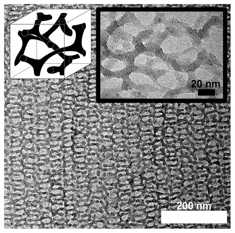
TEM image of free-standing mesoporous oxide double gyroid resulting from oxygen plasma removal of ISO structure directing agent from ISO4-S4. Schematic of the morphology (left inset) is next to the high magnification TEM image (right inset).
Niobia Nanocomposites
Seven additional samples were synthesized with a niobia sol in order to further explore the ISO-oxide phase diagram with the sol of a transition metal oxide. Samples spanned the ƒI=ƒS isopleth from 43.8 to 70.0 vol% O+oxide.
Five of these niobia nanocomposites had volume fractions within the 27 to 62 vol% O range of the three-domain lamellae phase of neat ISO polymers along the ƒI=ƒS isopleth.28 Only two of the five samples with the lowest O+oxide volume fraction, ISO4-N1 and ISO4-N2, with O+oxide fractions ranging from 43.8 to 48.2 vol%, were identified to have the Lam3 morphology by TEM and SAXS. The TEM images of these stained Lam3 nanocomposites had layers of O+oxide (dark), S (light), and I (gray) arranged in patterns of ISO-OSI- which is characteristic of this morphology (Figure 1C). The switching of O+oxide and stained I contrast in the niobia samples is due to the much higher atomic number of Nb (41) compared to Si (14) and Al (13). This results in the niobia providing more electron scattering contrast than the OsO4 stained I. The SAXS patterns of these two samples have peaks consistent with lamellar symmetry, with peaks at q/q*=1, √4, and √9 (Figure 2C). The d1 lattice spacing measured by SAXS varied from 24.0 to 26.3 nm and was consistent with both the observed c.a. 25 nm spacings observed in TEM and the molecular weight of the ISO polymer.
Niobia nanocomposites with O+oxide fractions beyond 50.0 vol% were found to form a different morphology. Neat ISO polymers are known to form core-shell double gyroid (Q230) and core-shell hexagonal phases in narrow composition windows on the O-rich side of the ISO phase diagram.28 Samples ISO4-N3 and ISO4-N4 had O+oxide fractions of 51.1 and 54.0 vol%, respectively, and both formed the same morphology. TEM images of these samples showed a hexagonal arrangement of continuous tubes of I (gray) covered with shells of S (white) within a matrix of O+oxide (dark) (Figure 1D). Although this image is similar to the aluminosilicate core-shell hexagonal image (compare Figure 1A and 1D), the I and O+oxide domains have switched places. Accordingly, this morphology is named core-shell inverse-hexagonal (CS-iH) since the O+oxide domain forms the matrix. The SAXS patterns of these two samples were also consistent with the observed hexagonal symmetry, showing scattering peaks at q/q*= 1, √3, and √4 (Figure 2D). The d10 spacing varied from 22.0 and 24.8 nm and was consistent with c.a. 23 nm spacings observed in TEM as well as the molecular weight of the ISO polymer used.
The niobia nanocomposites synthesized with 58 vol% O+oxide or more had macrophase separated regions of niobia. Samples ISO4-N5, ISO3-N1, and ISO3-N2 all had clear formation of precipitates throughout the films when viewed on the TEM (Figure 4). The precipitation of some of the niobia sol from solution leads to a lower effective volume fraction of niobia mixed with O block of the polymer. This is likely why ISO4-N5 with 58 vol% O+oxide exhibited a Lam3 morphology predominantly in TEM and SAXS (data not shown). Samples ISO3-N1 and ISO3-N2 also had clear macrophase separation, but still had the expected CS-iH morphology. The macrophase separation correlated to a decrease in d10 in the ordered regions relative to samples of similar composition (Table I).
Figure 4.
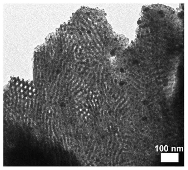
Representative TEM image of sample ISO3-N2 showing macrophase separation of niobia precipitates at high oxide loadings (>58 vol% O+oxide).
Discussion
The morphology results of 15 oxide nanocomposites structure-directed with 2 different ISO triblock terpolymers along the ƒI=ƒS isopleth are displayed in Figure 5. Due to the many parameters of this phase space, the two-dimensional ternary phase diagram represents a small slice of the complete phase space along this isopleth. In particular, the molecular weight (N), and volume fraction of O (ƒO) were only varied within a narrow range. Furthermore, this morphology map is a composite containing results from both aluminosilicate and niobia nanocomposites. Each morphology is discussed separately before the overall phase behavior of this isopleth is discussed.
Figure 5.

Morphology map for poly(isoprene-b-styrene-b-ethylene oxide) nanocomposites with axes indicating the volume fractions of I, S, and O+oxide. Symbols identify the polymer and oxide used. Four ordered morphologies were identified, including core-shell hexagonal, core-shell double gyroid, 3-domain lamellae, and core-shell inverse-hexagonal. The three samples with the highest O+oxide fractions had oxide precipitation from the polymer which lead to lower effective O+oxide volume fractions.
Core-shell Hexagonal Phase
The core-shell hexagonal phase was found to form in the composition window from 15.0 to 22.3 vol% O+oxide. This contrasts sharply from neat ISO which forms the O70 phase from 9.8 to 23.9 vol% O along the same isopleth. This CS-H phase was even observed when ISO4 (forms O70 when neat) was mixed with just 2.9 vol% aluminosilicate (ISO4-S1). Clearly, the system thermodynamics were strongly affected by the selective mixing of sol particles with the O domain. A similar suppression of the O70 phase was observed when relatively small amounts of lithium perchlorate were mixed with similar ISO polymers.4 The marked change in phase behavior was attributed to the 17-fold increase in segregation strength induced by the selective dissolution of lithium perchlorate into the O blocks. An analagous effect is likely at play in the ISO-oxide system. The effect of the addition of oxide nanoparticles on the segregation strength of ISO was crudely estimated41 by comparing the d* (=2π/q*) spacing of hexagonal ISO3 to that of ISO3-S2 using d* α χ 1/6. This approximation lead to an estimated increase in χ by a factor of 1.8 upon addition of oxide sol. While addition of oxide sol to ISO does not increase χ nearly as much as lithium perchlorate, it is still sufficient to explain the similar change in phase behavior. The CS-H phase was not only found at very low oxide loadings, but also into the dense nanoparticle regime.42 Sample ISO3-S3 formed the CS-H phase with an aluminosilicate volume fraction larger than the O vol fraction. The CS-H phase was stabilized by the increased segregation strength induced by very small amounts of oxide and was preserved into the dense nanoparticle regime.
Core-Shell Double Gyroid Phase
The core-shell double gyroid morphology was found with O+oxide volume fractions ranging from 23.0 to 32.3 vol%. This large 9.3 vol% O+oxide window is comparable to the 14.1 vol% O window for the O70 phase in neat ISO polymers along the same isopleth. From a synthetic standpoint, this wide phase window with ISO structure-directing agents makes the fabrication of materials with tri-functional network structures far easier than with diblock copolymers.31 The existence of this network structure in the ISO-oxide system was quite unexpected considering the suppression of all network phases when similar ISO polymers were selectively swelled with lithium salts.4 In this case, the less drastic increase in segregation strength for the ISO-oxide system likely leads to the replacement of O70 with CS-GD rather than the complete suppression of network phases.
Three-domain Lamellae Phase
The Lam3 phase was found with O+oxide fractions ranging from about 32.3 to 48.2 vol%. The Lam3 phase window for ISO-oxide is more narrow than that of neat ISO polymers (27 to 62 vol% O), but occurs over a similar region of the ƒI=ƒS isopleth. The considerable asymmetry of the phase boundaries about the ƒI=ƒS=ƒO=1/3 symmetric point is due to the asymmetry of the I, S, and O mer units as well as the asymmetry of the χ parameters19, 43 which was exaggerated by the addition of oxide sols.
Core-Shell Inverse-Hexagonal Phase
The core-shell inverse-hexagonal morphology was found when the O+oxide composition was between 51 and 54 vol%. Larger O+oxide fractions could be explored by starting with ISO polymers with larger O fractions or perhaps by modifying the niobia sol-gel process. However, such searches towards the O+oxide rich corner of the phase diagram are likely to result in isolated micellar phases or disordered mixing. The onset of the CS-iH at 51 vol% O+oxide is considerably lower than that predicted for neat ISO polymers (c.a. 70 to 80 vol% O)19 and is likely due to the increased segregation strength of the O+oxide domain. It is impressive to note how well the ISO-oxide system behaves deep into the dense nanoparticle regime. For example, ISO4-N4 with 54 vol% O+oxide contained 7.2 times more volume of oxide than O yet still formed a highly ordered morphology. All samples targeting O+oxide fractions higher than 54 vol% resulted in macrophase separation of niobia precipitates (ISO3-N1, ISO3-N2, and ISO4-N5). The isolated precipitates of niobia resulted in a lower effective O+oxide volume fraction. This lower effective O+oxide fraction led ISO4-N5 to form a Lam3 phase even though the recipe targeted an O+oxide region of phase space near CSiH. This lower effective O+oxide fraction was further evidenced in SAXS by a shift to smaller d* spacings (compare ISO4-N4 to ISO4-N5 and ISO3-N1 to ISO3-N2).
Phases Encountered
The phase behavior observed in the ISO-oxide system was characteristic of the non-frustrated ISO polymers used. All of the observed phases – CS-H, CS-GD, Lam3, and CS-iH – exhibited only A-B and B-C type interfaces without any A-C type contacts. The four observed phases were all core-shell analogs of the lamellar, double gyroid, and hexagonal phases common to diblock copolymers and appeared in same sequence. The very different phase space of the ISO-oxide system relative to neat ISO is attributed to the change in system thermodynamics which was evidenced even at very low oxide loadings.
The network morphology observed in the ISO-oxide system differed substantially from neat ISO. Along the ƒI=ƒS isopleth neat ISO polymers form the orthorhombic O70 phase on the O minority side of the isopleth from 9.8 to 23.9 vol% O and the cubic core-shell double gyroid on the O majority side of the isopleth from 61 to 67 vol% O.28 In contrast, the ISO-oxide system differed in two regards: 1) the cubic core-shell double gyroid structure formed on the O+oxide minority side of the isopleth and 2) no network phases were found on the O+oxide majority side of the isopleth. The appearance of the CS-GD phase on the O+oxide minority side of the isopleth, 1), can be rationalized by a slight distortion of neat ISO phase boundries19 by extending the CS-GD phase space slightly towards the I corner of the ternary phase diagram. The change in ISO thermodynamics with the addition of oxide sol could be attributed to such a shift. As predicted for neat ISO, the symmetric-asymmetric ISO structure-directing agents lead to an ISO-oxide network structure with saddle surfaces.26 In contrast the lack of any observed network structures on the O+oxide majority side of the isopleth, 2), requires further discussion. Although the existence of an ISO-oxide network phase on the O+oxide majority side of the isopleth cannot be disproved, it is not expected for the polymers used in this study since no such phases were observed as minority phases in samples ISO4-N2 or ISO4-N3 near the transition from Lam3 to CS-iH. We suspect that O+oxide majority network phases are suppressed by the entropic penalty associated with the O chain stretching necessary to reach the center of each node. This effect was likely exacerbated by the relatively small O fraction of the ISO polymers used in this study as well as the increased unit cell size at high oxide loadings. For comparison, such O+oxide majority network phases for IO diblock copolymers are know to form under a narrow set of conditions including a larger 32 vol% O.31, 39 Furthermore, the stability of ISO-oxide network phases may be rationalized in terms of the increased polydispersity of the combined O+oxide domain. Copolymers with blocks of different polydispersity are known to favor structures with surfaces curving towards the block of higher dispersity.44–47 Thus the stability of O+oxide minority network phases is expected to be higher than that of O+oxide majority network phases. There is likely a narrow set of conditions under which the ISO-oxide system forms network phases on the O+oxide majority side of the ƒI=ƒS isopleth, however, we don’t expect these conditions to be as experimentally tractable as when O+oxide is a minority.
Outlook for Applications
The reported CS-H, CS-GD, Lam3, and CS-iH morphologies could be useful for applications requiring continuous paths of multiple functional materials. The core-shell hexagonal morphologies contain a continuous matrix with two minority components that are continuous in one dimension whereas the Lam3 phase has all three components continuous in two dimensions. In contrast, the CS-GD morphology has a pentacontinuous structure with all five-plies continuous in all directions. A series of selective domain transformations48–50 could be used to convert the materials reported here into nanocomposites containing multiple function materials with either anisotropic or isotropic continuity. Such materials could be useful for advanced applications including photonic materials as well as energy generation, conversion, and storage devices.
Furthermore, ordered materials with continuous porosity are of interest for filtration, electronic, and optical applications. Towards this end we demonstrated a free-standing mesoporous aluminosilicate double gyroid (Figure 3). Such materials could be directly used as orientation independent filters. Alternatively, these free-standing oxide networks could be used as sacrificial hard templates for the synthesis of mesoporous, crystalline transition metal oxides51. Similarly, these oxide networks could also be used as substrates for the deposition of layers of functional materials for 3-dimensionally continuous electronic and optical devices.
Conclusion
The results of 15 ISO-oxide nanocomposites were detailed along the ƒI=ƒS isopleth using aluminosilicate and niobia sols. Four morphologies were identified, including core-shell hexagonal, core-shell double gyroid, three-domain lamellae, and core-shell inverse-hexagonal. These three- and five-ply nanocomposites contained continuous domains spanning in either one, two, or three dimensions. We believe that this approach will lead to advanced materials and devices containing several plies of functional materials.
Acknowledgments
This work was supported by the Cornell Fuel Cell Institute via the Cornell Center for Materials Research, a Materials Research Science and Engineering Center of the National Science Foundation (NSF DMR-0520404). This publication was further supported by a Grant Number R21DE018335 from the National Institute of Dental and Craniofacial Research. This work was supported at the University of Minnesota by the NSF (DMR 0220460 and by the MRSEC Program of the National Science Foundation under Award Number DMR-0212302 and DMR-0819885). This work made use of the Cornell Center for Materials Research Shared Facilities, supported through the NSF Materials Research Science and Engineering Centers program. The X-ray equipment was supported by Department of Energy grant DEFG-02-97ER62443. CHESS was supported by the NSF and NIH-NIGMS via DMR-0225180.
References
- 1.Templin M, Franck A, DuChesne A, Leist H, Zhang YM, Ulrich R, Schadler V, Wiesner U. Organically modified aluminosilicate mesostructures from block copolymer phases. Science. 1997;278(5344):1795–1798. doi: 10.1126/science.278.5344.1795. [DOI] [PubMed] [Google Scholar]
- 2.Yang PD, Zhao DY, Margolese DI, Chmelka BF, Stucky GD. Generalized syntheses of large-pore mesoporous metal oxides with semicrystalline frameworks. Nature. 1998;396(6707):152–155. [Google Scholar]
- 3.Zhao DY, Feng JL, Huo QS, Melosh N, Fredrickson GH, Chmelka BF, Stucky GD. Triblock copolymer syntheses of mesoporous silica with periodic 50 to 300 angstrom pores. Science. 1998;279(5350):548–552. doi: 10.1126/science.279.5350.548. [DOI] [PubMed] [Google Scholar]
- 4.Epps TH, Bailey TS, Waletzko R, Bates FS. Phase behavior and block sequence effects in lithium perchlorate-doped poly(isoprene-b-styrene-b-ethylene oxide) and poly(styrene-b-isoprene-b-ethylene oxide) triblock copolymers. Macromolecules. 2003;36(8):2873–2881. [Google Scholar]
- 5.Toombes GES, Mahajan S, Thomas M, Du P, Tate MW, Gruner SM, Wiesner U. Hexagonally patterned lamellar morphology in ABC triblock copolymer/aluminosilicate nanocomposites. Chemistry of Materials. 2008;20(10):3278–3287. [Google Scholar]
- 6.Toombes GES, Mahajan S, Weyland M, Jain A, Du P, Kamperman M, Gruner SM, Muller DA, Wiesner U. Self-assembly of four-layer woodpile structure from zigzag ABC copolymer/aluminosilicate concertinas. Macromolecules. 2008;41(3):852–859. [Google Scholar]
- 7.Mogi Y, Kotsuji H, Kaneko Y, Mori K, Matsushita Y, Noda I. Preparation and Morphology of Triblock Copolymers of the ABC Type. Macromolecules. 1992;25(20):5408–5411. [Google Scholar]
- 8.Auschra C, Stadler R. New Ordered Morphologies in ABC Triblock Copolymers. Macromolecules. 1993;26(9):2171–2174. [Google Scholar]
- 9.Krappe U, Stadler R, Voigtmartin I. Chiral Assembly in Amorphous ABC Triblock Copolymers - Formation of a Helical Morphology in Polystyrene-block-polybutadiene-block-poly(methyl methacrylate) Block-Copolymers. Macromolecules. 1995;28(13):4558–4561. [Google Scholar]
- 10.Zheng W, Wang Z-G. Morphology of ABC Triblock Copolymers. Macromolecules. 1995;28(21):7215–7223. [Google Scholar]
- 11.Matsushita Y, Suzuki J, Seki M. Surfaces of tricontinuous structure formed by an ABC triblock copolymer in bulk 1998. Elsevier Science Bv; 1998. pp. 238–242. [Google Scholar]
- 12.Shefelbine TA, Vigild ME, Matsen MW, Hajduk DA, Hillmyer MA, Cussler EL, Bates FS. Core-shell gyroid morphology in a poly(isoprene-block-styrene-block-dimethylsiloxane) triblock copolymer. J Am Chem Soc. 1999;121(37):8457–8465. [Google Scholar]
- 13.Bates FS, Fredrickson GH. Block copolymers - Designer soft materials. Phys Today. 1999;52(2):32–38. [Google Scholar]
- 14.Bailey TS, Hardy CM, Epps TH, Bates FS. A noncubic triply periodic network morphology in poly(isoprene-b-styrene-b-ethylene oxide) triblock copolymers. Macromolecules. 2002;35(18):7007–7017. [Google Scholar]
- 15.Ludwigs S, Boker A, Abetz V, Muller AHE, Krausch G. Phase behavior of linear poly styrene-block-poly (2-vinylpyridine)-block-poly(tert-butyl methacrylate) triblock terpolymers. Polymer. 2003;44(22):6815–6823. [Google Scholar]
- 16.Walther A, Goldel A, Muller AHE. Controlled crosslinking of polybutadiene containing block terpolymer bulk structures: A facile way towards complex and functional nanostructures. Polymer. 2008;49(15):3217–3227. [Google Scholar]
- 17.Jinnai H, Kaneko T, Matsunaga K, Abetz C, Abetz V. A double helical structure formed from an amorphous, achiral ABC triblock terpolymer. Soft Matter. 2009;5(10):2042–2046. [Google Scholar]
- 18.Bates FS. Network phases in block copolymer melts. Mrs Bulletin. 2005;30(7):525–532. [Google Scholar]
- 19.Tyler CA, Qin J, Bates FS, Morse DC. SCFT study of nonfrustrated ABC triblock copolymer melts. Macromolecules. 2007;40(13):4654–4668. [Google Scholar]
- 20.Floudas G, Ulrich R, Wiesner U. Microphase separation in poly(isoprene-b-ethylene oxide) diblock copolymer melts. I. Phase state and kinetics of the order-to-order transitions. J Chem Phys. 1999;110(1):652–663. [Google Scholar]
- 21.Stefik M, Sai H, Sauer K, Gruner SM, DiSalvo FJ, Wiesner U. Three-Component Porous-Carbon-Titania Nanocomposites through Self-Assembly of ABCBA Block Terpolymers with Titania Sols. Macromolecules. 2009;42(17):6682–6687. [Google Scholar]
- 22.Crossland EJW, Kamperman M, Nedelcu M, Ducati C, Wiesner U, Smilgies DM, Toombes GES, Hillmyer MA, Ludwigs S, Steiner U, Snaith HJ. A Bicontinuous Double Gyroid Hybrid Solar Cell. Nano Letters. 2008 doi: 10.1021/nl803174p. [DOI] [PubMed] [Google Scholar]
- 23.Stefik M, Lee J, Wiesner U. Nanostructured carbon-crystalline titania composites from microphase separation of poly(ethylene oxide-b-acrylonitrile) and titania sols. Chem Commun. 2009;18:2532–2534. doi: 10.1039/b818972b. [DOI] [PubMed] [Google Scholar]
- 24.Bailey TS. Thesis. University of Minnesota; 2001. Morphological behavior spanning the symmetric AB and ABC block copolymer states. [Google Scholar]
- 25.Bailey TS, Pham HD, Bates FS. Morphological Behavior Bridging the Symmetric AB and ABC States in the Poly(styrene-b-isoprene-b-ethylene oxide) Triblock Copolymer System. Macromolecules. 2001;34(20):6994–7008. [Google Scholar]
- 26.Epps TH, Cochran EW, Bailey TS, Waletzko RS, Hardy CM, Bates FS. Ordered network phases in linear poly(isoprene-b-styrene-b-ethylene oxide) triblock copolymers. Macromolecules. 2004;37(22):8325–8341. [Google Scholar]
- 27.Fetters LJ, Lohse DJ, Richter D, Witten TA, Zirkel A. Connection Between Polymer Molecular-Weight, Density, Chain Dimensions, and Melt Viscoelastoc Properties. Macromolecules. 1994;27(17):4639–4647. [Google Scholar]
- 28.Chatterjee J, Jain S, Bates FS. Comprehensive phase behavior of poly(isoprene-b-styrene-b-ethylene oxide) triblock copolymers. Macromolecules. 2007;40(8):2882–2896. [Google Scholar]
- 29.Warren SC, Disalvo FJ, Wiesner U. Nanoparticle-tuned assembly and disassembly of mesostructured silica hybrids (vol 6, pg 156, 2007) Nature Materials. 2007;6(3):248–248. doi: 10.1038/nmat1819. [DOI] [PubMed] [Google Scholar]
- 30.Simon PFW, Ulrich R, Spiess HW, Wiesner U. Block copolymer-ceramic hybrid materials from organically modified ceramic precursors. Chemistry of Materials. 2001;13(10):3464–3486. [Google Scholar]
- 31.Finnefrock AC, Ulrich R, Toombes GES, Gruner SM, Wiesner U. The plumber’s nightmare: A new morphology in block copolymer-ceramic nanocomposites and mesoporous aluminosilicates. J Am Chem Soc. 2003;125(43):13084–13093. doi: 10.1021/ja0355170. [DOI] [PubMed] [Google Scholar]
- 32.Jain A, Toombes GES, Hall LM, Mahajan S, Garcia CBW, Probst W, Gruner SM, Wiesner U. Direct access to bicontinuous skeletal inorganic plumber’s nightmare networks from block copolymers. Angewandte Chemie-International Edition. 2005;44(8):1226–1229. doi: 10.1002/anie.200461156. [DOI] [PubMed] [Google Scholar]
- 33.Jain A, Hall LM, Garcia CBW, Gruner SM, Wiesner U. Flow-induced alignment of block copolymer-sol nanoparticle coassemblies toward oriented bulk polymer-silica hybrids. Macromolecules. 2005;38(24):10095–10100. [Google Scholar]
- 34.Cho BK, Jain A, Gruner SM, Wiesner U. Nanoparticle-induced packing transition in mesostructured block dendron-silica hybrids. Chemistry of Materials. 2007;19(15):3611–3614. [Google Scholar]
- 35.Lee J, Orilall MC, Warren SC, Kamperman M, Disalvo FJ, Wiesner U. Direct access to thermally stable and highly crystalline mesoporous transition-metal oxides with uniform pores. Nature Materials. 2008;7(3):222–228. doi: 10.1038/nmat2111. [DOI] [PubMed] [Google Scholar]
- 36.Alberius PCA, Frindell KL, Hayward RC, Kramer EJ, Stucky GD, Chmelka BF. General predictive syntheses of cubic, hexagonal, and lamellar silica and titania mesostructured thin films. Chemistry of Materials. 2002;14(8):3284–3294. [Google Scholar]
- 37.Tate MW, Eikenberry EF, Barna SL, Wall ME, Lowrance JL, Gruner SM. A Large-Format High-Resolution Area X-Ray-Detector based on a Fiberoptically Bonded Charge-Coupled-Device (CCD) Journal of Applied Crystallography. 1995;28:196–205. [Google Scholar]
- 38.Klotz M, Albouy PA, Ayral A, Menager C, Grosso D, Van der Lee A, Cabuil V, Babonneau F, Guizard C. The true structure of hexagonal mesophase-templated silica films as revealed by X-ray scattering: Effects of thermal treatments and of nanoparticle seeding. Chemistry of Materials. 2000;12(6):1721–1728. [Google Scholar]
- 39.Toombes GES, Finnefrock AC, Tate MW, Ulrich R, Wiesner U, Gruner SM. A re-evaluation of the morphology of a bicontinuous block copolymer-ceramic material. Macromolecules. 2007;40(25):8974–8982. [Google Scholar]
- 40.Urade VN, Wei T-C, Tate MP, Kowalski JD, Hillhouse HW. Nanofabrication of Double-Gyroid Thin Films. Chemistry of Materials. 2007;19(4):768–777. [Google Scholar]
- 41.Semenov AN. Microphase separation in diblock-copolymer melts: ordering of micelles. Macromolecules. 2002;22(6):2849–2851. [Google Scholar]
- 42.Jain A, Wiesner U. Silica-type mesostructures from block copolymer phases: Formation mechanism and generalization to the dense nanoparticle regime. Macromolecules. 2004;37(15):5665–5670. [Google Scholar]
- 43.Floudas G, Vazaiou B, Schipper F, Ulrich R, Wiesner U, Iatrou H, Hadjichristidis N. Poly(ethylene oxide-b-isoprene) diblock copolymer phase diagram. Macromolecules. 2001;34(9):2947–2957. [Google Scholar]
- 44.Lynd NA, Hillmyer MA. Influence of polydispersity on the self-assembly of diblock copolymers. Macromolecules. 2005;38(21):8803–8810. [Google Scholar]
- 45.Cooke DM, Shi AC. Effects of polydispersity on phase behavior of diblock copolymers. Macromolecules. 2006;39(19):6661–6671. [Google Scholar]
- 46.Ruzette AV, Tence-Girault S, Leibler L, Chauvin F, Bertin D, Guerret O, Gerard P. Molecular disorder and mesoscopic order in polydisperse acrylic block copolymers prepared by controlled radical polymerization. Macromolecules. 2006;39(17):5804–5814. [Google Scholar]
- 47.Meuler AJ, Ellison CJ, Qin J, Evans CM, Hillmyer MA, Bates FS. Polydispersity effects in poly(isoprene-b-styrene-b-ethylene oxide) triblock terpolymers. J Chem Phys. 2009;130(23) doi: 10.1063/1.3140205. [DOI] [PubMed] [Google Scholar]
- 48.Hillmyer MA. Nanoporous materials from block copolymer precursors. Block Copolymers II. 2005;190:137–181. [Google Scholar]
- 49.Ryoo R, Joo SH, Jun S. Synthesis of highly ordered carbon molecular sieves via template-mediated structural transformation. J Phys Chem B. 1999;103(37):7743–7746. [Google Scholar]
- 50.Lee J, Yoon S, Hyeon T, Oh SM, Kim KB. Synthesis of a new mesoporous carbon and its application to electrochemical double-layer capacitors. Chem Commun. 1999;21:2177–2178. [Google Scholar]
- 51.Tian B, Liu X, Solovyov LA, Liu Z, Yang H, Zhang Z, Xie S, Zhang F, Tu B, Yu C, Terasaki O, Zhao D. Facile Synthesis and Characterization of Novel Mesoporous and Mesorelief Oxides with Gyroidal Structures. J Am Chem Soc. 2003;126(3):865–875. doi: 10.1021/ja037877t. [DOI] [PubMed] [Google Scholar]