Abstract
Active physiological tremor compensation instruments have been under research and development recently. The sensing unit of the instruments provides information on three degrees-of-freedom (DOF) motion of the instrument tip using accelerations provided by accelerometers placed inside the instruments. A complete vector of angular acceleration of the instrument needs to be known to obtain information on three DOF motions of the tip. Sensing resolution of angular acceleration about the instrument axis is directly proportional to the width of the proximal-end sensing unit. To keep the sensing resolution high enough, the width of the unit has to be made large. As a result, the proximal-end sensing unit of the instruments is bulky. In this paper, placement of accelerometers is proposed such that the angular acceleration about the instrument axis need not be known to obtain information on the three DOF motions of the tip. With the proposed placement, the instrument is no longer bulky and fewer number of accelerometers is required, thereby making the instrument compact and better in terms of ergonomics and reliability. Experiments were conducted to show that the proposed design of placement works properly.
Index Terms: Accelerometer placement, compact sensing design, handheld instruments, physiological tremor compensation
I. Introduction
To Improve micromanipulation accuracy of surgeons, a number of engineered devices or systems have been or are being developed. These include telerobotics systems [1], steady-hand robotics systems [2], and “Micron” instruments [3] which are handheld active tremor compensation instruments which have been under research and development for a few years. Micron instruments can be divided into three main parts; sensing, filtering or processing of sensed data, and manipulation. In the sensing part, micromachined accelerometers are employed to sense six degree-of-freedom (DOF) motion of the instrument due to their compactness, cheapness and the fact, which is shown in [4] and [5], that angular motion derived from micromachined accelerometers has better sensing resolution than that obtained from micromachined gyros for a given space inside the instrument. A photo and a schematic diagram of the placement of accelerometers in the Micron instrument are shown in Fig. 1.
Fig. 1.
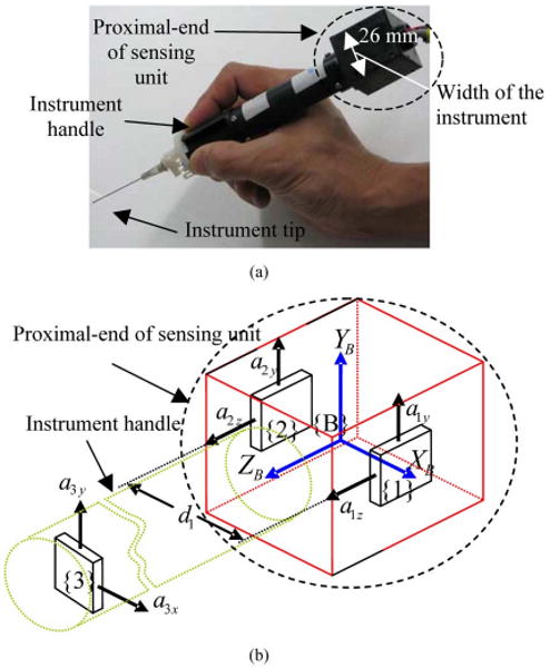
Micron instrument sensing unit: (a) a photo and (b) a schematic diagram of placement of accelerometers and a frame {B} attached to the instrument.
Chen et al. [6] proposed an original cube configuration design with six accelerometers, the minimum number of sensors to recover all the six kinematic parameters. Zappa et al. [7] proposed 12 accelerometers to measure rigid body motion. Wang et al. [8] proposed nine-accelerometers scheme to get angular velocity directly without integration from angular acceleration. Tan and Park [9] analyzed the effects of accelerometer location and orientation errors on the calculation results of angular and linear motions. Latt et al. [10] proposed placement of accelerometers in a handheld instrument to obtain high resolution in sensing of three DOF angular motions.
As described in [10], sensing resolution of angular acceleration is directly proportional to the separation distance between corresponding two accelerometers. A complete angular acceleration vector (i.e., angular accelerations about three orthogonal principal axes) is required to calculate the instrument tip motion. Calculation of the angular acceleration about the instrument axis (or ZB axis), αz is shown in (1) and its resolution is directly proportional to the separation distance, d1 (see Fig. 1), between the two accelerometers at locations {1} and {2} across the instrument. If the width of the instrument is small, d1 is small and the sensing resolution is low. Therefore, the width of the sensing unit at the proximal-end of the instrument could not be made too slim for the sake of sensing resolution of angular motion
| (1) |
Patkin [11] discussed that instruments that are heavy or stiff, and thick-handled would be clumsier and increase tremor. Although no discussion was made on the bulkiness of the instrument, it is apparent that bulky instruments will be more disruptive to surgeons/users than compact instruments due to the lack of mobility and potential blockage of user's view to the target by the instrument itself.
The greater the loading on the fingertip by weights, the more physiological tremor is increased [11]. More weight at the end of the instrument will result in more loading on the fingertip because thumb cleft serves as a fulcrum point of the instrument. For that reason, possible adding of weight at the proximal end of the instrument should be avoided in designing instruments. On the other hand, as described previously, the width of the proximal-end sensing unit cannot be made too small and hence there is a compromise between the resolution and the ergonomics. If angular acceleration about instrument axis αz is not required in the calculation of tip acceleration vector, the proximal-end sensing unit can be made smaller and hence the problems associated with the bulkiness and heaviness of the instrument can be eliminated.
It has been recently shown that physiological tremor motion information can be obtained without having to know absolute orientation of the instrument with respect to the world frame [12]. That means angular acceleration information is not required for a complete orientation of the instrument with respect to the world frame. The only requirement of information on angular acceleration is in kinematic calculation to obtain complete vector information on acceleration of the tip. In previous sensing designs of tremor compensation instruments [4], [10], complete vector information on angular acceleration of the instrument is required to obtain complete vector information on the acceleration of the tip. However, if the placement of accelerometers is carefully considered, the information on angular acceleration about ZB axis, αz, may not be required or no angular acceleration component may be required at all. For the reasons stated above, we analyze the accelerometer placements and propose a placement design which does not require information on angular acceleration about ZB axis.
II. Methodology
A. Basic Kinematics
In this section, we describe how acceleration at a particular location on a rigid body can be calculated using acceleration information at another location on the body which is some known distance away from the former.
If accelerometers are fixed on a rigid body, the total accelerations, Ai = [aix aiy aiz]T, each accelerometer at {i} in rigid body frame {B} senses include the inertial acceleration of the body, AIN, the gravity, G, and the rotation-induced accelerations: the centripetal acceleration, Ai/C, and the tangential acceleration, Ai/T
| (2.a) |
| (2.b) |
where all the variables are relative to the body frame {B}, Ω = [ωx ωy ωz]T is the angular velocity vector with respect to body frame, {B}, R is the vector from the unknown instantaneous center of rotation to the accelerometer location {i}, n is the number of accelerometers.
Taking the difference between the acceleration readings at two different locations, for simplicity and without losing generality, let us say, at {1} and {2}, the nonrotation induced acceleration components AIN and G are eliminated since the linear inertial acceleration of the body and the gravity should be identical at different locations, and rotation-induced accelerations are obtained
| (3) |
where P12 = [p12x p12y p12z]T is position vector from {1} to {2}. α = [αx αy αz]T is angular acceleration vector. Rearranging (3)
| (4) |
According to (4), acceleration at location {2} can be known if acceleration reading at {1}, angular velocity, and angular acceleration are known. Therefore, in general, calculation of motion-induced acceleration at a point {p}, Ap = [aPx apy apz]T, which is some known distance away from an accelerometer at location {i} is as follows:
| (5) |
where Pip = [pipx pipy pipz]T is the displacement vector from locations {i} and {p}, Aip = Ap − Ai.
In micromanipulation tasks, the angular velocity of the instrument has been found to be almost always very small and the centripetal acceleration terms Ω × (Ω × Pip) in (5) can be ignored [13] and (5) becomes
| (6) |
Expanding (6) into components form
| (7) |
B. Obtaining Complete Vector Information on Acceleration of the Tip
In this section, we describe how the complete vector information on acceleration of the instrument tip can be obtained using acceleration readings from accelerometers fixed in the instrument. Since there are three components in the acceleration vector, at least three accelerometers each sensing in different principal axis direction is required. Assuming accelerometers at location {1}, {2}, and {3} sense accelerations in X, Y, and Z principal axis direction respectively, and using (7), acceleration at the instrument tip Ae = [aex aey aez]T is found to be as follows:
| (8.a) |
| (8.b) |
| (8.c) |
where pied, i = 1, 2, 3; d = x, y, z, is the displacement between location {i} and the instrument tip along d principal axis. According to (8.a)–(8.c), apart from the three orthogonal acceleration readings from three accelerometers, three angular accelerations about three axes are required to get all the three acceleration components at the tip.
1) Placement of an Accelerometer to Sense Acceleration Component in the Instrument Axis Direction, aez
In this section, we describe how the acceleration component in instrument axis direction, aez, is obtained without requiring any angular acceleration. In (7)
| (9.a) |
| (9.b) |
| (9.c) |
The conditions for (9.a) and (9.c) are illustrated in Fig. 2. In the figure, acceleration component in ZB axis direction at point A and that at point B are the same since pABx = pABy = 0. Similarly, acceleration component in XB axis direction at point D is the same as that at point C since pCDz = pCDy = 0.
Fig. 2.
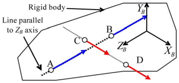
Illustration of the locations which have the same acceleration component in a particular axis direction (assuming angular velocity is small enough to be neglected).
The above concept helps us to design a sensing system with fewer accelerometers. In general, if we could place accelerometers, as shown in Fig. 3, only three accelerometers are all that is needed to obtain the complete vector information on acceleration of the tip. In Fig. 3, accelerometers are placed on loci of lines I, II, and III for sensing acceleration along XB, YB, and ZB axes, respectively. For this configuration of accelerometer placement, no angular acceleration is required because p1ez = p1ey = 0 in (8.a) to calculate aex, p2ex = P2ez = 0 in (8.b) to get aey and p3ey = p3ex = 0 in (8.c) to get aez.
Fig. 3.
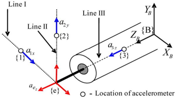
Theoretical placement of accelerometers to get a complete acceleration vector at the top without requiring angular motion information.
Although there is no problem in placing an accelerometer on the line III, the instrument axis, to sense aez, there are some implementation and ergonomic issues with placement of the other two accelerometers on lines I and II, and hence the two accelerometers are not placed on the lines I and II, while an accelerometer is placed on the instrument axis to sense aez, as shown in Fig. 4. From (8.c), since p3ey = p3ex = 0, aez = a3z meaning that the acceleration component at the tip in Z axis direction is just simply the accelerometer output.
Fig. 4.
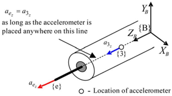
Placement of an accelerometer to sense acceleration component at the tip along ZB axis direction.
2) Placement of Accelerometers To Sense Acceleration Components in the Other Two Axes, aex and aey
Placing the other two accelerometers on the instrument axis for sensing acceleration in XB axis, and YB axis directions, as shown in Fig. 5, will eliminate the requirement of information on angular acceleration about ZB axis since p1ey = 0 for the calculation of aex in (8.a) and p2ex= 0 for aey in (8.b). With the placement shown in Fig. 5, acceleration at the tip in YB axis, aey can be calculated as
Fig. 5.
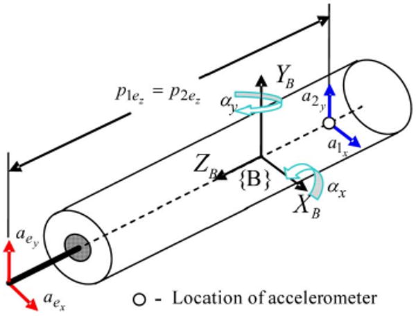
Placement of two accelerometers which require only two angular motion information to (αy and αy) obtain acceleration components in XB axis and YB axis directions.
| (10) |
Acceleration at the tip in XB axis direction can be calculated as
| (11) |
3) Requirement to Obtain Complete Vector Information on Acceleration of the Tip
Combining the placement of accelerometers in Figs. 4 and 5, complete vector information on acceleration of the tip is obtained. As can be seen from Figs. 4 and 5, obtaining complete vector information on the acceleration of the tip requires at least three accelerometers sensing along three principal axes, and angular accelerations about XB and YB axes (αx and αy).
To get required angular accelerations, micromachined gyroscopes can be employed. However, angular sensing information obtained from micromachined gyroscopes have poorer sensing resolution comparing to that obtained from micromachined accelerometers for the space available inside the instrument [4], [5], and hence accelerometers are employed in the instrument to get required angular acceleration vector. To get required angular accelerations, accelerometers are placed, as shown in Fig. 6.
Fig. 6.
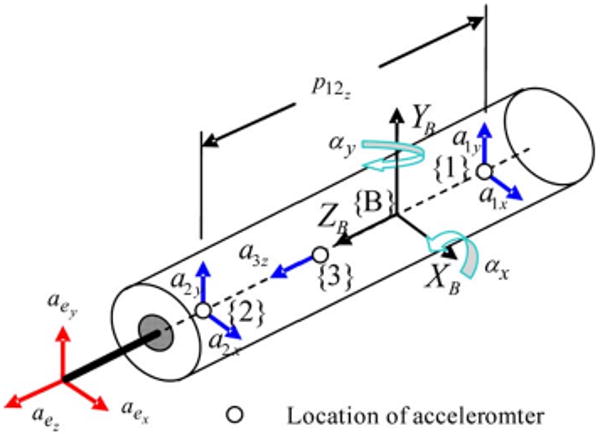
Placement of accelerometers to get a complete acceleration vector at the tip.
The calculations of αx and αy are simply as follows. Equation (3) is rewritten here
Again, in micromanipulation tasks, angular velocity is almost always very small. Hence, (3) becomes
| (12) |
In components form, (12) becomes
Since p12x = p12y = 0
| (13) |
| (14) |
| (15) |
III. Analysis on the Effect of Inaccurate Positioning of Accelerometers
In practice, accelerometers cannot be positioned exactly on the instrument axis due to imperfection in machining of the parts. However, machining accuracy of about 0.1 mm is easily achievable. The positioning error can also come from inaccurate placement of accelerometer integrated circuit (IC) onto a printed circuit board (PCB). This cannot be higher than 0.1 mm if soldering of accelerometers is done with automatic soldering machines. The assembly of the parts will introduce the biggest error which can be up to about 0.3 mm. The overall worst case positioning error is therefore assumed to be 0.5 mm.
A. Effect of Accelerometers Positioning Error on Angular Acceleration
Equations (14) and (15) are true only if accelerometers are placed perfectly, as shown in Fig. 6. In the case of errors in positioning of accelerometers on the ideal positions, as shown in Fig. 7, αy and αx become as follows:
Fig. 7.
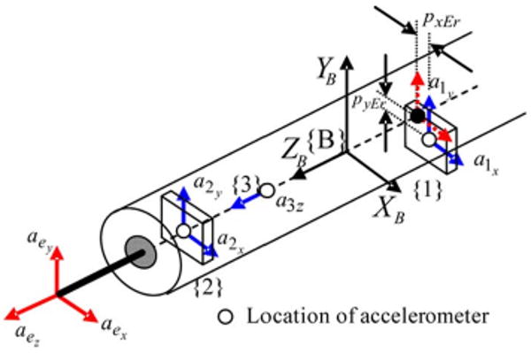
Illustration of error in positioning of accelerometers.
| (16) |
| (17) |
Separating the error term, (16) and (17) become
| (18) |
| (19) |
where pdEr, d = x, y, is offset distance from ideal positions in d axis. According to experimental results obtained from ten normal subjects who performed micromanipulation tasks using a handheld instrument, the mean of maximum amplitudes of tremor angular acceleration about the instrument's axis, αz is about 4 rad/s2 [9].
Using the positioning error of 0.5 mm and the angular acceleration of about 4 rad/s2, the error, the contribution of αzpdEr, is found to be about 2 mm/s2. Dividing the error due to αzpdEr by p12z which is about 100 mm, the angular acceleration error is known [see (18) and (19)] and it becomes 0.02 rad/s2. This is the maximum possible angular acceleration error and is about five times lesser than the noise floor value of an angular acceleration component which is 0.1 rad/s2. Therefore, it can safely be assumed to be negligible.
B. Effect of Accelerometers Positioning Error on the Tip Acceleration
Although the positioning error has negligible effect on angular acceleration, it might have some effect on the tip acceleration calculation. With the proposed placement of accelerometers, as shown in Fig. 7, and using (7), tip acceleration is calculated, in general, as follows:
| (20) |
| (21) |
| (22) |
If there is no error in measurement and positioning of accelerometers, (20)–(22) become
| (23) |
| (24) |
| (25) |
In practice, measurement errors and positioning errors exist and (23–25) become
| (26) |
| (27) |
| (28) |
where piezEr is measurement error of displacement from accelerometer {i} to the tip in ZB axis direction. piedEr, d = x, y, is positioning error in d axis of accelerometer {i} on the instrument axis that passes through the tip. Rewriting (26–28) to separate error terms
| (29) |
| (30) |
| (31) |
From (29), error in acceleration component in XB axis, aexEr is
| (32) |
Assuming the maximum measurement error is also about 1 mm, and putting in the maximum errors and maximum angular acceleration in (32), maximum error in the calculation of the acceleration component at the tip in XB axis aexEr is obtained as follows:
Similarly, maximum error in acceleration component in YB axis, aeyEr, and that in ZB axis, are found to be 8 mm/s2 by substituting the maximum errors in (33) and (34)
| (33) |
| (34) |
IV. Experiments and Results
A compact version of Micron instrument called “ITrem” was developed with the sensing part as shown in Fig. 8. The placement of accelerometers in the sensing part is according to the proposed design shown in Fig. 6. Accelerometers employed are dual-axis miniature MEMS accelerometers (ADXL203, Analog Devices, USA). The comparison of the size of ITrem and that of Micron is shown in Fig. 9.
Fig. 8.
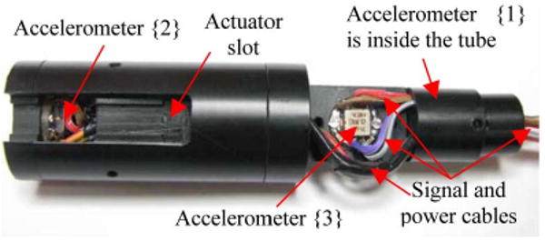
Photo of the accelerometers inside the ITrem instrument without the actuators and mechanism at the distal end.
Fig. 9.
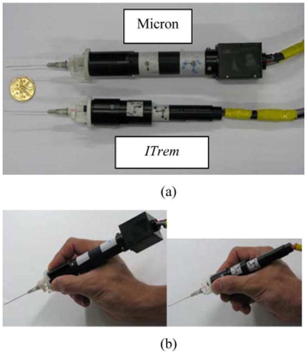
Comparison of the sizes of the instruments.
To confirm that the angular acceleration formulae described in (14) and (15) are valid, an experiment was conducted. The ITrem was placed on a one degree-of-freedom rotating arm, as shown in Fig. 10. The distal end of the sensing part was attached with a nonreflective black color rod. The tip of the rod was attached with a reflective ball whose location was sensed using an optical-based micro motion sensing system, M2S2 [14], [15]. The location of the ball with respect to the center of rotation of the rotating arm is known.
Fig. 10.
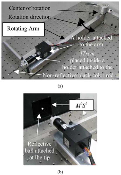
A photo of (a) the ITrem instrument attached to the rotating arm and (b) close-up view of the instrument tip placed near to the workspace of M2S2.
Rotational motion of the instrument was produced by shaking the rotating arm horizontally back-and-forth. The rotational acceleration of the instrument was calculated from the M2S2 measured positions of the ball which is attached to the instrument. The measured position of the ball was then double-differentiated to obtain the ball acceleration which was further divided by the distance from the location of the ball to the center of rotation to obtain angular acceleration. Since the angular acceleration obtained contains noise due to the differentiation, offline zero-phase bandpass filtering was performed using a fourth-order bandpass filter having a passband of 7–13 Hz. The filtered angular acceleration was used as a ground truth angular acceleration.
The comparison of ground truth angular acceleration about YB axis and the calculated angular acceleration about YB axis obtained using the formula (15) and the acceleration readings from the accelerometers in ITrem was shown in Fig. 11. The calculated angular acceleration from ITrem was also filtered using the same bandbass filter used in obtaining the ground-truth angular acceleration.
Fig. 11.
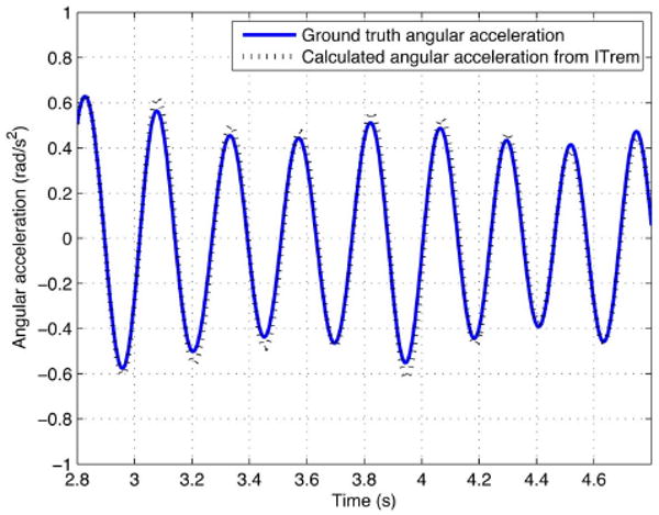
Comparison of ground truth angular acceleration about YB axis and calculated angular acceleration about YB axis using acceleration outputs from accelerometers inside the instrument.
To prove the kinematic equations described in (23–25) are correct, an experiment was conducted. The positions of the ball attached to the tip of the instrument were measured while the instrument was being held, as shown in Fig. 12. The instrument was held in a manner that orientation of the instrument with respect to the M2S2 is known. Four trials were conducted with each trial lasting for 16 s. Tip positions and accelerations due to tremor obtained from ITrem and M2S2 were used for evaluation of ITrem sensing.
Fig. 12.
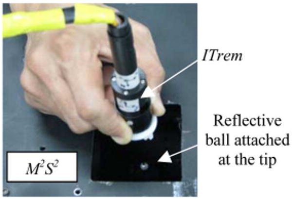
A photo taken while tremor motion of the ball was being measured using M2S2, as well as accelerometers inside the ITrem to evaluate the ITrem sensing.
Tip positions in XB, YB, and ZB axes due to tremor from ITrem were obtained by double-integrating the accelerations obtained from (23)–(25) and filtering the results using a 4th order bandpass filter having a pass band of 7–13 Hz. Tip positions from M2S2 were also filtered using the same bandpass filter to extract the positions due to tremor and remove the low frequency motion and the noise.
Tip accelerations due to tremor from ITrem were obtained by filtering the accelerations obtained from (23)–(25) using the bandpass filter, while those from M2S2 were obtained by double-differentiating the ball positions and filtering the results.
Plots of comparison of positions of the tip due to tremor calculated from ITrem and those obtained from M2S2 are shown in Fig. 13.
Fig. 13.
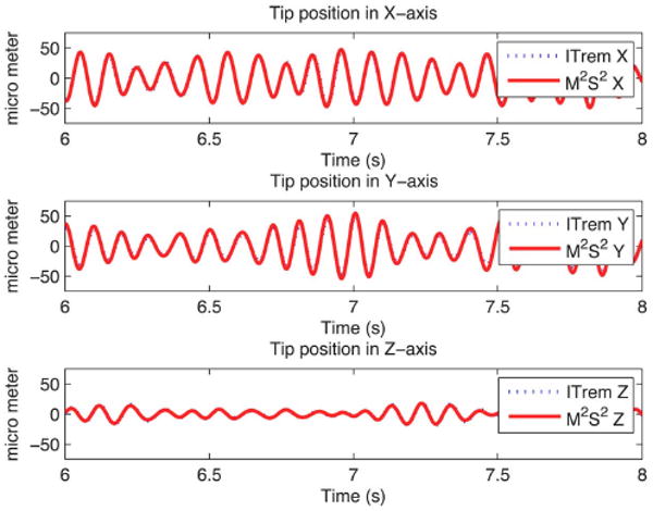
Plots of comparison of position calculated from ITrem and that measured from M2S2.
Experiment results for sensing evaluation of ITrem are shown in Table I. The values shown are average values of the four trials. RMS (μm) and RMS (mm/s2), respectively, are root mean squared values of positions and accelerations of the tip due to tremor obtained from M2S2. RMSE (μm) and RMSE (mm/s2) were obtained by, respectively, subtracting the ground-truth positions and accelerations from the calculated positions and accelerations of the tip due to tremor obtained from ITrem. Positions and accelerations of the tip due to tremor obtained from M2S2 were used as ground-truth positions and accelerations, respectively.
TABLE I. Experiment Results for Sensing Evaluation of ITrem.
| X axis | Y axis | Z axis | |
| RMS (μm) | 17.37 | 17.84 | 9.87 |
| RMS (mm/s2) | 70.74 | 72.92 | 36.15 |
| RMSE (μm) | 2.44 | 2.52 | 1.04 |
| RMSE (mm/s2) | 13.09 | 10.95 | 4.56 |
| Position accuracy (%) | 86.59 | 84.97 | 89.79 |
| Acceleration accuracy (%) | 81.75 | 84.87 | 87.41 |
Sensing accuracies of ITrem were obtained as follows:
V. Discussion
The comparison in Fig. 11 shows that the formulae in (14) and (15) are valid although there are some errors. The errors are probably due to the accuracy of the M2S2 and the noise crept into the acceleration obtained from double-differentiation of the measured ball position by M2S2.
Plots in Fig. 13 and accuracies in Table I show that the kinematic formulae (23)–(25) are correct although there are some errors. The amounts of sensing errors of the tip acceleration shown in Table I are more than the maximum value of 8 mm/s2 discussed in Section III. The errors might have resulted from the combined errors of the inaccurate positioning and orientation of the accelerometers, inaccurate measurement of the distance from the tip to an accelerometer, noises in the accelerometer outputs, accuracy and resolution of the measurement of the ball position by M2S2. The positioning and orientation errors of the accelerometers can be known by using high precision rotation and translation stages and they can be corrected. However, since the stages were not available to the authors when this research was carried out, these errors could not be identified and eliminated. That means the errors could have been reduced.
Since the sensing unit cannot provide angular acceleration about ZB axis, acceleration component in ZB axis at locations which are not on the instrument axis cannot be calculated. This might restrict the use of the proposed sensing unit with some unusual tools whose contact point with the target does not lie on the instrument axis.
Many applications do not require the instrument to be equipped with those unusual tools. For example, cells manipulation, injection of liquid medicine into a vessel, manual soldering of surface-mount electronic components, etc., require the instrument to be attached with needles or needle-like parts at the center of the instrument's distal end. In these applications, one of the goals is to hit the target accurately with the tip of the needle or needle-like part. In these applications, αz is not required and our proposed sensing design should be used for avoiding problems associated with bulkiness and heaviness of the instrument.
Except for redundant components, the fewer the components an instrument has, the smaller the probability of the instrument being failure and hence the more reliable it is. Our proposed placement design employs fewer number of accelerometers comparing to the previous designs [4], [10], and hence it can be considered more reliable.
VI. Conclusion
A compact design of placement of accelerometers in an active tremor compensation instrument has been proposed. Angular acceleration formulae derived and the kinematic formulae to obtain the tip motion are validated with experiments. The proposed design is superior in terms of ergonomics, and reliability.
Acknowledgments
This work was supported in part by the Science and Engineering Research Council (SERC) (SERC Public Funding under Grant 052 101 0017, and in part by the Biomedical Research Council (BMRC) under BMRC Grant 07/1/22/19/538 of the Agency for Science, Technology and Research (A * STAR), Singapore. The associate editor coordinating the review of this paper and approving it for publication was Prof. Paul Regtien.
Biographies

Win Tun Latt (S'08) received the B.E. degree in electronics from Yangon Technological University, Myanmar, in 2000, and the M.Sc. degree in biomedical engineering from Nanyang Technological University, Singapore, in 2004. He won a gold medal in Singapore Robotics Games 2005. He is currently working towards the Ph.D. degree in biomedical robotics at Nanyang Technological University, Singapore.
His research interests include sensing systems, signal processing, medical robotics, and mechatronics.

U-Xuan Tan (S'07) received the B.Eng. degree in mechanical and aerospace engineering from the Nanyang Technological University, Singapore, in 2005. He is currently working towards the Ph.D. degree at Nanyang Technological University, Singapore.
His research interests include mechatronics, control systems, smart materials, sensing systems, medical robotics, rehabilitative technology, mechanism design, kinematics, and signal processing.

Cheng Yap Shee received the B.Eng. and M.Eng. degrees in mechanical and production engineering from the Nanyang Technological University, Singapore, in 1997 and 1999, respectively.
He has been a Research Associate with the Biorobotics Group, Nanyang Technolgoical University, since 2005. His research interests span the areas of cellular automata and robotics.

Cameron N. Riviere (S'94–M'96) received the B.S. degree in aerospace engineering and ocean engineering from the Virginia Polytechnic Institute and State University, Blacksburg, in 1989 and the Ph.D. degree in mechanical engineering from The Johns Hopkins University, Baltimore, MD, in 1995.
Since 1995, he has been with the Robotics Institute, Carnegie Mellon University, Pittsburgh, PA, where he is presently an Associate Research Professor and the Director of the Medical Instrumentation Laboratory. He is also an adjunct faculty member of the Department of Rehabilitation Science and Technology, University of Pittsburgh. His research interests include medical robotics, control systems, signal processing, learning algorithms, and biomedical applications of human-machine interfaces.
Dr. Riviere was Guest Editor of the Special Issue on Medical Robotics of the Proceedings of the IEEE in September 2006.

Wei Tech Ang (S'98–M'04) received the B.Eng. and M.Eng. degrees in mechanical and production engineering from the Nanyang Technological University, Singapore, in 1997 and 1999, respectively, and the Ph.D. degree in robotics from Carnegie Mellon University, Pittsburgh, PA, in 2004.
He has been an Assistant Professor at the School of Mechanical and Aerospace Engineering, Nanyang Technological University, since 2004. His research interests include sensing and sensor, actuators, medical robotics, rehabilitative and assistive technology, mechanism design, kinematics, signal processing, and learning algorithms.
Contributor Information
Win Tun Latt, Email: wintunlatt@ntu.edu.sg, School of Mechanical and Aerospace Engineering, Nanyang Technological University, Singapore.
U-Xuan Tan, School of Mechanical and Aerospace Engineering, Nanyang Technological University, Singapore.
Cheng Yap Shee, School of Mechanical and Aerospace Engineering, Nanyang Technological University, Singapore.
Cameron N. Riviere, Email: camr@ri.cmu.edu, Robotics Institute, Carnegie Mellon University, Pittsburgh, PA 15213 USA.
Wei Tech Ang, School of Mechanical and Aerospace Engineering, Nanyang Technological University, Singapore.
References
- 1.Das H, Zak H, Johnson J, Crouch J, Frambach D. Evaluation of a telerobotic system to assist surgeons in microsurgery. Comput Aided Surg. 1999;4:15–25. doi: 10.1002/(SICI)1097-0150(1999)4:1<15::AID-IGS2>3.0.CO;2-0. [DOI] [PubMed] [Google Scholar]
- 2.Taylor R, et al. A steady-hand robotic system for microsurgical augmentation. Int J Robot Res. 1999;18:1201–1210. [Google Scholar]
- 3.Ang WT, Riviere CN, Khosla PK. Design and implementation of active error canceling in a hand-held microsurgical instrument. Proc. IEEE/RSJ Intl. Conf. Intell. Robot. Syst.; HI. 2001; pp. 1106–1111. [Google Scholar]
- 4.Ang WT, Khosla PK, Rivere CN. Design of all-accelerometer inertial measurement unit for tremor sensing in hand-held microsurgical instrument. Proc. IEEE Int. Conf. Robot. Autom.; Taipei, Taiwan. Sep. 14–19, 2003; pp. 1781–1786. [Google Scholar]
- 5.Ang WT. Doctoral. Robotics Inst., CMU; Pittsburgh, PA: 2004. Active tremor compensation in handheld instrument for microsurgery. [Google Scholar]
- 6.Chen IH, Lee SC, DeBra DB. Gyroscope free strapdown inertial measurement unit by six linear accelerometers. J Guidance, Control, and Dynamics. 1994 Mar.–Apr.1.17(2):286–290. [Google Scholar]
- 7.Zappa B, Legnani G, Bogert AJ, Adamini R. On the number and placement of accelerometers for angular velocity and acceleration determination. J Dynamic Syst, Measure, Control. 2001 Sep.123:552–553. [Google Scholar]
- 8.Wang Q, Ding M, Zhao P. A new scheme of non-gyro inertial measurement unit for estimating angular velocity. Proc. 29th Annu. Conf. IEEE Ind. Electron. Soc.; Nov. 2–6, 2003; pp. 1564–1567. [Google Scholar]
- 9.Tan CW, Park S. Design of accelerometer-based inertial navigation systems. IEEE Trans Instrum Measure. 2005 Dec.54:2520–2530. [Google Scholar]
- 10.Latt WT, Tan UX, Widjaja F, Ang WT. Placement of accelerometers in a hand-held active tremor compensation instrument for high angular sensing resolution. Proc. IEEE Int. Conf Robot. Biomimetics; Bangkok, Thailand. Feb. 22–25, 2009; pp. 263–268. [Google Scholar]
- 11.Patkin M. Ergonomics applied to the practice of microsurgery. Aust N Z J Surg. 1977 Jun.47:320–329. doi: 10.1111/j.1445-2197.1977.tb04297.x. [DOI] [PubMed] [Google Scholar]
- 12.Latt WT, Tan UX, Veluvolu KC, Shee CY, Ang WT. Physiological tremor sensing using only accelerometers for real-time compensation. Proc. IEEE Int. Conf. Robot. Biomimetics; Bangkok, Thailand. Feb. 22–25, 2009; pp. 474–479. [Google Scholar]
- 13.Latt WT, Tan UX, Widjaja F, Shee CY, Ang WT. A study of a hand-held instrument's angular motion due to physiological tremor in micromanipulation tasks. Proc. 30th Annu. Int. Conf. IEEE Eng. Med. Biol. Soc.; Vancouver, BC, Canada. Aug. 20–24,2008; pp. 1952–1955. [DOI] [PubMed] [Google Scholar]
- 14.Win TL, Tan UX, Shee CY, Ang WT. Design and calibration of an optical micro motion sensing system for micromanipulation tasks. Proc. IEEE Int. Conf. Robot. Autom.; Roma, Italy. Apr. 2007; pp. 3383–3388. [Google Scholar]
- 15.Latt WT, Tan UX, Widjaja F, Shee CY, Ang WT. Handling light disturbances in a micro motion sensing system and investigation of the system performance. Proc. IEEE Int. Conf. Biomed. Robot. Biomech.; Scottsdale, AZ. Oct. 2008; pp. 463–468. [Google Scholar]


