Abstract
Cell-laden microscale hydrogels (microgels) can be used as tissue building blocks and assembled to create 3D tissue constructs with well-defined micro-architecture. In this paper, we present a bottom-up approach to achieve microgel assembly on a patterned surface. Driven by surface tension, the hydrophilic microgels can be assembled into well-defined shapes on a glass surface patterned with hydrophobic and hydrophilic regions. We found that the cuboidic microgels (~100-200 μm in width) could self-assemble into defined shapes with high fidelity to the surface patterns. The microgel assembly process was improved by increasing the hydrophilicity of the microgels and reducing the surface tension of the surrounding solution. The assembled microgels were stabilized by a secondary crosslinking step. Assembled microgels containing cells stained with different dyes were fabricated to demonstrate the application of this approach for engineering microscale tissue constructs containing multiple cell types. This bottom-up approach enables rapid fabrication of cell-laden microgel assemblies with pre-defined geometrical and biological features, which is easily scalable and can be potentially used in microscale tissue engineering applications.
Keywords: hydrogel, bottom-up, directed assembly, tissue engineering
Introduction
Microgels are microscale hydrogels fabricated by the merger of microscale technologies and hydrogel chemistry(Khademhosseini and Langer 2007). Microgels exhibit many desirable properties for tissue engineering applications, such as tunable geometries(Suh et al. 2006), mechanical strength and biodegradability and resemble the natural extracellular matrix (ECM) for cell encapsulation at tissue densities(Brigham et al. 2008). Therefore, cell-laden microgels may be used as building blocks to fabricate 3D tissue constructs that mimic the in vivo tissue structures by containing repeating functional units that make up most tissues (i.e. islet, nephron, or sinusoid)(Costanzo 2006). The bottom-up assembly of cell-laden microgels has been gaining increased attention in tissue engineering research, with numerous approaches developed including random assembly(McGuigan and Sefton 2006), manual manipulation(Yeh et al. 2006), multi-layer photo-patterning(Liu Tsang et al. 2007), microfluidic-directed assembly(Chung et al. 2008) and hydrophobic interactions(Du et al. 2008). Random assembly of microgel modules is rapid and simple, but lacks the control over the final structure of the hydrogel aggregate. To assemble these microgels, manual manipulations may be used, but this approach is relatively slow and non-scalable for fabrication of large tissues. Multi-layer photo-patterning and microfluidic-directed assembly can also be used to create highly sophisticated microgel assembly architectures, but long operational times and complex equipments are usually required. Recently, we have developed a directed-assembly approach of cell-laden microgels in a two-phase oil-aqueous solution reactor(Du et al. 2008). The assembly approach requires the use of mineral oil or other hydrophobic organic solvents, which limit its application for sensitive cells. Therefore, the development of alternative approaches that can be used to assemble microgels without the need for fluidic devices or organic solvents may be of benefit for directed assembly of cell-laden hydrogels.
Here, we achieved directed-assembly of cell-laden microgels into tissue sheets on surfaces patterned with hydrophobic and hydrophilic regions(Lauer et al. 2001),(Kokkoli and Zukoski 2000). We hypothesized that the hydrophilic microgels would have a tendency to assemble within patterned aqueous droplets(Suh 2006), which were confined inside the hydrophilic patterns. Using this process we assembled microgels on surfaces and regulated the architecture of the microgel assembly by controlling the size and shape of the patterns on the surface. To stabilize the assembled microgels, a secondary crosslinking reaction was used to encapsulate the assembled microgels into a bulk hydrogel material. The stabilized assembled microgels could be readily harvested from the surface as multi-cellular tissue constructs. This bottom-up approach enables rapid and scalable fabrication of cell-laden microgel assemblies with pre-defined geometrical and biological features, which can be potentially used for microscale tissue engineering applications.
Materials and Methods
Materials
All reagents were obtained from Sigma Aldrich, unless noted otherwise.
Patterning of glass slides by micro contact printing (Fig. 1A)
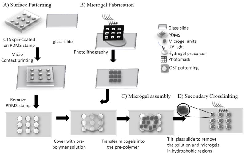
Fig. 1. Schematic diagram of the procedures involved in the surface-directed assembly of microgels.

(A) generating hydrophobic regions of OTS patterns on a hydrophilic glass by microcontact printing; (B) generating PEG-DA microgel building blocks by photolithography; (C) directed-assembly of the microgels on the hydrophilic patterns; (D) stabilization of the microgel assemblies by secondary crosslinking.
To pattern the substrate with hydrophobic and hydrophilic regions, we followed a slightly modified protocol developed by Xia et. al.(Xia 1995) In brief, glass slides were first treated with Piranha solution (70% sulfuric acid/30% hydrogen peroxide) for 30min at 80°C and then cleaned with distilled water 3 times. Polydimethylsiloxane (PDMS, Sylgard) stamps with defined patternings (i.e. square, line and the letters of ‘MIT’) were made by soft-lithography(Moeller et al. 2008). To pattern the slides, a PDMS stamp was spin-coated with a 1% octadecyltrichlorosilane (OTS) solution dissolved in hexane at 3000rpm for 30s and gently pressed onto the treated glass slide. The OTS pattern was transferred from the PDMS stamps onto the glass surface by contacting for 2min. The regions that were treated with OTS became hydrophobic with a contact angle of around 112°C(Pozzato et al. 2006).
Fabrication of microgels by photolithography (Fig. 1B)(Du et al. 2008)
Briefly, the PEG hydrogel precursor solution was made by mixing 59-89% (w/w) Dulbecco’s Phosphate Buffered Saline (DPBS, Gibco), 1% (w/w) Irgacure 2959 (I2959, CIBA chemicals) and 10-40% (w/w) polyethylene glycol diacrylate (PEG-DA, 575, 2000 or 4000, Monomer-Polymer & Dajac Labs) or polyethylene glycol dimethacrylate (PEG-DMA, 1000, Polysciences). 30μl of PEG precursor solution was pipetted onto an 18×18mm glass cover slip (No. 1, 150μm thick, VWR International). Another two slides were placed on the opposite sides of the cover slip as spacers and a fourth slide was placed on top to form an even layer of PEG precursor solution with a thickness of 150μm. Alternatively, to form 50μm gel, two pieces of invisible tape (Staples, MA) were used instead of glass slide as spacer to achieve a thickness of 50μm. A photomask (with square patterns of 50×50, 100×100, 200×200 and 400×400μm) was then placed on top of the setup, through which UV light (360-480nm, 12.4mW/cm2) was applied to form the PEG microgels by photo-crosslinking the precursor solution.
Assembling microgels on micro patterned glass substrates (Fig. 1C)
A micro-patterned glass slide was coated with 550μl of a solution of either DPBS or DPBS with 0.5% Tween 20 or PEG precursor solution. Microgels (3000 pieces/ml) were transferred into this solution by a 27G needle (BD, NJ). The microgels were allowed to settle for 3min before the glass slide was tilted to have the microgels attach to the patterns. To visualize the microgels, phase images were captured by an inverted light microscopy (Nikon, USA). To quantify the microgel assembly on the patterned regions, the total number of microgels within a microgel assembly was manually counted. The obtained numbers were used to calculate the total area of microgels (number of microgels times the cross-sectional area of an individual microgel). The area covered by microgels (AC) was obtained by dividing the total area of microgels with the area of the underlining pattern (1mm2).
Secondary crosslinking of the assembled microgels
To stabilize the microgel assembly, a precursor solution of PEGDA-2000 was used instead of DPBS as the bulk solution. After the patternings containing assembled microgels and bulk precursor solution were formed on the glass slide, a secondary UV-crosslinking (exposure for 20s) was applied to encapsulate the assembled microgels in the bulk hydrogel. When stabilized, the bulk hydrogel sheet containing the encapsulated microgels can be easily harvested with a sharp blade that detaches the hydrogel sheet from the bottom glass slide at the contact region.
Generating cell-laden microgel co-cultures
NIH-3T3 mouse fibroblast cells were cultured in DMEM supplemented with 10% Fetal Bovine Serum (FBS) and penicillin-streptomycin (Gibco) and kept in a 95%O2/5%CO2 humidified 37°C incubator. Cells were harvested by using trypsin and divided into two sets. One set of cells was stained with PKH26 (Gabler et al.) and another set was stained with CellTrace™ CFSE (green, Invitrogen) (Lee et al. 2000; Rodel et al. 2005). The red-labeled cells were resuspended in the prepolymer solution (20% PEG-DA 1000) in a density of 107cells/ml and then encapsulated in the microgel building blocks while the green-labeled cells were resuspended in the bulk precursor solution (12% PEG-DA 1000) in a density of 107cells/ml and then encapsulated in the bulk hydrogel. Cell viability was characterized by incubating cells with live/dead dyes (2μL calcein AM and 0.5μL ethidium homodimer-1, Molecular Probes, California) in 1mL DPBS for 10 min.
Statistical methods
Data from at least three independent experiments were analyzed and values were represented as mean±standard error of means. The Student t-test was used to analyze the statistical significance of the data. Values with a p value less than 0.05 were considered statistically significant.
Results and Discussion
We have achieved the directed-assembly of the hydrophilic microgel building blocks on a patterned glass surface with patterned hydrophobicity. The surface-directed assembly process can be summarized in three steps (Fig. 1A-C): 1)) micropatterning the surface of the hydrophilic glass slide using hydrophobic OTS solution(Benor 2007; Xia 1995); 2) fabricating PEG microgel building blocks by photolithography; 3) directing the assembly of the microgels in the hydrophilic regions of the patterned glass slide. Since hydrophilic liquid tends to remain on the hydrophilic regions, we anticipated that the liquid droplets would be confined by the OTS-inked hydrophobic regions. Furthermore, the hydrophilic microgels will remain submersed in aqueous solution (i.e. PBS or crosslinking solution), thereby self-assembling into defined shapes.
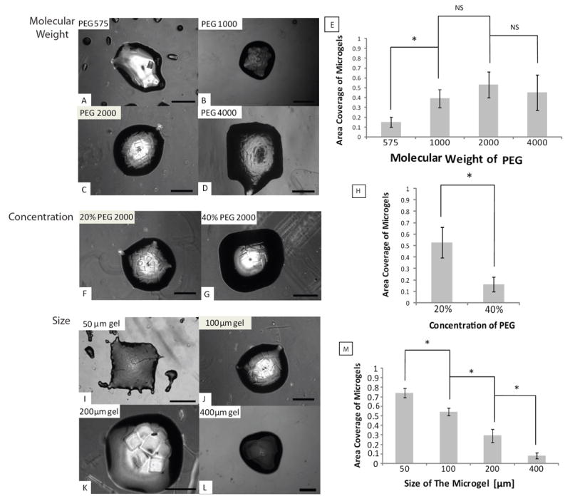
As shown in Fig. 2, PEG microgels self-assembled within the PBS solution, which was confined by the hydrophobic patterns (1×1mm square) on the glass surface. To optimize the surface-directed assembly approach, we investigated the effects of microgel properties, microgel size and the addition of surfactant on the final microgel assemblies. We first tested the microgel building blocks (100×100×150μm) made from PEG with different molecular weights (PEG 575, 1000, 2000 and 4000). Molecular weight is known to affect the hydrophilicity of the microgels and higher molecular weight PEG is more hydrophilic than lower molecular weight PEG due to an increased ratio of hydroxyl groups within the polymer. As shown in Fig. 2 A-E, the less hydrophilic PEG 575 microgels did not assemble well within the hydrophilic patterns (area coverage (AC) < 20%) with some non-specific attachment in the hydrophobic regions, while the more hydrophilic PEG 1000, 2000 and 4000 microgels assembled within the hydrophilic patterns with high fidelity (AC~50%). Based on these results, PEG 2000 was chosen to test the effect of precursor concentration on the microgel assembly. As shown in Fig. 2 F-H, 20% PEG microgels (100×100×150μm) were able to assemble with higher pattern fidelity to underlying substrate than the 40% PEG microgels (100×100×150m) (AC<20%). Although further decreasing the concentration of PEG is expected to improve the fidelity of assembly to the patternings, we were unable to make well-formed microgels with PEG concentration less than 20% by using the current photolithography setup. These results indicate that the molecular weight and concentration of the PEG affect the chemical (i.e. hydrophilicity, electrostatic) and physical properties (i.e. density and rigidity) of the microgels and the resulting assembly process. Several factors can be potentially attributed to the differences between 40% and 20% PEG microgels: 1) with lower water content, 40% PEG microgels are less hydrophilic compared to 20% PEG microgels; 2) with more polymer content, 40% PEG microgels are heavier than the 20% PEG microgels. Therefore, 40% PEG microgels tends to fall faster to the bottom surface and exhibit less mobility in the bulk solution during the assembly procedure causing less fidelity to the surface patternings.
Fig. 2. Optimization of the surface-directed assembly of microgels.

(A-D) effect of molecular weight of the PEG-DA (575-4000); (F-G) effect of the concentration of PEG-DA hydrogel precursor solution (20%, 40%); (I-L) effect of the microgel size (from 50-400μm) on the assembly process; (E, J, M) quantitative analysis of the effects of the MW, concentration and size of PEG-DA microgel on the assembly; Scale bars are 400μm.
We then investigated the effects of the microgel dimensions on the final assembly by varying the size of microgels (Fig. 2 I-M). We saw that smaller microgels (50×50×50, 100×100×150μm) assembled well within the patterns (AC~70% and AC~50%). However, as the size of microgel increased (200×200×150 and 400×400×150μm), the fidelity of the assembly to the patterns decreased (AC~30% and AC~10%), with fewer microgels assembling within the hydrophilic regions. This may be due to the hydrodynamic forces becoming more dominant over the surface tension as the microgels become larger. Also it was observed that the microgels did not fully cover the patterning region of the bulk solution upon assembly. This may be due to the spatial hindrance between the mesoscale microgel building blocks as the assembled patterns for 50×50×50μm microgels follows the underlining patterns more precisely than its larger counterparts. Given that most of the tissue building blocks are within the range of hundreds of microns, microgels with the size of 100×100×150μm were chosen to conduct the following studies.
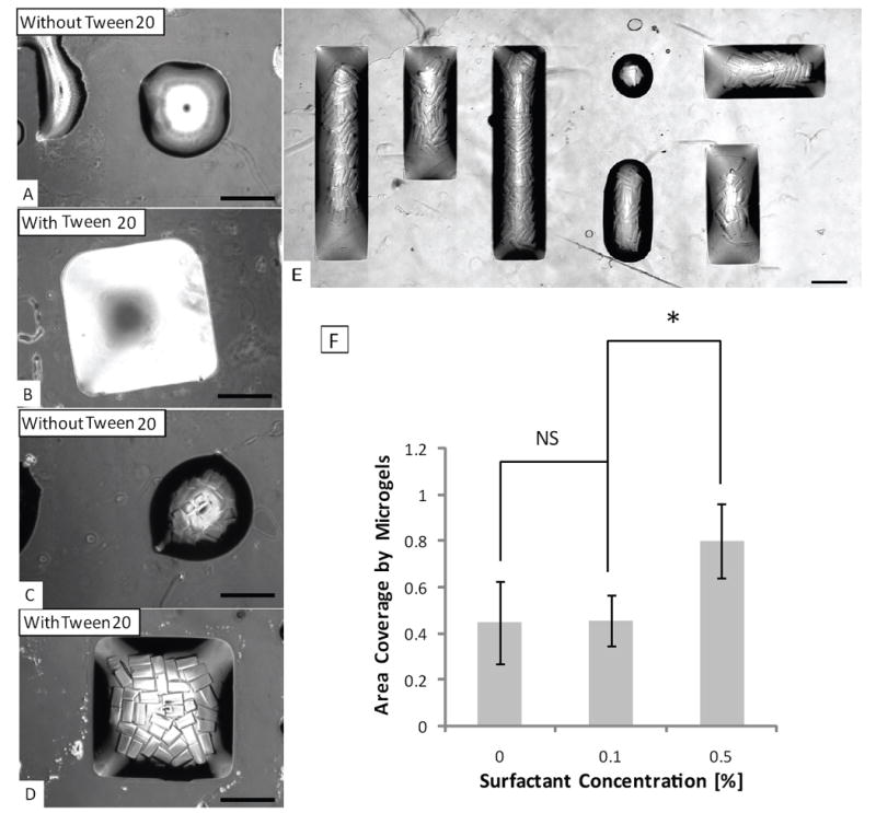
To enhance the pattern fidelity of the microscale aqueous droplets, we investigated the effects of the addition of a surfactant. In conditions without surfactants, the microgel assemblies appeared circular at the corners, despite of the fact that underlying hydrophilic patterns were square. This loss of fidelity to the pattern shape is likely due to the surface tension of aqueous solution, which tends to minimize the air-water interface and confines the shape of the patterned drops to be spherical. To improve the resolution of the microgel assembly patterns, surfactant (Tween 20) was added to the bulk DPBS solution at volume ratios of 0.1% and 0.5% to reduce the surface tension. After the addition of the surfactant, we observed that both the bulk solution and PEG 4000 microgel assembly exhibit better fidelity to the underlying square patterns (Fig. 3). Addition of 0.5% surfactant significantly improved the microgel assembly (AC~80%) compared with 0.1% and no surfactant (AC~45%). To test the feasibility of this procedure for generating more complex shapes, a ‘MIT’ logo made from assembled microgels was also fabricated, which demonstrate the diverse shapes of the microgel assembly achieved by this approach. To apply to cell-laden microgel assembly, non-toxic surfactant such as pyridinium compounds(van der Woude et al. 1997) can be used to replace the toxic Tween 20.
Fig. 3. Effect of surfactant on the microgel assembly process.

Patterning of precursor solution with (A) and without (B) surfactant; and assembled microgels in the precursor solution with (C) and without surfactant (D); (E) microgel assembly on ‘MIT’ pattern with the addition of surfactant; (Due to the large size of the ‘MIT’ pattern, image of the letter ‘M’, ‘I’, ‘T’ was taken individually and merged by Photoshop); (F) quantitative analysis of the effects of the 0.1% and 0.5% surfactant on the microgel assembly. Scale bars are 400μm.
It is desirable to harvest the assembled microgel structures as a whole for subsequent applications. Thus, a secondary UV-crosslinking was adopted to stabilize the microgel assembly, by replacing the the DPBS bulk solution with the PEG precursor solution. By using these conditions, a secondary UV exposure encapsulated the microgels in the polymerized bulk hydrogel. In this way, the microgel assembly could be stabilized after incubation with DPBS (Fig. 4A-B). Interestingly, by varying the concentration of the bulk PEG precursor solution, the mechanical properties of the bulk hydrogel could be modulated as indicated by the change of morphology of the bulk hydrogel. By using 8% PEG as the bulk solution (with an Elastic Modulus about 0.2Mpa)(Gabler et al. 2009), microgels were tightly assembled with one other after a secondary crosslinking with no visible bulk hydrogel, whereas for the 12% PEG (with an Elastic Modulus about 0.5Mpa)(Gabler et al. 2009), the secondary cross-linked bulk hydrogel was clearly visible to surround the assembled microgels (Fig. 4B-C).
Fig. 4. Secondary crosslinking to encapsulate the assembled microgels in a bulk hydrogel with defined architecture.

(A) dissociated microgels in water without secondary crosslinking; (B) encapsulated microgels in bulk hydrogel from 8% PEG-DA precursor solution (without visible formation of bulk hydrogel) after secondary crosslinking in water; (C) encapsulated microgels in bulk hydrogel from 12% PEG-DA precursor solution (with visible bulk hydrogel formation) after secondary crosslinking in water; Scale bars are 400μm.
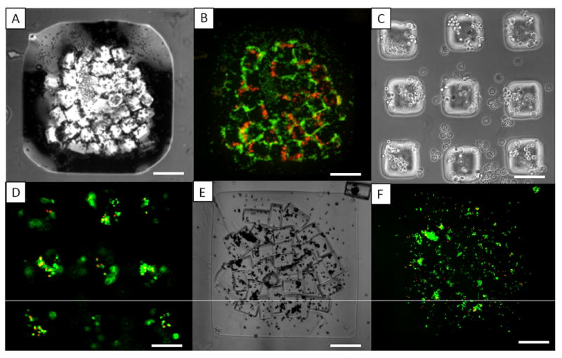
Finally, to demonstrate that this approach can be used to engineer microscale tissue constructs containing multiple cell types, assembled microgels containing cells stained with different dyes were fabricated. NIH 3T3 fibroblasts labeled fluorescently with red dye (PKH26) were encapsulated in the microgel building blocks, which were assembled within the bulk hydrogel precursor solution containing green-labeled (CFSE) NIH 3T3 cells. After secondary crosslinking, the co-culture assemblies that contained cells stained red and green respectively were constructed (Fig. 5A-B). Due to the usage of biological fluids and ambient temperature, this directed-assembly process is expected to be amicable for maintaining cell viability. Indeed, NIH 3T3 cells encapsulated in microgel assembly exhibited ~90% viability 24h after assembly (Fig. 5E-F), which is comparable to the viability of cells encapsulated in individual microgels (Fig. 5C-D). The microscale tissue constructs can be used as a ‘3D co-culture system’ in which both cell types are physically separated and cultured in a 3D microenvironment tailored for specific requirements. An exemplary co-culture system can comprise hepatocytes in microgels (such as collagen microgels for maintaining the liver-specific functions) as functional cells and fibroblast in the bulk hydrogel (such as PEG hydrogel to provide mechanical support) as supporting cells.
Fig. 5. Assembling cell-laden microgels in shaped-defined bulk hydrogel.

(A-B): phase and fluorescence image of the microgel assembles with the red labeled cells (encapsulated in microgels) and the green labeled cells (encapsulated in bulk hydrogel); (C-F): morphology and viability staining of the cell-laden microgel before assembly (C,D) and after assembly in patterned bulk hydrogel (E,F) after 24h culture; Scale bars for (A,B, E, F) are 400μm, for (C,D) are 100μm.
The microgel assemblies obtained using the current approach are essentially ‘sheet-like’ tissue constructs confined to 2D patterns on the substrate. The thickness of the tissue sheet is limited by the height of the bulk solution droplet that can be supported by the underlining hydrophilic patterns. 3D tissue constructs containing various layers of these tissue sheets can be potentially obtained by a ‘secondary assembly’ to stack the tissue sheets manually or in a ‘two-phase’ reactor as we reported previously(Du et al. 2008). Also the shapes of tissue sheet confined to the hydrophilic patterns are demonstrated as simple squares and rectangles in this report and it is more challenging to create tissue construct with complicate shapes. Smaller microgel building blocks (~50μm) are expected to greatly improve the resolution of the microgel assemblies confined by the underlining patterns. Furthermore, by varying the geometric design of the microgel building blocks (i.e. lock-and key), it is envisioned that microengineered tissue sheets with pre-defined microarchitectures and biological components can be fabricated in a rapid and scalable manner that mimic the native tissue geometry and functionalities.
Conclusions
We developed a bottom-up approach for microgel assembly directed by surface patterning. Hydrophilic microgels were self-assembled into well-controlled shapes in the crosslinking solution, which was confined in the hydrophilic regions on the glass surface patterned with the hydrophobic Octadecyltrichlorosilane. By a secondary crosslinking approach, the assembled microgels were encapsulated in the bulk hydrogel with defined shapes, which could be harvested from the glass surface as a tissue sheet. We optimized the surface-directed assembly process for microgels and demonstrated its applications for a co-culture system with two differently labeled cells encapsulated in microgels and bulk hydrogel respectively. These cell-laden assembled microgel structures can be potentially useful for rapidly generating tissue sheets with engineered microarchitectures in a scalable manner for tissue engineering applications.
Acknowledgments
This research has been funded by the NIH (HL092836, DE019024), and the Institute for Soldier Nanotechnology. Yanan Du was sponsored by the U.S. Army Construction Engineering Research Laboratory, Engineering Research and Development Center (USACERL/ERDC).
Footnotes
Author contributions: Y.D., E.L., M.G. and A.K. designed the research; Y.D., M.G. and E.L. performed the research; Y.D., E.L., M.G. and M.K.V. analyzed the data; and Y.D., E.L., M.K.V and A.K. wrote the paper.
References
- Benor A, Hoppe A, Wagner V, Knipp D. Microcontact printing and selective surface dewetting for large area electronic applications. Thin Solid Films. 2007;515:7679–7682. [Google Scholar]
- Brigham MD, Bick A, Lo E, Bendali A, Burdick JA, Khademhosseini A. Mechanically Robust and Bioadhesive Collagen and Photocrosslinkable Hyaluronic Acid Semi-Interpenetrating Networks. Tissue Eng Part A. 2008;15(7):1645–53. doi: 10.1089/ten.tea.2008.0441. [DOI] [PMC free article] [PubMed] [Google Scholar]
- Chung SE, Park W, Shin S, Lee SA, Kwon S. Guided and fluidic self-assembly of microstructures using railed microfluidic channels. Nat Mater. 2008;7(7):581–7. doi: 10.1038/nmat2208. [DOI] [PubMed] [Google Scholar]
- Costanzo L. Physiology. Philadelphia: Saunders; 2006. [Google Scholar]
- Du Y, Lo E, Ali S, Khademhosseini A. Directed assembly of cell-laden microgels for fabrication of 3D tissue constructs. Proc Natl Acad Sci U S A. 2008;105(28):9522–7. doi: 10.1073/pnas.0801866105. [DOI] [PMC free article] [PubMed] [Google Scholar]
- Gabler S, Stampfl J, Koch T, Seidler S, Schuller G, Redl H, Juras V, Trattnig S, Weidisch R. Determination of the viscoelastic properties of hydrogels based on polyethylene glycol diacrylate (PEG-DA) and human articular cartilage. International Journal of Materials Engineering Innovation. 2009;1(1):3–20. [Google Scholar]
- Khademhosseini A, Langer R. Microengineered hydrogels for tissue engineering. Biomaterials. 2007;28(34):5087–92. doi: 10.1016/j.biomaterials.2007.07.021. [DOI] [PubMed] [Google Scholar]
- Kokkoli E, Zukoski CF. Interaction Forces between Hydrophobic and Hydrophilic Self-Assembled Monolayers. J Colloid Interface Sci. 2000;230(1):176–180. doi: 10.1006/jcis.2000.7089. [DOI] [PubMed] [Google Scholar]
- Lauer L, Klein C, Offenhausser A. Spot compliant neuronal networks by structure optimized micro-contact printing. Biomaterials. 2001;22(13):1925–32. doi: 10.1016/s0142-9612(00)00379-3. [DOI] [PubMed] [Google Scholar]
- Lee GM, Fong S, Francis K, Oh DJ, Palsson BO. In situ labeling of adherent cells with PKH26. In Vitro Cell Dev Biol Anim. 2000;36(1):4–6. doi: 10.1290/1071-2690(2000)036<0004:ISLOAC>2.0.CO;2. [DOI] [PubMed] [Google Scholar]
- Liu Tsang V, Chen AA, Cho LM, Jadin KD, Sah RL, DeLong S, West JL, Bhatia SN. Fabrication of 3D hepatic tissues by additive photopatterning of cellular hydrogels. Faseb J. 2007;21(3):790–801. doi: 10.1096/fj.06-7117com. [DOI] [PubMed] [Google Scholar]
- McGuigan AP, Sefton MV. Vascularized organoid engineered by modular assembly enables blood perfusion. Proc Natl Acad Sci U S A. 2006;103(31):11461–6. doi: 10.1073/pnas.0602740103. [DOI] [PMC free article] [PubMed] [Google Scholar]
- Moeller HC, Mian MK, Shrivastava S, Chung BG, Khademhosseini A. A microwell array system for stem cell culture. Biomaterials. 2008;29(6):752–63. doi: 10.1016/j.biomaterials.2007.10.030. [DOI] [PMC free article] [PubMed] [Google Scholar]
- Pozzato A, Zilio SD, Fois G, Vendramin D, Mistura G, Belotti M, Chen Y, Natali M. Superhydrophobic surfaces fabricated by nanoimprint lithography. Microelectronic Engineering. 2006;83(49):884–888. [Google Scholar]
- Rodel F, Franz S, Sheriff A, Gaipl U, Heyder P, Hildebrandt G, Schultze-Mosgau S, Voll RE, Herrmann M. The CFSE distribution assay is a powerful technique for the analysis of radiation-induced cell death and survival on a single-cell level. Strahlenther Onkol. 2005;181(7):456–62. doi: 10.1007/s00066-005-1361-3. [DOI] [PubMed] [Google Scholar]
- Suh KY. Surface-tension-driven patterning: combining tailored physical self-organization with microfabrication methods. Small. 2006;2(7):832–4. doi: 10.1002/smll.200600121. [DOI] [PubMed] [Google Scholar]
- Suh KY, Khademhosseini A, Jon S, Langer R. Direct confinement of individual viruses within polyethylene glycol (PEG) nanowells. Nano Lett. 2006;6(6):1196–201. doi: 10.1021/nl060571a. [DOI] [PubMed] [Google Scholar]
- van der Woude I, Wagenaar A, Meekel AA, ter Beest MB, Ruiters MH, Engberts JB, Hoekstra D. Novel pyridinium surfactants for efficient, nontoxic in vitro gene delivery. Proc Natl Acad Sci U S A. 1997;94(4):1160–5. doi: 10.1073/pnas.94.4.1160. [DOI] [PMC free article] [PubMed] [Google Scholar]
- Xia Y, Mrksich M, Kim E, Whitesides GM. Microcontact Printing of Octadecylsiloxane on the Surface of Silicon Dioxide and Its Application in Microfabrication. Journal of the American Chemical Society. 1995;117:9576–9577. [Google Scholar]
- Yeh J, Ling Y, Karp JM, Gantz J, Chandawarkar A, Eng G, Blumling J, 3rd, Langer R, Khademhosseini A. Micromolding of shape-controlled, harvestable cell-laden hydrogels. Biomaterials. 2006;27(31):5391–8. doi: 10.1016/j.biomaterials.2006.06.005. [DOI] [PubMed] [Google Scholar]


