Abstract
The high-frequency transceiver array based on the microstrip transmission line design is a promising technique for ultrahigh field magnetic resonance imaging (MRI) signal excitation and reception. However, with the increase of radio-frequency (RF) channels, the size of the ground plane in each microstrip coil element is usually not sufficient to provide a perfect ground. Consequently, the transceiver array may suffer from cable resonance, lower Q-factors, and imaging quality degradations. In this paper, we present an approach to improving the performance of microstrip transceiver arrays by introducing RF shielding outside the microstrip array and the feeding coaxial cables. This improvement reduced interactions among cables, increased resonance stability, and Q-factors, and thus improved imaging quality. An experimental method was also introduced and utilized for quantitative measurement and evaluation of RF coil resonance stability or “cable resonance” behavior.
Index Terms: Cable resonance, high field magnetic resonance imaging (MRI), microstrip transmission line resonator, radio-frequency (RF) coil, RF shielding
I. INTRODUCTION
The major advantage provided by high magnetic fields is increased nuclear magnetic resonance (NMR) sensitivity, offering improved spatial and spectral resolution [1]–[7]. For parallel imaging strategies based on multicoil arrays [8], [9], high fields are expected to improve parallel imaging performance due to the unique complex sensitivity profiles of each coil element and the increased signal-to-noise ratio (SNR) [10]–[12]. Technical challenges in designing large-size, high-frequency transceiver arrays required for the efficient excitation and detection of magnetic resonance (MR) signals in human subjects are prominent at ultrahigh fields and have become a major hindrance in the further development of ultrahigh field parallel imaging and the translation of this promising, fast, highly sensitive imaging approach for clinical use. In human ultrahigh field parallel imaging, electromagnetic coupling among array elements, degraded coil quality factors (Q-factors), B1 inhomogeneity induced by large-sized, dielectric biological samples, and difficulties in achieving the required high frequency, become pronounced. Microstrip resonator technology for radio-frequency (RF) coil array design developed recently [12]–[17] demonstrates a superior performance in quality factors, high frequency capabilities and unparalleled decoupling performance, and is capable of alleviating the technical difficulties in ultrahigh field parallel imaging. In contrast to the receive-only parallel imaging arrays commonly used at lower field strengths, transceiver arrays with independent RF amplitude and phase control on each element, capable of performing parallel excitation and B1 shimming, are necessary and have become a popular solution to high field issues of specific absorption rate (SAR), B1 inhomogeneity induced by samples and fast selective excitations [12], [18].
In microstrip arrays, the ground planes of coil array elements are usually separated to further improve their decoupling performance, especially in transceiver arrays with densely placed elements for pursuing high parallel imaging performance, and to minimize the potential eddy current problem in high field imaging. However, with the increase in number of channels or elements, the size of each ground plane is not large enough to be a perfect or “true” ground. The condition of the microstrip, an unbalanced transmission line circuit, is then not rigorously satisfied. Consequently, the transceiver array may suffer from serious “cable resonance” and lower Q-factors. When an imperfect unbalanced microstrip resonator is connected to a coaxial feeding cable, also an unbalanced transmission line circuit, the currents on the “ground” of the imperfect unbalanced microstrip resonator goes to the outer conductor of the coaxial feeding cable. The coaxial feeding cable therefore becomes a part of the resonator circuit. This makes coil resonance and impedance extremely sensitive to the environmental changes around the feeding cable. This phenomenon is conventionally called “cable resonance.” The resonance instability caused by the “cable resonance” makes it very difficult for coil tuning and matching, ultimately resulting in imaging quality degradations. Moreover, the large reflection RF power caused by the imperfect tuning and matching may greatly reduce the efficiency of MR signal excitation and reception. Symmetrical feeding [19] by inserting the tuning/matching circuit at the center of each microstrip can diminish the cable-resonance problem, improving the coil’s stability despite some difficulties in performing on-site tuning/matching. In this work we propose an approach to improving the performance of microstrip transceiver arrays by introducing an additional RF shielding outside the microstrip array and the feeding coaxial cables. The transceiver array design with this improvement reduced interactions among cables, enhanced resonance stability of each resonant element, bettered Q-factors, and thus improved imaging quality in human ultrahigh field MRI.
II. MATERIALS AND METHODS
A. RF Shield for Microstrip Coil Arrays
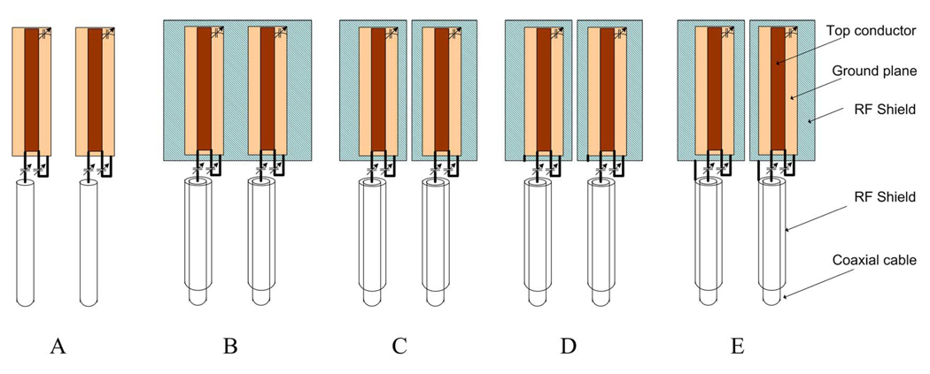
To increase the stability of microstrip coil arrays by using RF shielding, four different configurations of shielded microstrips with two elements (as shown in Fig. 1) were investigated and tested on bench. The length of the two microstrip elements was 20.0 cm while the width of the strip conductors and the ground plane were 0.63 cm and 2.54 cm, respectively. The microstrip elements were connected to 20-cm-long low noise coaxial cables (G 01130 HT, HUBER + SUHNER) via impedance matching circuits. The distance between the two coil elements was 5.0 cm. Both of the coils were matched to 50 Ω (S11 were ~−25 dB or better) and tuned to 298.1 MHz after loading them with a 17-cm-diameter sphere phantom filled with copper sulfate solution. The schematic of the unshielded microstrip setup (i.e., scheme A) is shown in Fig. 1(a). The RF shielding was added under the microstrip elements with four different configurations and also wrapped around the feeding cables. The added RF shielding was also expected to minimize the “radiation” losses (which is one of the major losses in ultra-high field MRI) caused by the nonideal ground of the microstrip. However, the introduced RF shields may also increase the magnetic field crosstalk between coil elements and hence split the resonance peaks. To investigate the appropriate shielding scheme for the microstrip coil array, scattering parameters were recorded and compared with a network analyzer (Agilent Model E5070B).
Fig. 1.
Schematic of the modifications to enhance coils’ stability. (a) Microstrip coils without RF shield, (b)–(e) microstrip coils with RF shields. (b) A whole piece of copper sheet was placed under the grounds of coils. (c) Separated copper sheets were placed under the grounds. (d) Ground of each coil was connected to the shield under it. (e) Ground of each coil was connected to the cable shield.
In Fig. 1(b) (shielding scheme B), a single-piece copper sheet with a size of 20 cm × 10 cm was placed under the coils. The gap between the ground plane and the copper sheet was approximately 1.3 cm (various gaps were also investigated). The feeding coaxial cables were wrapped with nonmagnetic copper tapes to minimize their signal losses. The length of the shielded cables was approximately 10 cm. Fig. 1(c) illustrates the same shielding scheme as shown in Fig. 1(b), but the single-piece RF shielding was replaced by two separated RF shields (i.e., scheme C). In Fig. 1(d), the ground plane of the microstrip element was connected to the RF shield beneath through a short piece of copper wire (i.e., scheme D). The last configuration is demonstrated in Fig. 1(e), in which the RF shields were connected to the cable shield instead of the ground plane of the microstrip element (i.e., shielding scheme E).
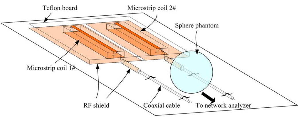
To measure the stability or “cable resonance” of the RF coils in the different shielding schemes, an experimental method was designed. The schematic of the experiment setup is illustrated in Fig. 2. Two straight-type RF coils along with their coaxial feeding cables were placed in parallel and fixed on a Teflon board. The distance or gap between the two coils was 5.0 cm. The two RF coils were tuned to the same frequency of 298.1 MHz and matched to system’s 50 Ω. A 17-cm spherical water phantom (GE Healthcare, Milwaukee, WI) was then placed 1.2-cm above the two feeding cables of the coils. To avoid the possible loading of the phantom to the coils, the phantom was positioned 30 cm away from the coils. The “cable resonance” of the RF coils was evaluated by measuring the changes in their resonance frequency and impedance matching with and without the presence of the water phantom. This method provides a reliable, quantitative approach to the RF coil “cable resonance” (or resonance stability) measurement. Q-factors, coupling between the coil elements in different shielding schemes were also measured and listed in Table I.
Fig. 2.
Method of evaluation of coil stability or “cable-resonance” behavior by measuring changes in coil’s resonance frequency and impedance caused by the interaction between a phantom and EM fields generated by the currents on the outer conductor of the feeding coaxial cables. To ensure that the frequency change and impedance change were caused only by the EM fields of cables, the phantom was placed 30 cm away from the microstrip coils so that the coils do not “see” the phantom.
TABLE I.
Comparison of Different Shielding Schemes for microstrip Coil Array
| Shielding schemes |
Stability | Q-factor | Coupling S21 (−dB) |
|
|---|---|---|---|---|
| Change in Freq (ΔMHz) |
Change in Matching (ΔdB) |
|||
| A | 0.45 | 16 | 116 | 20 |
| B | 0.15 | 8 | 107 | peak split |
| C | 0.30 | 12 | 112 | 19 |
| D | 0.15 | 9 | 124 | peak split |
| E | 0.05 | 5 | 168 | 17 |
Without using any shields [i.e., scheme A as shown in Fig. 1(a)], the stability of the microstrip coils was poor in terms of frequency shift and matching degeneration, and the loaded Q-factor was 116. Scheme B resulted in more stable resonance, but the increased coil coupling led to a resonance peak split. With separated RF shielding in scheme C, the inductive coupling between coils was low but the coil stability and Q-factor did not improve notably. In Scheme D, connecting the coil ground plane with the RF shielding also caused strong mutual coupling. Due to the split of the resonance peaks in scheme B and scheme D, the stability measurements (frequency and impedance changes) were performed on only one microstrip element by moving away another microstrip element from the setup shown in Fig. 2. RF shielding scheme E is the best solution with high stability of coil resonance, higher Q-factors and acceptable decoupling between coil elements (−17 dB). RF shielding scheme E was therefore selected to design the transceiver array in this work.
B. Design of the Shielded Microstrip Array
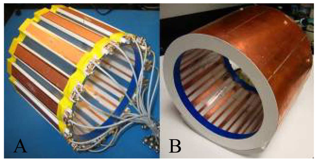
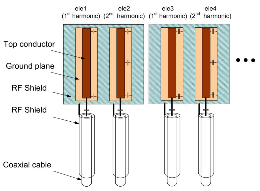
To demonstrate its performance, this RF shielding technique was applied to a proposed hybrid harmonic microstrip head array with first and second harmonic resonators interleaved-placed along the circumference of a cylinder [20]. Unlike the conventional microstrip array in which the coil elements are all the primary harmonic resonators, this design is composed of alternatively placed coil elements with the primary and second harmonics. Due to the different field distribution and the intrinsic decoupling between the primary and second harmonic elements, this design holds several advantages such as lower mutual coupling and improved parallel imaging performance along the sagittal/coronal plane. Fig. 3(a) shows a 16-channel transceiver microstrip array, which consists of eight primary harmonic elements and eight second harmonic elements for 1H imaging of human head at 7 T. The coil elements were built on Teflon strips that were 20 cm long, 3 cm wide, and 7 mm thick. The strip conductors and ground planes of the microstrip coil were made of 36-µm-thick adhesive-backed copper tape (3M, St. Paul, MN). The width of strip conductors was 0.63 cm, and the width of ground conductor was 2.54 cm. We connected two capacitors (Voltronics, Denville, NJ) at each coil elements for tuning and matching. For better adjustment, all tuning/matching circuits were arranged at one side of the strips. To compensate for the insufficient size of the ground plane of each microstrip element in the head transceiver array, a cylindrical slotted RF shielding with a diameter of 26.7 cm was added to the coil array as shown in Fig. 3(b). The cylindrical shielding had no physical connection with the coil array elements. The distance between the RF shielding and the ground plane of the coil elements was ~1.3 cm. This RF shielding was cut into eight pieces; within each piece there was one primary and one second harmonic element as schematically indicated in Fig. 4 to avoid possible eddy currents during imaging experiments. To minimize the RF interference between the resonant elements and feeding cables, the coaxial cable of each resonant element was shielded by a 10-cm-long copper tape which was directly connected to the coil shielding. The S-parameters, Q-factors before and after using the shields were measured with the network analyzer.
Fig. 3.
The 16-channel microstrip head array (a) without RF shield and (b) with RF shield.
Fig. 4.
Schematic of hybrid harmonic microstrip array with slotted RF shielding.
C. MRI Experiments
Based on the study results on the different shielding configurations listed in Table I, shielding scheme E that provides the best stability and quality factor seems an appropriate choice for the head transceiver arrays at 7T. MR imaging experiments using the proposed head array with RF shielding (scheme E) were performed on a whole body 7T/90 cm MR scanner (GE Healthcare, Milwaukee, WI). The scanner was equipped with two quadrature transmit channels and two T/R switches. To test the transceiver head arrays on this system, scans were conducted by connecting two coil elements (which are 90° apart) to the transmit channels each time simultaneously, and then combining all subimages offline. To avoid the signal cancellation due to the phase difference of the channels, the two coil elements scanned at each time were fed by RF power with 90° phase difference. During the experiment, all other coil elements were terminated with 50 Ω terminators.
Phantom images were acquired using the head arrays with and without the use of the additional RF shields for comparison. A 7T spherical water phantom with a 17-cm diameter (GE Healthcare, Milwaukee, WI) was used for imaging. To avoid potential RF-amplifier damage caused by the impedance mismatching of coil elements, the scan was manually performed and the feeding power of each coil element was controlled below 40 W both for shielded and unshielded cases. Each coil element was tuned to 298.1 MHz, the proton Larmor frequency of the 7 T scanner, and was matched to system 50 Ω with the presence of the phantom (better than −25 dB). Due to the environment-sensitive performance of the unshielded microstrip array, much effort and time was taken to fine tune the coil elements in the unshielded microstrip array. Axial plane images passing through the central of the phantom were acquired by using a gradient recalled echo (GRE) sequence with TR/TE = 150 ms/6.8 ms at 20° flip angle. Other MRI parameters were 256 × 256 matrix size, 18 cm × 18 cm field-of-view, NEX = 1. SNR measurements were taken from pairs of 32 × 32 pixels in each of the five positions at the center and periphery of images. Standard deviation of 10 × 10 pixels in the background was treated as noise for SNR calculation. Sagittal images from healthy volunteers were then acquired with the shielded transceiver array by using gradient recalled echo (GRE) sequence with TR/TE = 100 ms/6.9 ms at 20° flip angle. Other MRI parameters were 256 × 256 matrix size, 24 cm × 24 cm field of view, NEX = 4. Accelerated images with reduction factor (R) from 2 to 16 were calculated and reconstructed. Datasets were reconstructed offline with a customized GRAPPA-based parallel reconstruction algorithm [21] developed in our laboratory using MatLab (MathWorks, Natick, MA). Auto-calibration signal (ACS) lines that we used in this work were 10 for R = 2 ~ 5, 20 for R = 6 ~ 12, 40 for R = 13 ~ 16.
III. RESULTS
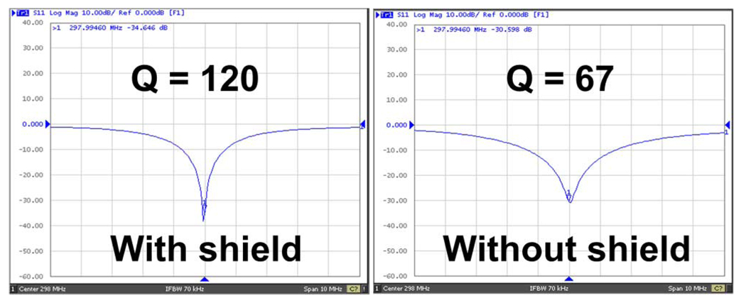
Q-factors of the shielded and unshielded microstrip volume arrays measured 120 and 67, respectively, yielding a doubled Q-factor gain and significantly reduced losses for the proposed design. The S11 plots obtained from a network analyzer for shielded and unshielded microstrip coils are shown in Fig. 5. In the unshielded microstrip array, the coil elements suffered from lower Q-factors and “cable-resonance.” The coil resonance was sensitive to the routing of coil feeding cables. On-site tuning and matching of the unshielded array was challenging due to instability of element resonance resulting from the “cable resonance” effect.
Fig. 5.
S11 parameters of the primary harmonic coil element without and with RF shields.
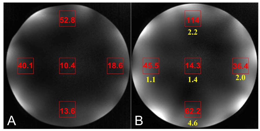
As revealed in Fig. 6, the SNR of the array with the RF shielding is improved over that without the RF shielding. For comparison, the shielded/unshielded SNR ratios are listed beneath the average SNR data of the shielded coil image [Fig. 6(b)]. Averaging the five experimental shielded/unshielded ratios, the RF shielded array yielded 2.3 times increase in the image SNR over that of the unshielded array. This experiment-based SNR gain was partially from the improved coil performance (e.g., loaded Q-factor), and partially from the uncontrollable mistuning and mismatching of the unshielded coil array.
Fig. 6.
Phantom images from (a) unshielded microstrip array and (b) shielded microstrip array. The SNR was measured from gradient echo images acquired using the same acquisition parameters and transmit power. Averaged, regional SNR measurements are shown on the images. Average shielded/unshielded SNR ratios are listed beneath the SNR data on the shielded image.
In the unshielded case, after loading the unshielded array with a human head and moving the coil array into 7 T magnet for scanning, the resonance peaks of the coil elements shifted by 0.2 MHz to 0.4 MHz. Impedance matching of the coil elements, which was originally −25 dB or better, had also degraded to the range between −15 dB and −25 dB. Moving the coil in and out the magnet in this case did not make significant change in its tuning and matching. However, due to the severe “cable resonance” resulted from the imperfect ground, the unshielded microstrip array was extremely sensitive to its surroundings, making the on-site tuning and matching difficult. In the proposed shielded microstrip array, RF interference between resonant elements and feeding cables, and also among feeding cables themselves were reduced, resulting in an improved stability of coil resonance and ultimately improved imaging performance. Compared with the unshielded microstrip array, the shielded microstrip array diminished the frequency shift before and after moving into the magnet. The resonance frequency shifts outside and inside the magnet were within 0.1 MHz. Impedance matching of each element was also better than −20 dB after moving the coil into the center of the magnet. It reduced the on-site tuning/matching effort. Isolations between adjacent elements were slightly degenerated after shielding (from −1 dB to −4 dB), but still retained a S21 of −15 dB or better when loaded with human head.
Fig. 7 shows the images acquired from a healthy volunteer using the shielded microstrip head transceiver array at 7 T. The image with reduction factor of 1 (R = 1) was combined by using the sum-of-squares method. Parallel imaging using GRAPPA with reduction factors 2–16 at different numbers of ACS lines were also reconstructed. Imaging with high acceleration rates demonstrated robust parallel imaging capabilities of the proposed shielded microstrip coil array for in vivo MR applications at 7 T. It is generally difficult to achieve high acceleration in parallel imaging, particularly when 1-D acceleration is used. The use of tailored algorithms and image processing methods would certainly help to further minimize the image artifacts and background noise, especially when the reduction factor applied is greater than 3.
Fig. 7.
Head images acquired with the shielded microstrip array at 7 T. When acceleration R is 1, the image was reconstructed by sum-of-squares method; the images with R = 2–6 were reconstructed offline by using GRAPPA. When R is 1–5, ACS lines for R = 1–5 is 10, for R = 6–12 is 20, for R = 13–16 is 40. Images were acquired with a GRE pulse sequence (Flip angle 20°, Matrix size 256 × 256, Slice Thickness 3 mm, TR/TE 100 ms/6.9 ms, and FOV 24 cm × 24 cm).
Note that specific absorption rate (SAR) is critical for high field human imaging studies, especially for 7 T imaging. The RF shielding in a microstrip head array with a large number of densely placed resonant elements may significantly increase the loaded Q-factors, indicating that the coil efficiency is improved and less transmit power is needed in comparison with the coil arrays without RF shielding.
IV. DISCUSSION AND CONCLUSION
An improved microstrip transceiver volume array for human head parallel imaging at the ultrahigh field of 7 T was designed and tested. The treatment of RF shielding on coil elements and feeding cables significantly improved the coil’s resonance stability and quality factors, thus leading to an improved image quality and parallel imaging performance at 7 T. The method proposed in this work is also applicable for designing other 7 T microstrip coil arrays, such as knee and spine arrays. The RF shielding is particularly useful in designing human transceiver arrays, especially those with a large number of densely placed resonance elements for high acceleration rates, in which the ground planes of the microstrip resonant elements are usually not large enough to become a “true” ground due to the space limitation. The effects of an imperfect ground of each microstrip resonant element in the transceiver arrays eventually result in reduced quality factors and instable coil resonance. The use of slotted RF shielding [22], [23] in this work can potentially reduce possible eddy currents in some high-field applications where strong and fast gradients are demanded. The resonance stability measurement method introduced in this work provides a quantitative way to the RF coil’s “cable resonance” evaluation.
ACKNOWLEDGMENT
The authors would like to thank J. Lu for manuscript editing and proofreading.
This work was supported in part by the National Institutes of Health under Grant EB004453 (XZ), Grant EB007588 (DV), and Grant UL1 RR024131-01 (XZ), in part by the ITL-Bio04-10148 (SN), and in part by the California Institute for Quantitative Biosciences (XZ).
Footnotes
Color versions of one or more of the figures in this paper are available online at http://ieeexplore.ieee.org.
Contributor Information
Bing Wu, Department of Radiology and Biomedical Imaging, University of California San Francisco (UCSF), San Francisco, CA 94158 USA..
Chunsheng Wang, Department of Radiology and Biomedical Imaging, University of California San Francisco (UCSF), San Francisco, CA 94158 USA..
Douglas A. C. Kelley, GE Healthcare, San Francisco, CA 94158 USA.
Duan Xu, Department of Radiology and Biomedical Imaging, University of California San Francisco (UCSF), San Francisco, CA 94158 USA..
Daniel B. Vigneron, Department of Radiology and Biomedical Imaging, University of California San Francisco, San Francisco, CA 94158 USA and also with University of California–San Francisco/University of California–Berkeley Joint Graduate Group in Bioengineering, San Francisco, CA 94158 USA.
Sarah J. Nelson, Department of Radiology and Biomedical Imaging, University of California San Francisco, San Francisco, CA 94158 USA and also with University of California–San Francisco/University of California–Berkeley Joint Graduate Group in Bioengineering, San Francisco, CA 94158 USA.
Xiaoliang Zhang, Department of Radiology and Biomedical Imaging, University of California San Francisco (UCSF), San Francisco, CA 94158 USA and also with University of California–San Francisco/University of California–Berkeley Joint Graduate Group in Bioengineering and California Institute for Quantitative Biosciences (QB3), San Francisco, CA, 94158 USA (xiaoliang.zhang@radiology.ucsf.edu)..
REFERENCES
- 1.Chen CN, Sank VJ, Cohen SM, Hoult DI. The field dependence of NMR imaging. I. Laboratory assessment of signal-to-noise ratio and power deposition. Magn. Reson. Med. 1986;vol. 3(no. 5):722–729. doi: 10.1002/mrm.1910030508. [DOI] [PubMed] [Google Scholar]
- 2.Robitaille PM, Abduljalil AM, Kangarlu A, Zhang X, Yu Y, Burgess R, Bair S, Noa P, Yang L, Zhu H, Palmer B, Jiang Z, Chakeres DM, Spigos D. Human magnetic resonance imaging at 8 T. NMR Biomed. 1998;vol. 11(no. 6):263–265. doi: 10.1002/(sici)1099-1492(199810)11:6<263::aid-nbm549>3.0.co;2-0. [DOI] [PubMed] [Google Scholar]
- 3.Ugurbil K, et al. Imaging at high magnetic fields: Initial experiences at 4 T. Magn. Reson. Q. 1993;vol. 9(no. 4):259–277. [PubMed] [Google Scholar]
- 4.Ugurbil K, Hu X, Chen W, Zhu XH, Kim SG, Georgopoulos A. Functional mapping in the human brain using high magnetic fields. Philos. Trans. R. Soc. Lond. B Biol. Sci. 1999;vol. 354(no. 1387):1195–1213. doi: 10.1098/rstb.1999.0474. [DOI] [PMC free article] [PubMed] [Google Scholar]
- 5.Vaughan JT, Garwood M, Collins CM, Liu W, DelaBarre L, Adriany G, Andersen P, Merkle H, Goebel R, Smith MB, Ugurbil K. 7T vs. 4T: RF power, homogeneity, and signal-to-noise comparison in head images. Magn. Reson. Med. 2001;vol. 46(no. 1):24–30. doi: 10.1002/mrm.1156. [DOI] [PubMed] [Google Scholar]
- 6.Yacoub E, Shmuel A, Pfeuffer J, Van De Moortele PF, Adriany G, Andersen P, Vaughan JT, Merkle H, Ugurbil K, Hu X. Imaging brain function in humans at 7 Tesla. Magn. Reson. Med. 2001;vol. 45(no. 4):588–594. doi: 10.1002/mrm.1080. [DOI] [PubMed] [Google Scholar]
- 7.Lupo JM, Banerjee S, Kelley D, Xu D, Vigneron DB, Majumdar S, Nelson SJ. Partially-parallel, susceptibility-weighted MR imaging of brain vasculature at 7 Tesla using sensitivity encoding and an autocalibrating parallel technique; Proc. Conf. IEEE Eng. Med. Biol. Soc; 2006. pp. 747–750. [DOI] [PubMed] [Google Scholar]
- 8.Sodickson DK, Manning WJ. Simultaneous acquisition of spatial harmonics (SMASH): Fast imaging with radiofrequency coil arrays. Magn. Reson. Med. 1997;vol. 38(no. 4):591–603. doi: 10.1002/mrm.1910380414. [DOI] [PubMed] [Google Scholar]
- 9.Pruessmann KP, Weiger M, Scheidegger MB, Boesiger P. SENSE: Sensitivity encoding for fast MRI. Magn. Reson. Med. 1999;vol. 42(no. 5):952–962. [PubMed] [Google Scholar]
- 10.Ledden PJ, Duyn JH. Ultra-high frequency array performance: predicted effects of dielectric resonance; Proc. 10th Annu. Meeting ISMRM; p. 324. [Google Scholar]
- 11.Wiesinger F, Van de Moortele PF, Adriany G, De Zanche N, Ugurbil K, Pruessmann KP. Parallel imaging performance as a function of field strength-an experimental investigation using electrodynamic scaling. Magn. Reson. Med. 2004 Nov.vol. 52(no. 5):953–964. doi: 10.1002/mrm.20281. [DOI] [PubMed] [Google Scholar]
- 12.Adriany G, Van de Moortele PF, Wiesinger F, Moeller S, Strupp JP, Andersen P, Snyder C, Zhang X, Chen W, Pruessmann KP, Boesiger P, Vaughan T, Ugurbil K. Transmit and receive transmission line arrays for 7 Tesla parallel imaging. Magn. Reson. Med. 2005 Feb.vol. 53(no. 2):434–445. doi: 10.1002/mrm.20321. [DOI] [PubMed] [Google Scholar]
- 13.Zhang X, Ugurbil K, Chen W. Microstrip RF surface coil design for extremely high-field MRI and spectroscopy. Magn. Reson. Med. 2001;vol. 46(no. 3):443–450. doi: 10.1002/mrm.1212. [DOI] [PubMed] [Google Scholar]
- 14.Lee RF, Westgate CR, Weiss RG, Newman DC, Bottomley PA. Planar strip array (PSA) for MRI. Magn. Reson. Med. 2001;vol. 45(no. 4):673–683. doi: 10.1002/mrm.1090. [DOI] [PMC free article] [PubMed] [Google Scholar]
- 15.Zhang X, Ugurbil K, Chen W. Method and apparatus for magnetic resonance imaging and spectroscopy using microstrip transmission line coils. 7023209. U.S. Patent. 2006
- 16.Wu B, Zhang X, Qu P, Shen GX. Design of an inductively decoupled microstrip array at 9.4T. J. Magn. Reson. 2006 Jul. doi: 10.1016/j.jmr.2006.04.013. [DOI] [PubMed] [Google Scholar]
- 17.Wu B, Zhang X, Qu P, Shen GX. Capacitively decoupled tunable loop microstrip (TLM) array at 7 T. Magn. Reson. Imag. 2007 Apr.vol. 25(no. 3):418–424. doi: 10.1016/j.mri.2006.09.031. [DOI] [PubMed] [Google Scholar]
- 18.Zhang Z, Yip CY, Grissom W, Noll DC, Boada FE, Stenger VA. Reduction of transmitter B1 inhomogeneity with transmit SENSE slice-select pulses. Magn. Reson. Med. 2007 May;vol. 57(no. 5):842–847. doi: 10.1002/mrm.21221. [DOI] [PMC free article] [PubMed] [Google Scholar]
- 19.Brunner DO, Zanche N, Froehlich J, Baumann D, Pruessmann KP. A symmetrically fed microstrip coil array for 7T; Proc. 15th Annu. Meeting ISMRM; p. 448. [Google Scholar]
- 20.Wu B, Wang C, Xie Z, Zhang X. 16-channel microstrip array using 1st and 2nd harmonics for parallel imaging at 7T; Proc. 16th Annu. Meeting ISMRM; p. 437. [Google Scholar]
- 21.Qu P, Shen GX, Wang C, Wu B, Yuan J. Tailored utilization of acquired k-space points for GRAPPA reconstruction. J. Magn. Reson. 2005 May;vol. 174(no. 1):60–67. doi: 10.1016/j.jmr.2005.01.015. [DOI] [PubMed] [Google Scholar]
- 22.Shen GX. Double-sided stripline RF shield; Proc. 11th Annu. Meeting ISMRM; p. 4048. [Google Scholar]
- 23.Vaughan JT, Adriany G, Garwood M, Yacoub E, Duong T, DelaBarre L, Andersen P, Ugurbil K. Detunable transverse electromagnetic (TEM) volume coil for high-field NMR. Magn. Reson. Med. 2002 May;vol. 47(no. 5):990–1000. doi: 10.1002/mrm.10141. [DOI] [PubMed] [Google Scholar]


