Abstract
This paper presents a droplet-based microfluidic device for concurrent droplet charging and sorting by electrostatic actuation. Water-in-oil droplets can be charged on generation by synchronized electrostatic actuation. Then, simultaneously, the precharged droplets can be electrostatically steered into any designated laminar streamline, thus they can be sorted into one of multiple sorting channels one by one in a controlled fashion. In this paper, we studied the size dependence of the water droplets under various relative flow rates of water and oil. We demonstrated the concurrent charging and sorting of up to 600 droplets∕s by synchronized electrostatic actuation. Finally, we investigated optimized voltages for stable droplet charging and sorting. This is an essential enabling technology for fast, robust, and multiplexed sorting of microdroplets, and for the droplet-based microfluidic systems.
INTRODUCTION
Droplet-based microfluidics has emerged as a promising microfluidic platform for large-scale, ultralow-volume studies of biological and chemical experimentation.1, 2, 3, 4, 5, 6, 7 The compartmentalization of reagents or particles within droplets in an immiscible carrier fluid is an extremely effective way to prevent contamination and dilution effects and enhance reaction yields. Such droplets can encapsulate a variety of contents including genes, proteins, cells, viruses, worms, and particles.5, 6 The droplet-based microfluidic systems enable the generation, fusion, division, and even sorting of highly monodispersed nano- to picoliter droplets. Passive sorting of droplets can be initiated through the channel geometry8, 9 and pinched flow fractionation.10 Active ways to sort droplets are through the application of pneumatically controlled sheath flows,11 heating from a focused laser,12 surface acoustic wave,13 or electric forces.14, 15 The droplets can be either precharged on generation and driven by electrophoretic forces14 or neutral and driven by dielectrophoretic forces.15 The dielectrophoretic sorting method allowed droplet sorting rates up to 300 droplets∕s with a false positive error rate of 1 in 104 droplets or 2000 droplets∕s with a false positive error rate of 1 in 100 droplets.15 However, existing methods to sort microdroplets in the droplet-based microfluidics lie in a binary sorting; the droplets are simply to be sorted to keep and discard channels.12, 13, 14, 15
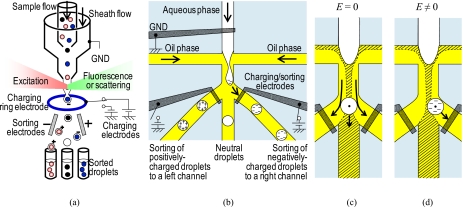
In this paper, we introduce a platform technology that has the potential for high-throughput multiplexed sorting of microdroplets into any designated sorting channel, rather than the binary sorting. The technology enables concurrent droplet charging and sorting by electrostatic induction on droplet formation and electrostatic steering of the precharged droplets into designated laminar streamlines. This paper demonstrates simple, effective, triple sorting of positively charged, negatively charged, and uncharged droplets without cell encapsulation. We present a module that generates, charges, and sorts individual droplets one by one in a controlled fashion, thus enabling precise and rapid sorting over the individual droplets, similar to conventional fluorescence activated cell sorting (FACS) systems [Fig. 1a].16, 17, 18, 19 Moreover, because all control is carried out by electrostatic actuation, there are no moving parts, and sorting rates as high as 600 droplets∕s are feasible. This is an essential enabling technology for fast, robust, and multiplexed sorting of microdroplets, and for the droplet-based microfluidic platform.
Figure 1.
(a) Schematic of conventional FACS systems. (b) Schematic of concurrent droplet charging and sorting by charging droplets electrostatically and steering the precharged droplets into designated streamlines. (c) Behavior of a droplet without the applied electric field. (d) Behavior of a droplet with the applied electric field to steer the droplet into a right sorting channel.
MATERIALS AND METHODS
Concept
Figure 1 shows a proposed concept of concurrent droplet charging and sorting by electrostatic actuation. Our proposed device consists of three electrodes for the electrostatic actuation. One electrode is placed under a water stream. The other two electrodes are placed under the entrances of each sorting channel, except a middle channel. While grounding the water stream, we apply positive or negative voltage pulses to one of the induction∕sorting electrodes. At this point, the grounded water stream carries no current and behaves as a conductor, whereas oil is an insulator, then electrostatic actuation charges the water-oil interface like a capacitor. While a water-in-oil droplet forms at the orifice of a flow focusing nozzle, the charge of the water-oil interface remains on the droplet. The mutual repulsion of like charges will cause a redistribution of charge in the conductive droplet, such that any excess charges are uniformly distributed on the surface of the conductor. Then, using the same voltage pulses between the grounded water stream and the induction∕sorting electrodes, we can steer the precharged droplet to one of the side sorting channels during or right after a droplet charging process.
Consider a precharged droplet that is formed at the orifice of the flow focusing nozzle to be sorted, as shown in Fig. 1b. The precharged droplet is driven by an electric force FE given by
| (1) |
where q is the precharge on the droplet and E is the applied electric field. The behavior of the droplet without and with the applied electric field is illustrated in Figs. 1c, 1d, respectively. With no applied electric field, the uncharged droplet will flow into a middle channel because the droplet is within the laminar flow region flowing into the middle channel. On the other hand, in order to sort a precharged droplet into the side channels, the droplet needs to flow within the laminar flow regions flowing into the side channels. When the electric field is applied to the precharged droplet, the droplet crosses over a borderline between two laminar flow regions, and it will flow into the side channels. Thus, triple sorting of positive, negative, or neutral droplets can be done by the electrostatic actuation. Unlike the FACS, it is not necessary to apply positive voltages to the left electrode and negative voltages to the right electrode separately. Since the same electrodes are used for both charging and sorting processes, the droplets can electrostatically be coated with either positive or negative charges. At the same time, the precharged droplets can be electrostatically steered into any designated laminar streamline where the droplets can flow into one of the triple sorting channels.
Device fabrication
We used soft lithography to pattern microfluidic channels in polydimethylsiloxane (PDMS). For a soft mold, negative photoresist (SU-8 2025) was spin coated on a silicon wafer with a thickness of 50 μm, and patterned using a conventional UV photolithography method. Microfluidic channels with a width and a height of 50 μm were molded. Cr∕Au (20 nm∕80 nm) electrodes were patterned on a slide glass substrate (25×76 mm2) using a standard photolithography technique. We designed those electrodes to be exposed in a microfluidic channel. The exposed electrode area over the microfluidic channel is 50×25 μm2 for both electrodes, and the distance between the charging∕sorting electrode and the nozzle is 200 μm. The glass substrate with the electrodes and the PDMS layer with the microfluidic channels were subsequently exposed to O2 plasma, aligned under a microscope, and sealed irreversibly. Then, we baked the device on a hotplate for 1 h at 70 °C to increase bonding strength between the glass substrate and the PDMS layer. Our device consisted of two inlets, one for the water stream and the other for the oil stream, and three outlets where the droplets could be sorted.
Device operation
De-ionized (DI) water was used as the aqueous phase, and hexadecane with a density of 0.77 g∕cm3 and dynamic viscosity of 8×10⁻³ Pa s was used as the oil phase. A nonionic surfactant (2% Tween-20) was added into the DI water to prevent droplet coalescence. Also, the use of the nonionic surfactant will minimize the possible electrokinetic effects that can be expected during the electrostatic actuation.20 These fluids were supplied from two different syringe pumps (KD scientific) to the device. The electrode, which was under the water stream, was connected to the ground, and the other two electrodes were connected to the positive or negative voltages. All the voltage pulses were supplied by a high-voltage sequencer (HVS448-1500, LabSmith, Livermore, CA). which was connected to a control computer. We generated a square function from a high-voltage sequencer during our experiments and voltage magnitude was from 0 to 160 V. Experimental results were captured by a Nikon stereo-type microscope.
RESULTS AND DISCUSSION
We studied size dependence of the water droplets under various relative flow rates of the water and the oil. Then, we demonstrated the concurrent charging and sorting by synchronized electrostatic actuation. Finally, we investigated optimized voltages for stable droplet charging and sorting.
Droplet generation without voltages
The two most common methods for generating droplets in microfluidic channels are through the use of T-junctions and flow focusing geometries. We used a flow focusing nozzle configuration. Although the size or shape of the flow focusing nozzles strongly influences the size of droplets, other parameters such as the viscosity of the immiscible phases, use of surfactants, and surface tension of the channel can also be used to control the size ranges of droplets.7 When such parameters are fixed, the size of the water droplets is controlled by the relative volumetric flow rates of the water and the oil. The viscous forces overcome surface tension to create uniform droplets at the orifice of the flow focusing nozzle.
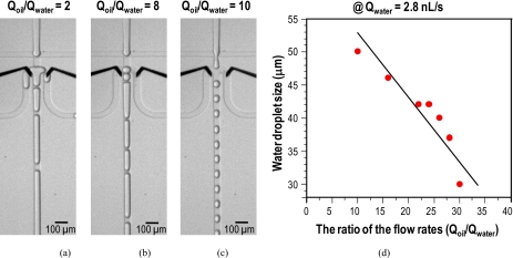
Figure 2 shows our proposed device with the flow focusing nozzle (which is connected to three sorting channels) and the experimental results regarding the relative volumetric flow rates. We measured the diameter of droplets when they passed out the nozzle. All droplets were assumed to be spherical because they were less than the nozzle dimension (50×50 μm2). The flow rate of the water (Qwater) was set to 2.8 nl∕s and the flow rate ratio (R=Qoil∕Qwater) increased from 2 to 30. The droplet generation was unstable at relatively low ratios (e.g., R≤8), as indicated in Figs. 2a, 2b. At low ratios, long pluglike droplets were formed and they were unstably divided into side sorting channels. With increasing flow ratio, the size of water droplets became smaller and they were stably formed within the flow focusing nozzle. With ratios larger than 10, as indicated in Fig. 2c, well-defined water droplets were formed. As shown in Fig. 2d, the size of the water droplets was controlled by the relative volumetric flow rates of the water and the oil. If shear stress is the only dominant mechanism for the water-in-oil droplet formation, the droplet size changes inversely to the flow rate: D∼1∕Qoil.7, 21 Thus, the larger the flow rate ratio, the smaller the droplet size. The decreasing trend of the droplet size to the flow ratio was observed in Fig. 2d, but the relationship was weak. It seems like that the droplet breakup mechanism depends on various parameters including the channel geometry, the wettability, the applied flow rates, and the fluid viscosities.7, 21 Furthermore, the droplet generation frequency (fd) increased with increasing flow ratio, which is determined by fd=Qd∕Vd, where Qd is the flow rate of the water phase and Vd is the droplet volume formed. For instance, with the ratio of 10, the droplet generation frequency was 43 droplets∕s (65 pl), and with the ratio of 30, it was 200 droplets∕s (14 pl).
Figure 2.
Experimental results on the relative volumetric flow rates and the droplet sizes without the applied voltages. Flow rate of the water was set to 2.8 nl∕s and the flow rate ratio (R=Qoil∕Qwater) was increased from 2 to 30. (a) Unstable droplet generation when R=2. (b) Unstable droplet generation when R=8. (c) Stable droplet generation when R=10. (d) Graph showing size dependence of the water droplets under various relative flow rates of the water and the oil.
Concurrent droplet charging and sorting
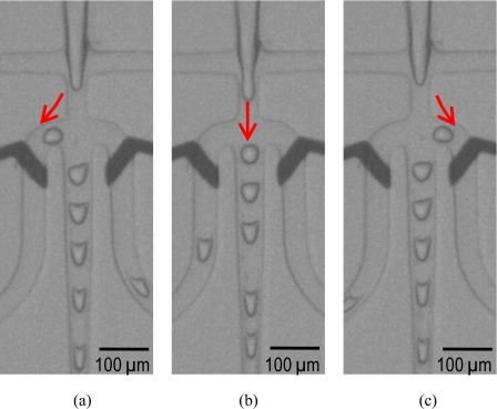
Figure 3 shows photographs of triple sorting of precharged droplets to a left sorting channel by actuating a left charging∕sorting electrode [Fig. 3a], uncharged droplets to a middle channel without electrostatic actuation [Fig. 3b], and precharged droplets to a right sorting channel by actuating a right charging∕sorting electrode [Fig. 3c]. In this demonstration, the flow rates of the water phase and the oil phase were 5 and 70 nl∕s, respectively. Without applied voltage, 200 droplets∕s (35 μm, 25 pl) were generated [Fig. 4a]. For the concurrent droplet charging and sorting, we applied dc pulses of 120 V (0.6 V∕μm) to the left and the right electrodes while grounding the water stream. The growing droplets were charged at the orifice of the flow focusing nozzle, and the precharged droplets were steered to the left or the right sorting channels depending on the applied electrostatic actuation.
Figure 3.
(a) Sorting of precharged droplets to a left sorting channel by actuating a left charging∕sorting electrode, (b) sorting of uncharged droplets to a middle channel without electrostatic actuation, and (c) sorting of precharged droplets to a right sorting channel by actuating a right charging∕sorting electrode. In this demonstration, 200 droplets∕s (35 μm, 25 pl) were generated with 5 nl∕s of the water stream and 70 nl∕s of the oil stream.
Figure 4.
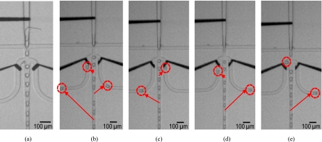
(a) Droplet generation (200 droplets∕s) without applied electrostatic actuation. Successful synchronized sorting with different sorting frequencies: single-droplet sorting per (b) three-droplet generation, (c) four-droplet generation, (d) five-droplet generation, and (e) six-droplet generation.
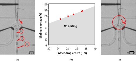
For complete sorting, the frequencies of the applied dc pulses and the droplet generation were matched. By synchronizing these frequencies, the concurrent sorting with droplet charging was successful with various sorting frequencies: single droplet sorting per three-droplet generation [Fig. 4b], four-droplet generation [Fig. 4c], five-droplet generation [Fig. 4d], and six-droplet generation [Fig. 4e]. Also we could sort a single droplet per two-droplet generation [Fig. 5a].
Figure 5.
Droplet charging and sorting with different actuation voltages. (a) One-droplet sorting per two-droplet generation with the minimum actuation voltage of 120 V, the droplet generation frequency of ∼200 droplets∕s. (b) Minimum actuation voltage Vmin to sort the droplets with respect to droplet size. For instance, a single droplet (25 μm, 8.3 pl) per two-droplet generation can be sorted up to the droplet generation frequency of 600 droplets∕s with a minimum actuation voltage of 88 V. (c) Unstable sorting with an applied voltage beyond a critical voltage of ∼160 V.
The growing droplet under an electric field E is driven by the competition between surface tension, viscous flow, and electric field. At high applied voltages where electric field-assisted flow is dominated, there is a significant additional force on the growing droplet, resulting in the decrease in droplet size with increasing applied field.14 By contrast, at low applied voltages where viscous flow is dominated, the droplet size dependence on the electric field is negligible. The crossover between viscous flow-dominated and electric field-dominated droplets can be estimated by the ratio (p) of the characteristic viscous stress (pV) to the characteristic electric stress (pE),22
| (2) |
where η is the viscosity, υ is the flow velocity, D is the droplet diameter, ε is the electrical permittivity of the oil, and E is the applied electric field. In our experiments, the estimated ratio was larger than 1 (p>1); for instance, p=2.1 for the 35 μm droplet with υ=30 mm∕s and E=0.6 V∕μm, and p=10.4 for the 25 μm droplet with υ=58 mm∕s and E=0.44 V∕μm, when μ=8×10⁻³ Pa s and ε=2.08×ε0. The order-of-magnitude analysis of the viscous and electric stresses shows that the applied electric field had a negligible effect on the size dependence. Therefore, the size of the water droplets was affected mainly by the relative flow rates of the water phase and the oil phase, rather than the applied voltages.
Voltage optimization
Figure 5 shows the concurrent droplet charging and sorting with different actuation voltages. Figure 5a shows a photograph of one-droplet sorting per two-droplet generation with the droplet generation frequency of ∼200 droplets∕s. A minimum actuation voltage of 120 V (0.6 V∕μm) was required for successful charging and sorting. The minimum voltage to sort droplets into the side channels was related with the size of the droplets. As water droplet generation frequency had to be synchronized to the switching frequency, we could indirectly verify the size of droplets and the water droplet generation frequency. This method was used for studying minimum and critical voltages for stable droplet charging and sorting. While the water flow rate was fixed to 5 nl∕s, the oil flow rate, the switching frequency, and the minimum actuation voltage were changed until it showed one by one sorting, then we fitted the water droplet size with the minimum actuation voltage. Figure 5b shows that the minimum actuation voltage Vmin to sort the droplets decreased with decreasing droplet size. Consider a precharged droplet is formed at the orifice of the flow focusing nozzle to be sorted. The precharged droplet will be driven by the competition between a drag force and an electric force. If the electric force is sufficient to overcome the drag force on the charged droplet, the droplet will cross over the borderline between two laminar flow regions. The Strokes drag force on a spherical particle is given by FD=6πaηυ, where a is the radius of the droplet, η is the viscosity of the oil, and υ is the velocity of the droplet. With a rough guess, a small droplet will experience a less drag force and it will be steered with a less actuation voltage Vmin. With large droplets, we need more actuation voltages to overcome the drag force. We could sort a single droplet (25 μm, 8.3 pl) per two-droplet generation up to the droplet generation frequency of 600 droplets∕s with a minimum actuation voltage of 88 V (0.44 V∕μm).
One of the critical concerns regarding electric fields is the question of cell viability if the cells are encapsulated in the droplets. However, this has not been an issue in the FACS systems due to the electrostatic induction of the droplets at the water-air interface and the electrostatic shielding of the precharged droplets. Likewise, in the electrostatic-based droplet charging and sorting device, cell damage will be negligible. As the grounded water stream carries no current, voltage drop occurs across the insulating oil between the water-oil interface and the charging∕sorting electrode rather than across the conductive water stream. It is also expected that the cells encapsulated in the precharged droplets will experience either less or zero electric field strengths because the electric field inside the conductor is zero (e.g., Gauss law).16 Therefore, it is expected that the cells can be sorted under the electrostatic actuation without damage.
On the other hand, if two electrodes are physically exposed to the water stream, the cells between the electrodes may experience high field strengths, and it may cause electroporation23 or electrical cell lyses.24, 25, 26 Figure 5c shows an image of unstable sorting with an applied voltage beyond a certain voltage Vcritical of ∼160 V (0.8 V∕μm). There is a significant additional electric force on the growing droplet if the electric-field strengths are too high. This resulted in the instability of the droplet formation at the flow focusing nozzle; a water streamline was generated rather than a water droplet.27 In turn, this formed an electrical short between the water streamline and the electrode. To prevent the instability due to electrical short, we can add an insulation layer over the electrode or place the electrode farther from the orifice. For the current design without the insulation layer, the operational voltage Vop needs to be Vmin<Vop<Vcritical to sort droplets one by one in a controlled fashion.
CONCLUSION
We presented a droplet-based microfluidic platform technology that can generate, charge, and steer individual water-in-oil droplets one by one in a controlled fashion. This was accomplished by electrostatic induction on the droplet formation and electrostatic steering of the precharged droplets into designated sorting channels. We showed triple sorting of positively charged, negatively charged, and uncharged droplets without cell encapsulation that has to be done for cell sorting applications. We demonstrated the concurrent charging and sorting of up to 600 droplets∕s by synchronized electrostatic actuation. The operational voltage needed to be larger than the minimum actuation voltage to overcome the transversal drag force on the charged droplet and smaller than the critical voltage for stable droplet charging and sorting. The proposed electrostatic-based droplet charging and sorting technology has the potential for simple, effective, multiplexed sorting of microdroplets.
ACKNOWLEDGMENTS
This work was supported by the NSF under ECCS∕EPDT program (Contract No. 0736501).
References
- Teh S. Y., Lin R., Hung L. H., and Lee A. P., Lab Chip 8, 198 (2008). 10.1039/b715524g [DOI] [PubMed] [Google Scholar]
- Kelly B. T., Baret J. C., Taly V., and Griffiths A. D., Chem. Commun. (Cambridge) 2007, 1773. 10.1039/b616252e [DOI] [PubMed] [Google Scholar]
- Taly V., Kelly B. T., and Griffiths A. D., ChemBioChem 8, 263 (2007). 10.1002/cbic.200600425 [DOI] [PubMed] [Google Scholar]
- Song H., Chen D. L., and Ismagilov R. F., Angew. Chem., Int. Ed. 45, 7336 (2006). 10.1002/anie.200601554 [DOI] [PMC free article] [PubMed] [Google Scholar]
- Huebner A., Sharma S., Srisa-Art M., Hollfelder F., Edel J. B., and Demello A. J., Lab Chip 8, 1244 (2008). 10.1039/b806405a [DOI] [PubMed] [Google Scholar]
- Joanicot M. and Ajdari A., Science 309, 887 (2005). 10.1126/science.1112615 [DOI] [PubMed] [Google Scholar]
- Cristini V. and Tan Y. C., Lab Chip 4, 257 (2004). 10.1039/b403226h [DOI] [PubMed] [Google Scholar]
- Tan Y. C., Fisher J. S., Lee A. I., Cristini V., and Lee A. P., Lab Chip 4, 292 (2004). 10.1039/b403280m [DOI] [PubMed] [Google Scholar]
- Tan Y. C., Ho Y. L., and Lee A. P., Microfluid. Nanofluid. 4, 343 (2008). 10.1007/s10404-007-0184-1 [DOI] [Google Scholar]
- Yang C. -H., Lin Y. -S., Huang K. -S., Huang Y. -C., Wang E. -C., Jhong J. -Y., and Kuo C. -Y., Lab Chip 9, 145 (2009). 10.1039/b807454b [DOI] [PubMed] [Google Scholar]
- Lee C. -Y., Lin Y. -H., and Lee G. -B., Microfluid. Nanofluid. 6, 599 (2009). 10.1007/s10404-008-0340-2 [DOI] [Google Scholar]
- Baroud C. N., de Saint Vincent M. R., and Delville J. P., Lab Chip 7, 1029 (2007). 10.1039/b702472j [DOI] [PubMed] [Google Scholar]
- Franke T., Abate A. R., Weitz D. A., and Wixforth A., Lab Chip 9, 2625 (2009). 10.1039/b906819h [DOI] [PubMed] [Google Scholar]
- Link D. R., Grasland-Mongrain E., Duri A., Sarrazin F., Cheng Z. D., Cristobal G., Marquez M., and Weitz D. A., Angew. Chem., Int. Ed. 45, 2556 (2006). 10.1002/anie.200503540 [DOI] [PubMed] [Google Scholar]
- Ahn K., Kerbage C., Hunt T. P., Westervelt R. M., Link D. R., and Weitz D. A., Appl. Phys. Lett. 88, 024104 (2006). 10.1063/1.2164911 [DOI] [Google Scholar]
- Shapiro H. M., Practical Flow Cytometry, 4th ed. (Wiley, New York, 2003). [Google Scholar]
- Durack G. and Robinson J. P., Emerging Tools for Single-Cell Analysis: Advances in Optical Measurement Technologies (Wiley, New York, 2000). [Google Scholar]
- Eisenstein M., Nature (London) 441, 1179 (2006). 10.1038/4411179a [DOI] [PubMed] [Google Scholar]
- Huh D., Gu W., Kamotani Y., Grotberg J. B., and Takayama S., Physiol. Meas. 26, R73 (2005). 10.1088/0967-3334/26/3/R02 [DOI] [PubMed] [Google Scholar]
- Raccurt O., Berthier J., Clementz P., Borella M., and Plissonnier M., J. Micromech. Microeng. 17, 2217 (2007). 10.1088/0960-1317/17/11/007 [DOI] [Google Scholar]
- Tan Y. C., Cristini V., and Lee A. P., Sens. Actuators B 114, 350 (2006). 10.1016/j.snb.2005.06.008 [DOI] [Google Scholar]
- Dubash N. and Mestel A. J., Phys. Fluids 19, 072101 (2007). 10.1063/1.2742702 [DOI] [Google Scholar]
- Zhan Y. H., Wang J., Bao N., and Lu C., Anal. Chem. 81, 2027 (2009). 10.1021/ac9001172 [DOI] [PubMed] [Google Scholar]
- Lee D. W. and Cho Y. H., Sens. Actuators B 124, 84 (2007). 10.1016/j.snb.2006.11.054 [DOI] [Google Scholar]
- Gao J., Yin X. F., and Fang Z. L., Lab Chip 4, 47 (2004). 10.1039/b310552k [DOI] [PubMed] [Google Scholar]
- Lee S. W. and Tai Y. C., Sens. Actuators, A 73, 74 (1999). 10.1016/S0924-4247(98)00257-X [DOI] [Google Scholar]
- Malloggi F., Vanapalli S. A., Gu H., van den Ende D., and Mugele F., J. Phys.: Condens. Matter 19, 462101 (2007). 10.1088/0953-8984/19/46/462101 [DOI] [Google Scholar]


