Abstract
Electrokinetic transport of cylindrical cells under dc electric fields in a straight microfluidic channel is experimentally and numerically investigated with emphasis on the dielectrophoretic (DEP) effect on their orientation variations. A two-dimensional multiphysics model, composed of the Navier–Stokes equations for the fluid flow and the Laplace equation for the electric potential defined in an arbitrary Lagrangian–Eulerian framework, is employed to capture the transient electrokinetic motion of cylindrical cells. The numerical predictions of the particle transport are in quantitative agreement with the obtained experimental results, suggesting that the DEP effect should be taken into account to study the electrokinetic transport of cylindrical particles even in a straight microchannel with uniform cross-sectional area. A comprehensive parametric study indicates that cylindrical particles would experience an oscillatory motion under low electric fields. However, they are aligned with their longest axis parallel to the imposed electric field under high electric fields due to the induced DEP effect.
INTRODUCTION
Electrokinetic phenomena offer an efficient way to manipulate particles using only electric fields without moving parts,1, 2 and have been extensively used in lab-on-a-chip devices for particle characterization, trapping, focusing, separation, sorting, and assembly.2, 3, 4, 5, 6 The success of these electrically controlled microfluidic devices for particle transport relies on a comprehensive understanding of fluid and particle behavior in these devices. However, most existing theoretical7, 8, 9, 10, 11 and experimental12, 13, 14, 15, 16, 17, 18, 19 studies on the electrokinetic transport in microfluidic devices have been performed exclusively on spherical particles. In fact, a large amount of particles used in microfluidic applications, such as biological entities1 and synthetic nanowires,20, 21 is nonspherical. However, comprehensive understandings of the electrokinetic transport of nonspherical particles are currently very limited.
To date a small number of numerical studies on the electrokinetic transport of cylindrical particles have been performed using quasistatic and transient models. Ye et al.,22 Hsu et al.,23, 24 and Liu et al.25, 26 studied the translation of a finite cylinder concentrically and eccentrically positioned along the axis of a tube using a quasistatic method. The effect of the particle’s orientation on its transport, however, was not examined. As the particle’s orientation has great impact on its adjacent electric and flow fields, it may significantly alter the particle motion. As a result, a transient simulation accounting for the particle’s translation and rotation is necessary to capture the essential physical process of the electrokinetic transport of cylindrical particles. Davison and Sharp27, 28 implemented a transient numerical model to predict the electrokinetic motion of a cylindrical particle through a tube and an L-shaped microchannel.29 It was predicted that a cylindrical particle could experience an oscillatory motion in a straight channel28 and an L-shaped channel could be used to control the orientation of cylindrical particles.29 However, the aforementioned numerical studies did not examine the dielectrophoretic (DEP) effect on the particle transport, and the numerical predictions have not been verified by experiments. The ignoring of the induced DEP motion can cause significant errors in the particle’s velocity, trajectory, and orientation, which has been demonstrated by recent numerical and experimental studies of polystyrene bead electrophoresis through a converging-diverging and an L-shaped microchannel.11, 15
Dielectrophoresis refers to a nonlinear electrokinetic phenomenon30 in which a force is exerted on a dielectric particle when it is subjected to a spatially nonuniform electric field. This kind of electrokinetic phenomenon has been widely used to manipulate spherical particles in microfluidics such as particle trapping,31, 32, 33, 34, 35 separation,16, 35, 36, 37, 38, 39, 40, 41 focusing,14, 18, 35 and cell discrimination.42, 43 Previous numerical and experimental studies demonstrate that the DEP effect should be taken into account to study the electrokinetic transport of spherical particles where nonuniform electric fields are present.11, 15 Recently, a DEP-induced alignment phenomenon of nanowires and carbon nanotubes44, 45, 46, 47, 48, 49 to external electric fields was experimentally observed, indicating a significant DEP effect on the motion of cylindrical particles subjected to external electric fields. Considering the DEP effect, Winter and Welland50 predicted that nonspherical particles are always aligned with their longest axis parallel to the electric field using a transient model, which did not consider the distortions of the electric and flow fields by the presence of the particle. This approximation can lead to deviations from the experimentally observed particle behaviors.14, 16, 18
In this study, we present an experimental and numerical investigation of a transient electrokinetic transport of cylindrical cells in a straight microchannel under direct current (dc) electric fields. Maxwell stress tensor (MST) method, regarded as the most rigorous method for DEP calculation,51 is used in the numerical study. Fluid flow field, electric field, and particle motion are solved in a coupled manner to predict the particle transport. Section 2 describes the experimental setup while Sec. 3 introduces the mathematical model composed of the Navier–Stokes equations for the flow field and the Laplace equation for electric field defined in an arbitrary Lagrangian–Eulerian (ALE) framework and its numerical implementation. The experimental and numerical results are discussed in Sec. 4 with emphasis on the dc DEP effect on the orientation variation in particles. Concluding remarks are given in Sec. 5.
EXPERIMENTAL SETUP
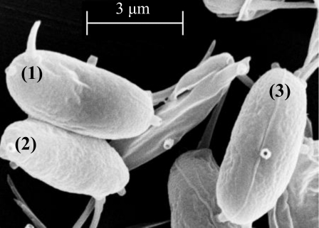
Desmodesmus cf. quadricauda (Fig. 1), a green alga of the chlorophyceae, was grown in RLH medium under fluorescent light (cool white plus, 6500 lx, continuous illumination) and aerated with high efficiency particulate air-filtered (HEPA) air. Algae were then fixed in 4% formaldehyde in 0.1 M phosphate buffer (pH=7.4) for 12 h at 4 °C, and rinsed three times in 0.1 M phosphate buffer prior to usage in the experiments. Formalin fixation of cells for scanning electron microscopy (SEM) was performed in 4% formaldehyde in 0.1 M sodium cacodylate buffer (pH=7.4) at 4 °C for 12 h. Cells for SEM were then postfixed with 2% osmium tetroxide in 0.1 M sodium cacodylate (pH=7.4) for 12 h at room temperature. Postfixed cells were filtered onto 3.0 μm polycarbonate filters (13 mm, Millipore, Billerica, MA) and dehydrated through graded ethanol (25%, 50%, 75%, 95%, and 100%). Dehydrated cells were critical point dried in a Polaron CPD7501 (Polaron, E. Sussex, England), sputter coated (E. Fullam, Latham, NY), and examined in a Leo 435VP scanning electron microscope.
Figure 1.
SEM micrograph of three Desmodesmus cf. quadricauda unicells.
A straight microchannel with a rectangular cross section was fabricated using a standard soft lithography technique52 with polydimethylsiloxane (PDMS), detailed procedure of which is given in a previous publication.15 The length, width, and depth of the microchannel are, respectively, 10 mm, 50(±1) μm, and 25(±1) μm. The diameter of the reservoirs located in the end of the microchannel is 6 mm. Pressure-driven flows were eliminated prior to each experiment by balancing the solution heights in the two reservoirs until cells inside the channel ceased movement. Two platinum electrodes connected to a dc power supply (Circuit Specialists Inc., Mesa, AZ) were placed in the two reservoirs to generate the electrokinetic particle transport in 1mM KCl solution, which was captured at a rate of 7.25 Hz via an inverted microscope imaging system (Nikon Eclipse TE2000U equipped with a Powerview™ charge coupled device camera, Lewisville, TX). The captured images were further processed using IMAGEJ (National Institutes of Health, http://rsbweb.nih.gov/ij/) to extract the location and orientation of the cells at each time step. The reading errors of a given cell’s location and angle were, respectively, ±0.645 μm (±2 pixels) and ±2°. The translational velocity was calculated by dividing the travel distance between adjacent cells over the time step in a series of successive images.
MATHEMATICAL MODEL AND NUMERICAL IMPLEMENTATION
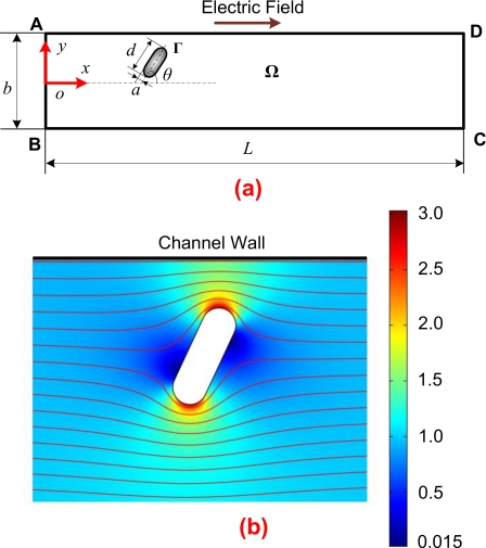
Davison and Sharp27 numerically investigated the electrophoretic motion of a sphere moving along a cylindrical capillary using two-dimensional (2D), axisymmetric, and three-dimensional (3D) geometries, and the difference between the results obtained from the 2D and 3D geometries is less than 4%. The proposed following mathematical model and its 2D numerical implementation have been successfully used to predict electrokinetic transport of spherical particles in various microchannels, indicating good agreements with the experimental results.11, 15 In addition, the experimental results of the electrokinetic transport of Desmodesmus cf. quadricauda cells and their corresponding 2D numerical simulations, presented in Sec. 4, are also in good agreement. Unlike pressure-driven flows, the electro-osmotic flow is a typical plug flow, 2D and 3D particles are expected to experience similar flow conditions. Although 3D simulations at the cost of dramatically increased computational time provide detailed information about the dynamics of the particle and the spatial and temporal distributions of the flow and electric fields, these remarkable agreements between experimental results and predictions of the 2D model suggest that a 2D model is sufficient to capture the essential physics of the electrokinetic particle transport in microfluidics. Furthermore, in all the experiments reported in this paper, cells are always well focused in the microscope and the entire length of the cell did not vary a lot during the particle transport, which suggests that the cell’s translation and rotation mainly happen on the plane of channel length and width [xy plane as shown in Fig. 2a]. Therefore, a 2D simulation of the mathematical model is adopted in the current study.
Figure 2.
(a) A 2D schematic view of a cylindrical particle in a straight microchannel. An external electric field is applied between the inlet AB and the outlet CD. (b) Distribution and streamlines of the electric field within the microchannel in the presence of a cylindrical particle. The color levels indicate the electric field intensity normalized by the electric field intensity in the absence of the particle, with the red color representing high electric field.
As illustrated in Fig. 1, Desmodesmus cf. quadricauda is very similar to a cylinder capped by two hemispheres adopted in the numerical simulation. Thus, we consider a cylindrical particle bearing a zeta potential of ζp electrokinetically moving in a straight microchannel filled with an incompressible and Newtonian fluid of density ρ and dynamic viscosity η, as shown in Fig. 2a. The 2D computational domain Ω is enclosed by the segments ABCD and the particle surface Γ. An electric field is applied between the inlet AB and the outlet CD to drive the particle transport. The channel walls BC and AD, bearing a uniform zeta potential of ζw, are considered to be rigid and nonconducting. The length and width of the channel are, respectively, L and b. The rigid and nonconducting particle with a length of d is capped by two hemispheres with radius a. A Cartesian coordinate system (x,y) with the origin at the center of the inlet is used in the present study. The initial location and angle between the longest axis of the particle and the centerline of the channel are (xp0,yp0) and θp0, respectively. The effects of Brownian motion can be ignored for the electrokinetic transport of micron-sized particles.29
The particle radius a, the zeta potential of the channel wall ζw, and the electrophoretic velocity of the particle U∞=(εfζw∕η)ζw∕a are used, respectively, as the characteristic length, characteristic electric potential, and characteristic velocity to normalize the governing equations. Therefore, the following normalizations are obtained, x=ax*, u=U∞u*, p=(ηU∞∕a)p*, ϕ=ζwϕ*, andt=(a∕U∞)t*, where the asterisk denotes dimensionless quantities.
Since the thickness of the electric double layer (EDL) adjacent to the charged surface is on the order of several nanometers, EDL is usually considered to be infinitesimal in microscale electrokinetics,2 which is true in the current study, since the EDL thickness is much smaller than the cell size and channel width. Hence, the net charge density in the computational domain Ω is zero according to the thin EDL approximation. The electric potential thus satisfies the Laplace equation
| (1) |
All rigid surfaces are considered to be electrically insulating,
| (2) |
The potential difference applied between the inlet and outlet is described by imposing
| (3) |
and
| (4) |
Under the thin EDL assumption, the fluid motion within the EDL is reduced to the Smoluchowski slip velocity on the charged surface.7 As the Reynolds number of the electrokinetic flow in the present study is less than 0.02, the fluid inertia is neglected. Therefore, the mass and momentum conservation of the fluid outside the EDL are then expressed by
| (5) |
and
| (6) |
where Re=ρaU∞∕η. Note that the transient term in Eq. 6 cannot be dropped because the system is physically time dependent. The change in the particle’s position and orientation will affect the local electric and flow fields, and thus the hydrodynamic and DEP forces and their corresponding torques acting on the particle. The existence of a torque on the cylindrical particle is a violation of the steady-state or quasistatic approximation.27
The fluid velocity adjacent to the channel wall is the slip velocity defined as the electro-osmotic flow within the EDL given by
| (7) |
Above, the quantity (I−nn)⋅∇*ϕ* denotes the electric field tangent to the charged surface, where I and n are the identity tensor and the unit normal vector pointing from the channel wall to the fluid domain, respectively.
Fluid velocity associated with the particle motion is incorporated with the Smoluchowski slip velocity to address the fluid boundary on the particle surface
| (8) |
where and represent the translational and rotational velocities of the particle, respectively. and represent the position vector of the particle surface and the particle center, respectively. γ=ζp∕ζw is the ratio of the zeta potential of the particle to that of the channel wall.
The total force exerted on the particle consists of the hydrodynamic force , originated from the flow field around the particle, and the electrokinetic force , which are obtained, respectively, by integrating the hydrodynamic stress tensor and the MST over the particle surface Γ* (Refs. 51, 53, 54) given by
| (9) |
and
| (10) |
Here E* is the electric field related to the electric potential by E*=−∇*ϕ*. The first term of the integrand on the right-hand side of Eq. 10 vanishes due to Eq. 2. Thus, Eq. 10 represents the pure DEP force exerted on the particle.
The translational and rotational velocities of the particle are governed by
| (11) |
and
| (12) |
where is the mass of the particle, is the moment of inertia of the particle, and T* is the torque exerted on the particle.
The center and the orientation of the particle are expressed by
| (13) |
and
| (14) |
where and represent the initial location and orientation of the particle, respectively. Above, the force, torque, mass, moment of inertia, and rotational velocity are normalized as F=ηU∞aF*, T=ηU∞a2T*, , , and . Note that the present mathematical model is not valid for the electrokinetic motion of nanoscale particles, in which the ionic mass transport, fluid flow, and electric fields within the EDL must be resolved.55, 56, 57, 58, 59, 60
The aforementioned equations are defined in an ALE framework, in which the fluid flow and the electric field are solved in a Eulerian framework and the particle motion is tracked in a Lagrangian fashion at the same time. The detailed implementation of the ALE algorithm applied in the simulation of particle transport is described in a previous study.11, 61 The particle-fluid-electric field coupled system is solved simultaneously using a commercial finite-element package COMSOL (version 3.5a, www.comsol.com) operating in a high-performance cluster. The computational domain Ω in Fig. 2a is discretized into quadratic triangular elements with a higher density around the particle and the channel wall. Numerical solutions presented in this study are fully converged with a relative error bound of 10−6 and more than 20 000 total elements (b*=22.22 and L*=225) with a minimum of 100 elements positioned adjacent to the particle surface through rigorous mesh-refinement tests.
RESULTS AND DISCUSSION
For comparisons with experimental observations parameters in numerical simulations performed in this section are chosen based on the fluid viscosity μ=1.0×10⁻³ kg∕(m s) and permittivity εf=7.08×10⁻¹⁰ F∕m. The translational velocity of a cylindrical particle parallel to the electric field moving along the axis of a tube under the thin EDL assumption is given as25
| (15) |
when the ratio of the tube radius to the particle radius is much higher than the ratio of the particle length to the particle radius. Above, Ez is the axial electric field in the absence of particles and λ is the ratio of the particle radius to the tube radius. Based on the experimentally obtained particle velocity Up, the zeta potential of PDMS, ζw=−80 mV,16, 62 and the given viscosity and permittivity of fluid, the averaged zeta potential of the Desmodesmus cf. quadricauda was estimated to be ζp=−42 mV. Due to the presence of the cylindrical particle, the electric field is nonuniform, especially around the particle, as shown in Fig. 2b. The following electric field intensities used to distinguish different electric fields are calculated by dividing the electric potential difference over the length of the channel.
Experimental results
Figures 3a, 3c, 3e illustrate the trajectories of Desmodesmus cf. quadricauda cells in a straight microchannel under electric fields of (a) 0.6, (c) 6, and (e) 12 kV∕m. These trajectories are obtained by superposing sequential images of a same cell into one single figure. Under a 0.6 kV∕m electric field, the orientation of the cell only has slight change as it translates. Under higher electric fields of 6 and 12 kV∕m, however, the longest axes of the cells become parallel to the electric field after a short travel distance from its initial location. The cell under 12 kV∕m moves slower than that under 6 kV∕m, which should be attributed to the variation in the cells’ zeta potentials. The detailed properties of the cells are listed in Table 1. Figures 3b, 3d, 3f represent the corresponding numerical predictions for cases in Figs. 3a, 3c, 3e, respectively, generated by the model proposed in Sec. 3. They are in good agreement with the experimental observations.
Figure 3.
Trajectories of cylindrical particles electrophoretically moving from left to right in a straight microchannel. The particle trajectories are obtained by superposing sequential images of the same particle into one single figure. The left gray images, (a), (c), and (e), are experimental observations under different electric fields, while the right images, (b), (d), and (f), are the corresponding numerical predictions. The time interval between adjacent particles in (a) and (b) is 0.7 s, while the time interval in other figures is 0.14 s.
Table 1.
Properties of cells in Fig. 3.
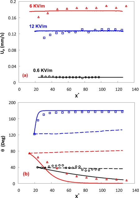
Figure 4a depicts a quantitative comparison between the predicted translational velocities of the cells and the experimental results under three different electric fields. The translational velocities predicted without considering the DEP effect are almost the same as those with DEP, thus, not shown here. Figure 4b indicates that the angle of the cell decreases very slowly under a 0.6 kV∕m electric field, which is similar to the numerical prediction without DEP. The numerical prediction with DEP appears to overpredict the angle decrease, which may be attributed to the slight shape mismatch between the real cell and the cylinder used in the simulation. Under a 6 kV∕m electric field, the cell becomes parallel to the electric field. The size difference in both ends of the cell, as shown in Fig. 3c, may cause the discrepancy between the experimental result and the numerical prediction with DEP. However, the angle of the cell predicted without DEP is not decreasing at all, resulting in a significant deviation from the experimental observation. Under a 12 kV∕m electric field, the cell becomes parallel to the electric field even faster than the case under a 6 kV∕m electric field. This phenomenon is also captured by the numerical prediction with DEP, however, significantly deviated from the numerical prediction without DEP. Therefore, the DEP effect must be taken into account for a precise prediction of the electrokinetic transport of cylindrical particles even in a uniform straight microchannel. From Eq. 10, the DEP force is proportional to the square of the electric field intensity. Under low electric fields, the DEP effect is too small to affect the rotation of the cell. Hence, the rotation of the cell is mainly dominated by electrophoresis and electro-osmosis. Once the DEP effect becomes larger, the alignment of the longest axis of a cylindrical particle parallel to the electric field becomes increasingly significant. This kind of phenomenon has been widely used to manipulate and assemble nanowires and carbon nanotubes onto electrodes.44, 45, 46, 47, 48, 49
Figure 4.
Comparison of (a) translational velocity and (b) angle between experimental results and numerical predictions. Circles, triangles, and squares are the experiments of Figs. 3a, 3c, 3e, respectively. Solid and dashed lines with the same color as the symbols are the corresponding numerical predictions with and without considering the DEP effect.
Effect of channel wall
According to the comparisons between the experiments and numerical simulations, the 2D numerical model is sufficient to capture the electrokinetic transport of cylindrical particles in a microchannel. All the following studies are conducted using the verified numerical model and described in a dimensionless manner. The dimensionless initial location of the particle is (10, 0). Except the section discussing the effect of particle’s initial angle, the initial angle is always 60°. The characteristic length is a=2.25 μm and the length of the entire channel is L*=225. The zeta potential of the channel is ζw=−80 mV.
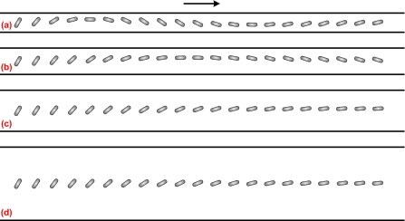
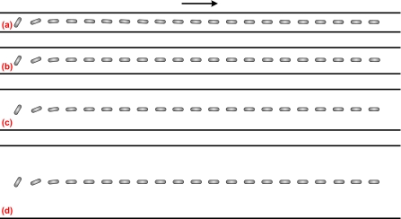
As the particle transport in microfluidic devices usually exists in confined microchannels, the wall effect on the particle transport is of great importance. Figure 5 depicts the trajectory of a cylindrical particle in a straight microchannel with different channel widths. The electric field intensity, aspect ratio of the particle, and the zeta potential ratio are E*=0.0169 (E=0.6 kV∕m), d∕a=6, and γ=0.525, respectively. When the channel width is b*=10, the cylindrical particle experiences an oscillatory motion, as shown in Fig. 5a. Because of the low electric field, the particle’s rotation is highly dominated by electrophoresis and electro-osmosis. As the aspect ratio of the particle is close to the channel width, the electric field between the particle and the channel is highly distorted, similar to Fig. 2b. The oscillatory motion is mainly induced by the fluctuation of the electric field due to the presence of the cylindrical particle. The predicted oscillatory motion is quite similar to the one predicted by Davison and Sharp28 without considering the DEP effect. However, the amplitude of the oscillatory motion reduces as the channel width increases, as shown in Figs. 5b, 5c, 5d. In addition, a longer travel distance of the particle is required to experience one cycle of oscillatory motion in a wider channel. For example, the travel distance of one-cycle oscillatory motion for b*=14 is roughly twice of that for b*=10. Therefore, the cylindrical particle with a nonzero initial angle experiences an oscillatory motion under low electric fields.
Figure 5.
Sequential images of rotation and translation of a cylindrical particle in a straight channel with different channel widths. The arrow denotes the translational direction of the particle. The simulation conditions are E*=0.0169, d∕a=6, and γ=0.525. (a) b*=10; (b) b*=14; (c) b*=22.22; (d) b*=40.
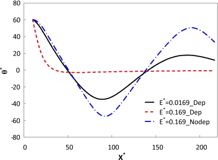
With the increase in the electric field, the oscillatory motion tends to disappear due to the domination of the DEP effect. Figure 6 illustrates the trajectory of a cylindrical particle in a straight microchannel under the same conditions as Fig. 5, except that the electric field is increased ten times (E*=0.169 and E=6 kV∕m). As the DEP effect becomes dominant, the particle becomes parallel to the electric field very quickly, and the wall effects on the particle orientation diminish. Figure 7 shows the orientation variations in a cylindrical particle along the centerline of the microchannel. The simulation conditions are d∕a=6, b*=10, and γ=0.525. The solid and dashed lines represent the cases in Figs. 5a, 6a, respectively. As discussed above, the particle experiences an oscillatory motion under low electric fields and becomes parallel to high electric fields. Even under low electric fields, the angle of the particle after 1 cycle of oscillation is lower than the initial value, which must be attributed to the DEP effect. If the DEP effect is ignored (denoted by the dashed-dotted line), the particle experiences an oscillatory motion even under a high electric field. In addition, its angle after 1 cycle of oscillation remains almost the same as its initial value. Thus, the DEP effect is of great importance in the electrokinetic transport of cylindrical particles under high electric fields.
Figure 6.
Sequential images of rotation and translation of a cylindrical particle in a straight channel with different channel widths. The arrow denotes the translational direction of the particle. The simulation conditions are E*=0.169, d∕a=6, and γ=0.525. (a) b*=10; (b) b*=14; (c) b*=22.22; (d) b*=40.
Figure 7.
Orientation variations in a cylindrical particle along the centerline of the microchannel. The simulation conditions are d∕a=6, b*=10, and γ=0.525.
Effect of electric field
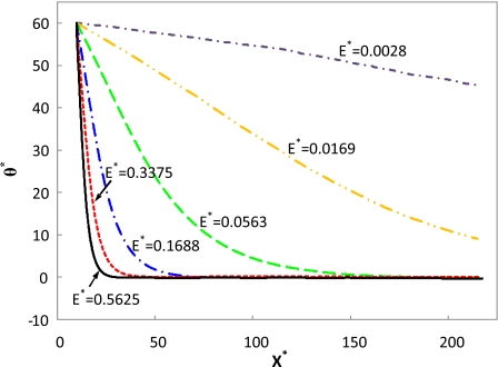
As stated earlier, the DEP effect is proportional to the square of the electric field intensity. Therefore, the electric field intensity should significantly influence the particle transport, including especially the rotation dynamics. Figure 8 depicts the effect of electric field intensity on the orientation variation in a cylindrical particle. The simulation conditions are d∕a=4, b*=22.22, and γ=0.525, which are very close to the experimental conditions used in the present study. Under a very low electric field, E*=0.0028 (E=0.1 kV∕m), the rotation mainly depends on electrophoresis and electro-osmosis. As the electric field increases, the DEP effect increases faster than electrophoresis and electro-osmosis effects. Under a medium electric field, E*=0.0169, the rotation is not only governed by electrophoresis and electro-osmosis but also a weak DEP effect. As the electric field increases further, the rotation mainly relies on the DEP effect. Even higher electric field intensities lead to faster alignments. Hence, high electric fields are to be used to achieve a fast alignment of nanowires and carbon nanotubes.
Figure 8.
Orientation variations in a cylindrical particle along the centerline of the microchannel under different electric fields. The simulation conditions are d∕a=4, b*=22.22, and γ=0.525.
Effect of zeta potential ratio
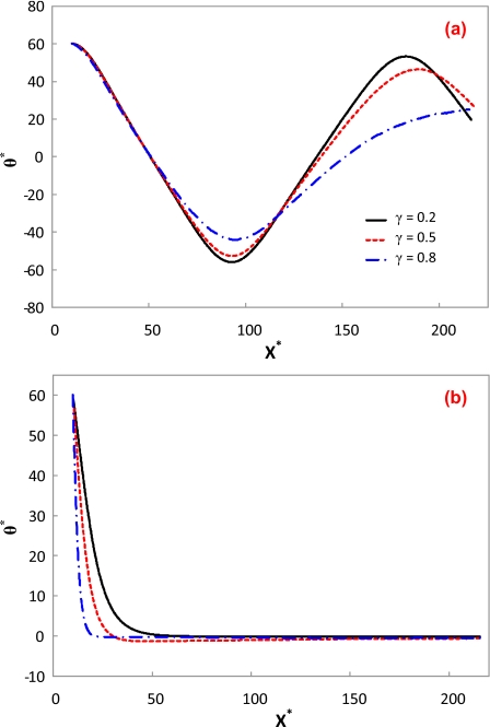
Figure 9 depicts the effect of zeta potential ratio on the orientation of the cylindrical particle under a low E*=0.0028 (Ε=0.1 kV∕m) and a high electric field E*=0.28 (Ε=10 kV∕m). Other simulation conditions are d∕a=6 and b*=10. Under the low electric field, the oscillatory motion of the particle varies with the zeta potential ratio, as shown in Fig. 9a. As the electrophoresis always retards the particle transport driven by the electro-osmotic flow in the present study, a lower zeta potential ratio leads to a higher electro-osmosis effect. Hence, the angle amplitude of the oscillatory motion increases and the period of the oscillatory motion shrinks as the zeta potential ratio decreases. Although the particles with different zeta potentials are all aligned under the high electric field, the alignment evolution still depends on the zeta potential ratio, as shown in Fig. 9b. As mentioned above, a lower zeta potential ratio leads to a higher particle mobility. Therefore, a longer travel distance of the particle is required to achieve the ultimate alignment.
Figure 9.
Orientation variations in a cylindrical particle with different zeta potential ratios along the centerline of the microchannel. The simulation conditions are d∕a=6, b*=10, and γ=0.525. The lines in (b) are in the same legend as (a). (a) E*=0.0028; (b) E*=0.28.
Effect of particle’s aspect ratio
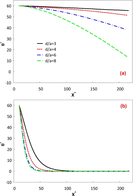
Figure 10 depicts the effect of the aspect ratio of the cylindrical particle on its transport under a low E*=0.0028 and a high electric field E*=0.28 with b*=22.22 and γ=0.2. Under the low electric field, the particle’s rotation is dominated by electrophoresis and electro-osmosis, while the DEP effect is negligible. Figure 10a indicates that a particle with a larger aspect ratio experiences a faster rotation. Apparently, a particle with a larger aspect ratio has a longer arm of force. In addition, it induces a more significant distortion of the electric field around it than a particle with a smaller aspect ratio. Thus, a particle with a larger aspect ratio usually experiences a larger torque. When the cylindrical particle degrades to a sphere (d∕a=2), the particle cannot rotate any more as it translates along the centerline of the channel.29 One can envision that a particle with a larger aspect ratio experiences the oscillatory motion more readily than that with a lower aspect ratio. Under the high electric field, a particle with a larger aspect ratio experiences a faster alignment than that with a lower aspect ratio, as shown in Fig. 10b. As the nanowires and carbon nanotubes usually have very large aspect ratios, they could have very fast alignment response to the electric field.
Figure 10.
Orientation variations in a cylindrical particle with different aspect ratios along the centerline of the microchannel. The simulation conditions are b*=22.22 and γ=0.2. The lines in (b) are in the same legend as (a). (a) E*=0.0028; (b) E*=0.28.
Effect of particle’s initial angle
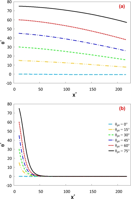
Figure 11 depicts the initial angle of the cylindrical particle on its transport under a low E*=0.0028 and a high electric field E*=0.28 with d∕a=6, b*=22.22, and γ=0.2. Under the low electric field, all the particles but the one with a zero initial angle experience a similar gradual angle reduction, as shown in Fig. 11a. As the channel width is much larger than the particle’s aspect ratio, the predicted angle decrease should be the beginning of an oscillatory motion. Davison and Sharp28 stated that a larger initial angle would cause a more significant oscillatory motion, which is correct under low electric fields. However, under the high electric field, all the particles with different initial angles rapidly align to the electric field, as shown in Fig. 11b. Hence, it is not always necessary to use an L-shaped channel, as proposed by Davison and Sharp,29 in order to achieve the alignment of cylindrical particles.
Figure 11.
Orientation variations in a cylindrical particle with different initial angles along the centerline of the microchannel. The simulation conditions are d∕a=6, b*=22.22, and γ=0.2. The lines in (a) are in the same legend as (b). (a) E*=0.0028; (b) E*=0.28.
CONCLUDING REMARKS
The effects of the dc DEP effect, arising from the nonuniform electric fields, on the electrokinetic transport of a cylindrical green algal cell in a straight microchannel are experimentally and numerically studied. The good agreement between the experiments and the numerical simulations verifies that the proposed theoretical model is reliable in predicting the electrokinetic transport of cylindrical particles. Furthermore, it is proved that the DEP effect must be taken into account for the prediction of the electrokinetic transport of cylindrical particles even in a uniform channel. Experimental results and numerical predictions indicate that cylindrical particles are always aligned with their longest axis parallel to the electric field under high electric fields, which is to be used to align and assemble nanowires44, 45, 46, 47, 48, 49 and biological tissues.63 In addition, a higher electric field leads to a faster particle alignment. Further numerical studies indicate that cylindrical particles can experience oscillatory motions under low electric fields. When the particle’s aspect ratio is very large and the channel is very narrow, it is very easy to observe the oscillatory motion within a short travel distance of the particle.
ACKNOWLEDGMENTS
The authors would like to acknowledge Dr. Andrew Gordon of Old Dominion University for culture of Desmodesmus cf. quadricauda used in the present study. This work is supported by the World Class University of the Ministry of Education, Science and Technology of Korea (Grant No. R32-2008-000-20082-0).
References
- Gomez F. A., Biological Applications of Microfluidics (Wiley Interscience, New Jersey, 2008). [Google Scholar]
- Li D., Electrokinetics in Microfluidics (Elsevier Academic, New York, 2004). [Google Scholar]
- Dittrich P. S. and Manz A., Nat. Rev. Drug Discovery 5, 210 (2006). 10.1038/nrd1985 [DOI] [PubMed] [Google Scholar]
- Hu G. Q. and Li D. Q., Chem. Eng. Sci. 62, 3443 (2007). 10.1016/j.ces.2006.11.058 [DOI] [Google Scholar]
- Weibel D. B. and Whitesides G. M., Curr. Opin. Chem. Biol. 10, 584 (2006). 10.1016/j.cbpa.2006.10.016 [DOI] [PubMed] [Google Scholar]
- Kang Y. J. and Li D. Q., Microfluid. Nanofluid. 6, 431 (2009). 10.1007/s10404-009-0408-7 [DOI] [Google Scholar]
- Keh H. J. and Anderson J. L., J. Fluid Mech. 153, 417 (1985). 10.1017/S002211208500132X [DOI] [Google Scholar]
- Ye C. Z. and Li D. Q., J. Colloid Interface Sci. 272, 480 (2004). 10.1016/j.jcis.2003.11.014 [DOI] [PubMed] [Google Scholar]
- Ye C. Z., Xuan X. C., and Li D. Q., Microfluid. Nanofluid. 1, 234 (2005). 10.1007/s10404-004-0016-5 [DOI] [Google Scholar]
- Unni H. N., Keh H. J., and Yang C., Electrophoresis 28, 658 (2007). 10.1002/elps.200600576 [DOI] [PubMed] [Google Scholar]
- Ai Y., Joo S. W., Jiang Y., Xuan X., and Qian S., Electrophoresis 30, 2499 (2009). 10.1002/elps.200800792 [DOI] [PubMed] [Google Scholar]
- Xuan X. C., Raghibizadeh R., and Li D., J. Colloid Interface Sci. 296, 743 (2006). 10.1016/j.jcis.2005.09.039 [DOI] [PubMed] [Google Scholar]
- Xuan X. C., Xu B., and Li D. Q., Anal. Chem. 77, 4323 (2005). 10.1021/ac048216x [DOI] [PubMed] [Google Scholar]
- Zhu J. and Xuan X., Electrophoresis 30, 2668 (2009). 10.1002/elps.200900017 [DOI] [PubMed] [Google Scholar]
- Ai Y., Park S., Zhu J., Xuan X., Beskok A., and Qian S., “DC electrokinetic particle transport in an L-shaped microchannel,” Langmuir (in press). [DOI] [PubMed]
- Kang K. H., Xuan X. C., Kang Y., and Li D., J. Appl. Phys. 99, 064702 (2006). 10.1063/1.2180430 [DOI] [Google Scholar]
- Kang Y. J., Li D. Q., Kalams S. A., and Eid J. E., Biomed. Microdevices 10, 243 (2008). 10.1007/s10544-007-9130-y [DOI] [PubMed] [Google Scholar]
- Zhu J., Tzeng T. -R., Hu G., and Xuan X., Microfluid. Nanofluid. 7, 751 (2009). 10.1007/s10404-009-0432-7 [DOI] [Google Scholar]
- Xuan X. C., Ye C. Z., and Li D. Q., J. Colloid Interface Sci. 289, 286 (2005). 10.1016/j.jcis.2005.03.045 [DOI] [PubMed] [Google Scholar]
- Appell D., Nature (London) 419, 553 (2002). 10.1038/419553a [DOI] [PubMed] [Google Scholar]
- Patolsky F., Zheng G. F., and Lieber C. M., Anal. Chem. 78, 4260 (2006). 10.1021/ac069419j [DOI] [PubMed] [Google Scholar]
- Ye C. Z., Sinton D., Erickson D., and Li D. Q., Langmuir 18, 9095 (2002). 10.1021/la026070w [DOI] [Google Scholar]
- Hsu J. P., Chen Z. S., Lee D. J., Tseng S., and Su A., Chem. Eng. Sci. 63, 4561 (2008). 10.1016/j.ces.2008.06.022 [DOI] [Google Scholar]
- Hsu J. P. and Kuo C. C., J. Phys. Chem. B 110, 17607 (2006). 10.1021/jp063313a [DOI] [PubMed] [Google Scholar]
- Liu H., Bau H. H., and Hu H. H., Langmuir 20, 2628 (2004). 10.1021/la035849i [DOI] [PubMed] [Google Scholar]
- Liu H., Qian S. Z., and Bau H. H., Biophys. J. 92, 1164 (2007). 10.1529/biophysj.106.089268 [DOI] [PMC free article] [PubMed] [Google Scholar]
- Davison S. M. and Sharp K. V., J. Colloid Interface Sci. 303, 288 (2006). 10.1016/j.jcis.2006.07.063 [DOI] [PubMed] [Google Scholar]
- Davison S. M. and Sharp K. V., Nanoscale Microscale Thermophys. Eng. 11, 71 (2007). 10.1080/15567260701337795 [DOI] [Google Scholar]
- Davison S. M. and Sharp K. V., Microfluid. Nanofluid. 4, 409 (2008). 10.1007/s10404-007-0192-1 [DOI] [Google Scholar]
- Gangwal S., Cayre O. J., Bazant M. Z., and Velev O. D., Phys. Rev. Lett. 100, 058302 (2008). 10.1103/PhysRevLett.100.058302 [DOI] [PubMed] [Google Scholar]
- Ying L. M., White S. S., Bruckbauer A., Meadows L., Korchev Y. E., and Klenerman D., Biophys. J. 86, 1018 (2004). 10.1016/S0006-3495(04)74177-6 [DOI] [PMC free article] [PubMed] [Google Scholar]
- Tuukkanen S., Kuzyk A., Toppari J. J., Hakkinen H., Hytonen V. P., Niskanen E., Rinkio M., and Torma P., Nanotechnology 18, 295204 (2007). 10.1088/0957-4484/18/29/295204 [DOI] [Google Scholar]
- Park S., Koklu M., and Beskok A., Anal. Chem. 81, 2303 (2009). 10.1021/ac802471g [DOI] [PubMed] [Google Scholar]
- Du J. -R., Juang Y. -J., Wu J. -T., and Wei H. -H., Biomicrofluidics 2, 044103 (2008). 10.1063/1.3037326 [DOI] [PMC free article] [PubMed] [Google Scholar]
- Cheng I. F., Chang H. -C., Hou D., and Chang H. -C., Biomicrofluidics 1, 021503 (2007). 10.1063/1.2723669 [DOI] [Google Scholar]
- Morgan H., Hughes M. P., and Green N. G., Biophys. J. 77, 516 (1999). 10.1016/S0006-3495(99)76908-0 [DOI] [PMC free article] [PubMed] [Google Scholar]
- Gascoyne P. R. C. and Vykoukal J., Electrophoresis 23, 1973 (2002). [DOI] [PMC free article] [PubMed] [Google Scholar]
- Çetin B., Kang Y., Wu Z. M., and Li D. Q., Electrophoresis 30, 766 (2009). 10.1002/elps.200800464 [DOI] [PubMed] [Google Scholar]
- Kang Y., Cetin B., Wu Z., and Li D., Electrochim. Acta 54, 1715 (2009). 10.1016/j.electacta.2008.09.062 [DOI] [Google Scholar]
- Lewpiriyawong N., Yang C., and Lam Y. C., Biomicrofluidics 2, 034105 (2008). 10.1063/1.2973661 [DOI] [PMC free article] [PubMed] [Google Scholar]
- Parikesit G. O. F., Markesteijn A. P., Piciu O. M., Bossche A., Westerweel J., Young I. T., and Garini Y., Biomicrofluidics 2, 024103 (2008). 10.1063/1.2930817 [DOI] [PMC free article] [PubMed] [Google Scholar]
- Gordon J. E., Gagnon Z., and Chang H. -C., Biomicrofluidics 1, 044102 (2007). 10.1063/1.2818767 [DOI] [PMC free article] [PubMed] [Google Scholar]
- Hwang H., Lee D. -H., Choi W., and Park J. -K., Biomicrofluidics 3, 014103 (2009). 10.1063/1.3086600 [DOI] [PMC free article] [PubMed] [Google Scholar]
- Evoy S., DiLello N., Deshpande V., Narayanan A., Liu H., Riegelman M., Martin B. R., Hailer B., Bradley J. C., Weiss W., Mayer T. S., Gogotsi Y., Bau H. H., Mallouk T. E., and Raman S., Microelectron. Eng. 75, 31 (2004). 10.1016/j.mee.2003.09.010 [DOI] [Google Scholar]
- Makaram P., Selvarasah S., Xiong X. G., Chen C. L., Busnaina A., Khanduja N., and Dokmeci M. R., Nanotechnology 18, 395204 (2007). 10.1088/0957-4484/18/39/395204 [DOI] [PubMed] [Google Scholar]
- Chang Y. K. and Hong F. C. N., Nanotechnology 20, 235202 (2009). 10.1088/0957-4484/20/23/235202 [DOI] [PubMed] [Google Scholar]
- Raychaudhuri S., Dayeh S. A., Wang D. L., and Yu E. T., Nano Lett. 9, 2260 (2009). 10.1021/nl900423g [DOI] [PubMed] [Google Scholar]
- Lao C. S., Liu J., Gao P. X., Zhang L. Y., Davidovic D., Tummala R., and Wang Z. L., Nano Lett. 6, 263 (2006). 10.1021/nl052239p [DOI] [PubMed] [Google Scholar]
- Monica A. H., Papadakis S. J., Osiander R., and Paranjape M., Nanotechnology 19, 085303 (2008). 10.1088/0957-4484/19/8/085303 [DOI] [PubMed] [Google Scholar]
- Winter W. T. and Welland M. E., J. Phys. D 42, 045501 (2009). 10.1088/0022-3727/42/4/045501 [DOI] [Google Scholar]
- Wang X. J., Wang X. B., and Gascoyne P. R. C., J. Electrost. 39, 277 (1997). 10.1016/S0304-3886(97)00126-5 [DOI] [Google Scholar]
- Duffy D. C., McDonald J. C., Schueller O. J. A., and Whitesides G. M., Anal. Chem. 70, 4974 (1998). 10.1021/ac980656z [DOI] [PubMed] [Google Scholar]
- Rivette N. J. and Baygents J. C., Chem. Eng. Sci. 51, 5205 (1996). 10.1016/S0009-2509(96)00337-5 [DOI] [Google Scholar]
- Yariv E., Phys. Fluids 18, 4 (2006). [Google Scholar]
- Schoch R. B., Han J. Y., and Renaud P., Rev. Mod. Phys. 80, 839 (2008). 10.1103/RevModPhys.80.839 [DOI] [Google Scholar]
- Chang H. -C. and Yossifon G., Biomicrofluidics 3, 012001 (2009). 10.1063/1.3056045 [DOI] [PMC free article] [PubMed] [Google Scholar]
- Qian S., Joo S. W., Hou W., and Zhao X., Langmuir 24, 5332 (2008). 10.1021/la703590p [DOI] [PubMed] [Google Scholar]
- Basuray S. and Chang H. C., Phys. Rev. E 75, 060501(R) (2007). 10.1103/PhysRevE.75.060501 [DOI] [PubMed] [Google Scholar]
- Qian S. and Joo S. W., Langmuir 24, 4778 (2008). 10.1021/la703924w [DOI] [PubMed] [Google Scholar]
- Zaltzman B. and Rubinstein I., J. Fluid Mech. 579, 173 (2007). 10.1017/S0022112007004880 [DOI] [Google Scholar]
- Ai Y., Joo S. W., Jiang Y., Xuan X., and Qian S., Biomicrofluidics 3, 022404 (2009). 10.1063/1.3122594 [DOI] [PMC free article] [PubMed] [Google Scholar]
- Venditti R., Xuan X. C., and Li D. Q., Microfluid. Nanofluid. 2, 493 (2006). 10.1007/s10404-006-0100-0 [DOI] [Google Scholar]
- Pethig R., Menachery A., Heart E., Sanger R. H., and Smith P. J. S., IET Nanobiotechnol. 2, 31 (2008). 10.1049/iet-nbt:20070027 [DOI] [PubMed] [Google Scholar]


